Planning and carrying out implant treatment in the edentulous maxilla is a more difficult and more extensive process than that involved in any other indication. It requires highly meticulous diagnostic investigations, which should routinely include conventional computed tomography (CT) or cone beam computed tomography (CBCT) with a custom template. This is a time-consuming but also very effective method, and should form part of standard diagnosis.
3D diagnosis with a custom template
Usually, the patient for edentulous implant treatment has already been fitted with a complete prosthesis. Provided the tooth set-up is correct, this prosthesis can be used as a basis for fabricating the implant template. To do this, it is duplicated in full and converted into a template made of a transparent but radiopaque plastic (Fig 6-1a). However, if the old restoration does not meet the expectations of either the patient or the dentist, the teeth will need to be set up again according to the principles of full mouth rehabilitation and also duplicated, to allow the optimal implant positions to be determined.
If the duplicated prosthesis is available as a basis for the template, concrete planning for implant placement can now begin. To begin with, it is advantageous to plan more implants than will actually be needed. If analysis of the CT scan images or the situation at the time of implant placement shows that the anatomical structure of the maxillary bone is not suitable for implants at all the planned locations, the described procedure leaves the option of selecting the most favorable sites.
In the first step, one hole is drilled in the template at each of the planned implant positions; these need to reproduce the longitudinal axes of the implants (Fig 6-1b). The drilled holes provide good reference points in both CT and CBCT imaging without producing artifacts.
To ensure that the template remains uncluttered, the author prefers to place the drill holes in positions 1, 3, 5, 6 and 7 (Fig 6-1c). The lateral incisors and the first premolars can then be positioned between the existing holes as required.
Before taking the radiograph, the template is stabilized in the patient’s mouth on the mandibular dentition, with an additional occlusion rim if necessary. A CT or CBCT scan is then performed on the patient while he or she bites down. The resultant data are fed into a planning program, eg, SimPlant (Dentsply) in Digital Imaging and Communications in Medicine (DICOM) format. In the SimPlant program, the maxilla can be visualized in three planes: axial, panoramic or cross-sectional, and also as a 3D reconstruction (Fig 6-1d). The panoramic and axial sections provide the best spatial orientation. However, the actual positioning of an implant usually takes place in the cross-sectional image. This section allows the position of the drill hole and the anatomy of the residual ridge to be brought into line (Fig 6-1e). In region 13, for example, a slight inclination palatally is sufficient to ensure that the implant is anchored in the bone (Fig 6-1f). In region 26, the drill hole corresponds almost exactly to the contours of the residual ridge (Fig 6-1g). However, shifting the implant slightly in the buccal direction allows it to be anchored more evenly in the bone that has been augmented following sinus elevation (Fig 6-1h).
The uniform distribution of thicker bone around the implant ensures a better supply of nutrients to the tissue. Due to anatomical reasons, however, no implants can be placed at some of the initially planned positions, such as region 21, so a substitute site needs to be found (Fig 6-1i). In addition to the template, the titanium pins used to attach the membrane (in this case, regions 13 and 16, buccal side in the axial section) during sinus elevation also provide good spatial reference points (Fig 6-1j).
Thanks to the accurate 3D diagnosis, it proved possible to place the 10 implants in the bone with good stability in the preoperatively planned positions (Fig 6-1k). At the patient’s request, the dental treatment required in the mandible was to take place at a later date.
For the treatment course, see pages 473–479.
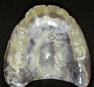
Fig 6-1a Radiographic template – prosthesis duplicated in clear plastic.
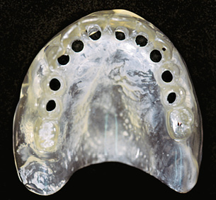
Fig 6-1b Drill holes at the planned implant positions.
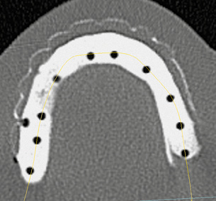
Fig 6-1c Template in the axial section of the CBCT scan.
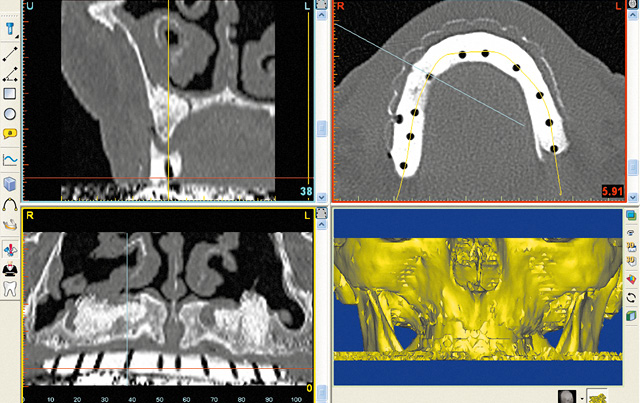
Fig 6-1d SimPlant planning with the template.
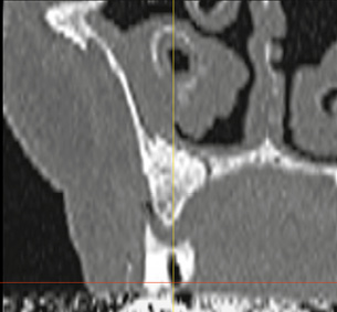
Fig 6-1e Cross section through the jaw in region 13.

Fig 6-1f Change in inclination of implant 13.
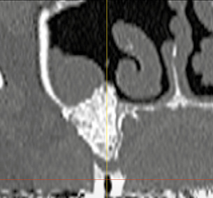
Fig 6-1g Drill hole for implant 26.
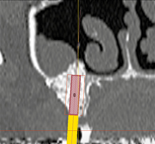
Fig 6-1h Implant 26 has been shifted slightly in the buccal direction.
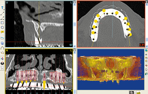
Fig 6-1i Unsuitable implant bed in region 21.
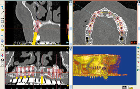
Fig 6-1j Planned positions for 10 implants. Titanium pins as spatial reference points.
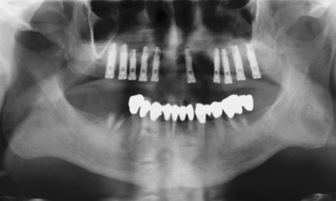
Fig 6-1k Panoramic radiograph after implant placement.
Note on the stabilization of the template
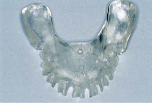
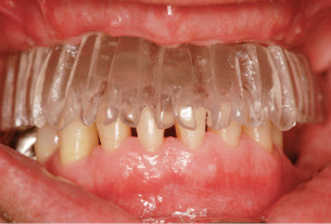
Fig 6-2b The template is stabilized by the mandibular dentition.
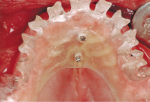
Fig 6-2c Stabilization screws driven into the palate.
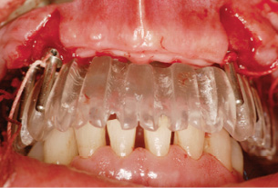
Fig 6-2d Additional stabilization with the direction indicators.
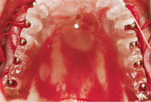
Fig 6-2e Checking the prepared implant beds.
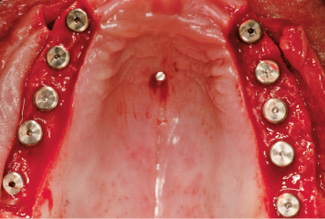
Fig 6-2f Implants inserted following removal of the template.
If an incision on the palatal side of the residual ridge is planned, the surgical template can be supported not only on the tuberosities, but also on the palate (Fig 6-2a). One or two additional perforations can be made in the plastic along the palatine suture, assuring stable placement of the template on screws driven into the palate (Fig 6-2a). As with the single-tooth template, the drill holes can be opened out on the labial/buccal side while preserving the tooth facets as much as possible (Fig 6-2b). If the incisal edges and occlusal surfaces of the teeth are reasonably intact, the template can be supported on the dentition of the opposing jaw, like a prosthesis (Fig 6-2b). The preserved facets also provide better spatial reference points for the surgeon.
If the position of the template has been defined with the mouth closed, its position should remain stable when the mouth is opened. The stabilization screws are driven into the palate through the perforations. The screws should be headless and with a smaller diameter than the perforations. They should be aligned parallel to each other and to the direction of insertion of the template (Fig 6-2c). These screws act as guidance pins, clearly defining the position of the template relative to the maxilla when it is inserted.
First, the template is used to drill holes for the canines and the first or second premolars. After this, the template can be stabilized further with the direction indicators, which prevent it from rotating (Fig 6-2d). With the template stable, the remaining bone beds are prepared and checked with more direction indicators (Fig 6-2e). Once the template is removed, the implants are inserted freehand into the prepared beds (Fig 6-2f). The stabilization screw is unscrewed from the palate.
Rehabilitation without reconstruction of the posterior maxilla
In an implant-supported restoration of the edentulous maxilla, the esthetic aspects involved in treating the anterior teeth combine with the functional aspects of restoring the posterior teeth. Above all, this means resolving the question of how the masticatory forces in the molar region (the center of occlusal force) are to be absorbed. One problem in the posterior maxilla is that very little bone tissue is often left after teeth are lost, and that this tissue also offers little retention for implants due to its cancellous structure. Without augmentation of the posterior maxilla (sinus floor elevation), implant placement is usually possible only in the anterior maxilla, where the bone supply tends to be sufficient. Even if full rehabilitation of the masticatory organ cannot be achieved, this form of restoration has also proved itself scientifically reliable. A hybrid prosthesis or a cantilever fixed implant bridge with a shortened dental arch (up to the first molar) can be incorporated.
Typical treatment course
Bar connector restoration on six implants
Baseline situation
This female patient with an edentulous maxilla was having problems with her complete denture, particularly with the fact that it covered the palate (Fig 6-3a). She wanted to have a securely fixed and palateless prosthesis.
Diagnostic tools
- Clinical examination
- Panoramic radiograph
- CBCT
- SimPlant planning
- Dental cast analysis
Treatment plan
1.Implant placement
2.Exposure and definitive prosthetic loading
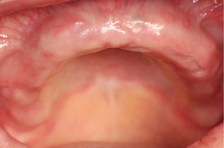
Fig 6-3a Edentulous maxilla.
Implant placement
Six implants were inserted into the anterior maxilla (Fig 6-3b). The two distal implants in regions 14 and 24 were inserted with a slight tilt in the mesial direction, to prevent contact with the maxillary sinus. This was followed by augmentation with the harvested bone chips and Bio-Oss (Geistlich). The augmentation material was covered with a membrane 30 × 40 mm in size, divided into two halves. The two halves of the membrane were attached at both the apical and coronal ends with titanium pins (Fig 6-3c).

Fig 6-3b Inserted implants with zones of labial/buccal dehiscence.
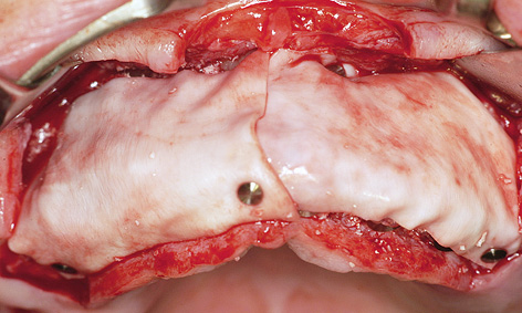
Fig 6-3c Augmentation.
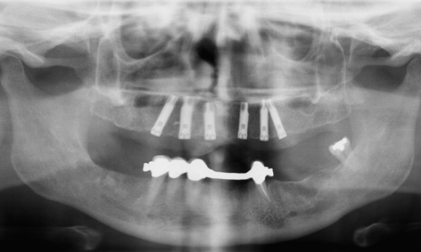
Fig 6-3d Postoperative panoramic radiograph.
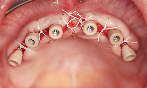
Fig 6-3e Exposure. Gingival deficit between the anterior implants.
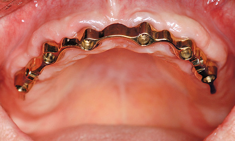
Fig 6-3f Milled non-noble alloy bar connector.
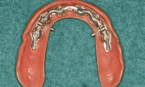
Fig 6-3g Metal framework of the prosthesis with incorporated MK1 attachments.
Exposure and prosthetic restoration
The implants were ready for exposure after 6 months (Fig 6-3d). The incision was made on the palatal side, to allow keratinized gingiva to be transposed toward the labial/buccal vestibule. Once the healing abutments were screwed on, the radius of the flap was increased to such an extent as to necessitate a deficit of approximately 5 mm at the midline (Fig 6-3e; see Note on page 427). At the time of incorporation of the prosthesis 2 months later, nothing identifiable remained of the soft tissue deficit created after the exposure (Fig 6-3f). The palateless prosthesis was stabilized on the bar connector that had been milled at the same time, and additionally “locked on” with two MK1 attachments (Figs 6-3g and 6-3h). When closed, the attachments were flush with the palate plate, so that they were virtually undetectable by the tongue (Fig 6-3i). From the labial/buccal side, the prosthesis can be designed like a complete denture and the access holes to the attachments are barely visible (Fig 6-3j). The follow-up radiograph after 4 years of functional use shows a stable bone situation around the implants (Fig 6-3k). The patient is happy not only about her securely fitting prosthesis and the absence of a plate covering her palate, but also that the cost involved was reasonable (Fig 6-3l).
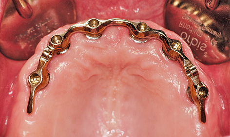
Fig 6-3h Parallel direction of insertion for the prosthesis.
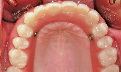
Fig 6-3i Palateless prosthesis after being locked into place.
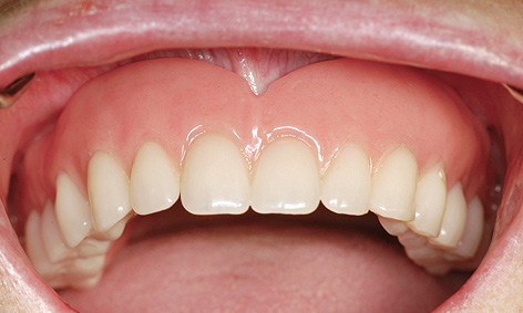
Fig 6-3j Barely visible access holes to the locking attachments.
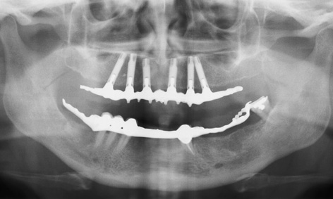
Fig 6-3k Panoramic radiograph taken after 4 years in functional use.

Fig 6-3l Patient following treatment completion.
Treatment course
- Implant placement and augmentation (2004)
- 6 months to exposure
- 2 months to final fabrication
Treatment
|
Surgery: |
Dr Christoph T. Sliwowski |
|
Prosthetics: |
Dr Gregor Cwajgart |
|
Dental technology: |
Gerhard Makowski |
Exposure technique
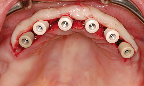
Fig 6-4a Distally extended palatal incision.
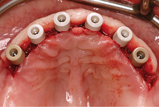
Fig 6-4b Gingival deficits distally of the implants.
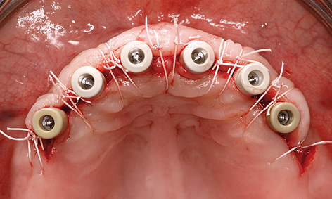
Fig 6-4c Suturing.
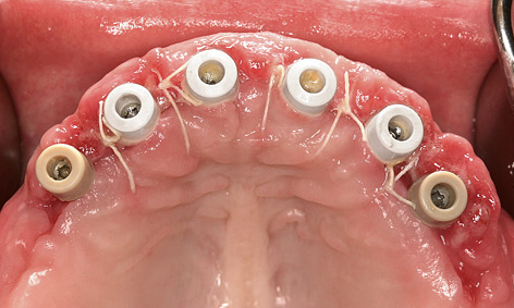
Fig 6-4d The distal gingival deficits have filled with granulation tissue.
When performing an implant exposure operation in the anterior region of the edentulous maxilla, the surgeon can use a technique that allows the keratinized gingiva to be transplanted in the labial/buccal direction. The incision is made continuously on the palatal side of the implants, but is extended by approximately 5 to 10 mm at the distal ends (Fig 6-4a). This increases the length of the flap in both directions and covers the distal implants on the buccal side (Fig 6-4b). The flap is secured with sutures in the interdental spaces and distally of the implants (Fig 6-4c). Within the next 2 weeks, the deficient regions distal from the implants normally fill completely with granulation tissue (Fig 6-4d)
Typical treatment course
Cantilever implant bridge on nine implants
Baseline situation
This female patient had an edentulous maxilla and wished to be fitted with a fixed restoration right from the start. Following the CT and panoramic radiograph analysis, the implant positions were established according to prosthetic aspects and taken into account in a custom-made template (Fig 6-5a).
Diagnostic tools
- Clinical examination
- Panoramic radiograph with template
- CT with template
- Dental cast analysis
Treatment plan
1.Implant placement
2.Exposure and long-term provisional restoration
3.Definitive prosthetic loading
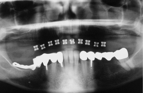
Fig 6-5a Panoramic radiograph with the template.
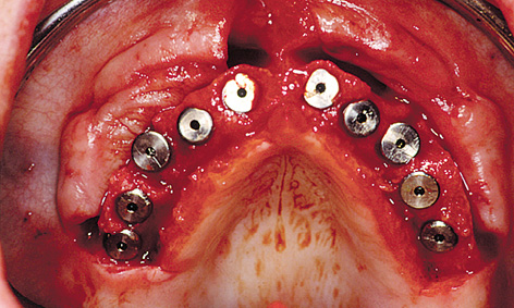
Fig 6-5b Implants in situ.
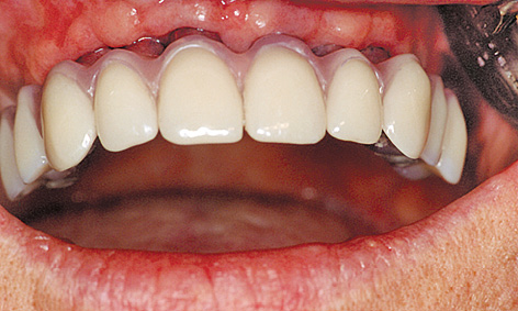
Fig 6-5c Long-term provisional restoration.
Implant placement and prosthetic restoration
It proved possible to insert all 10 implants at the planned positions (Fig 6-5b). At the time of exposure, however, it emerged that the 8.5-mm long implant at position 25 had not been osseointegrated. This meant that it had to be removed. A long-term provisional to be supported on the nine osseointegrated implants was fabricated according to the “Progressive Bone Loading” concept (see page 387; Fig 6-5c). This provisional was made of plastic with a metal framework and screwed onto EsthetiCone abutments (Nobel Biocare) (Fig 6-5d). The provisional could not be extended with cantilevers at the distal ends to avoid the risk of excess loading of the implants.
The definitive fixed restoration was fabricated after the patient had worn the fixed provisional for 1 year (Fig 6-5e). A cantilever could now be added to the definitive prosthesis (Fig 6-5f). After 5 years in situ, the front view of the denture is satisfactory, apart from the visible metal parts (Fig 6-5g). The panoramic radiograph shows a currently stable bone situation, along with the extent of the cantilevers (Fig 6-5h).
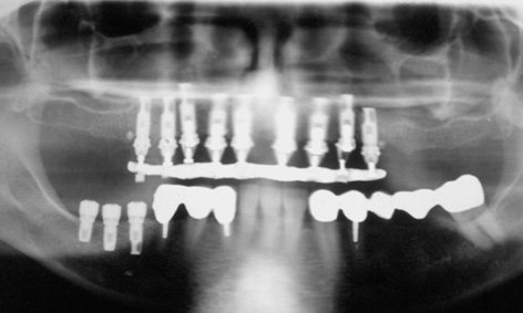
Fig 6-5d Postoperative panoramic radiograph.
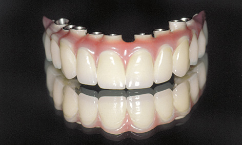
Fig 6-5e Definitive superstructure.
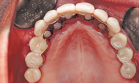
Fig 6-5f Superstructure with distal cantilever, incorporated after 1 year.
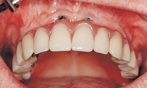
Fig 6-5g Clinical situation after 5 years.
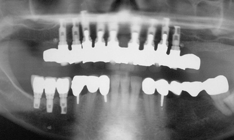
Fig 6-5h Stable bone situation.
Treatment course
- Implant placement (1997)
- 7 months to exposure and the long-term provisional
- 1 year to the definitive loading
Treatment
|
Surgery: |
Dr Christoph T. Sliwowski |
|
Prosthetics: |
Dr Michael Weber |
|
Dental technology: |
Horst Mosch |
Atypical treatment course – problematic baseline situation
Removable restoration – incidental finding by CT imaging
Baseline situation
For a number of years, this female patient had worn an overdenture as her maxillary restoration. However, the two canines that had supported the denture now needed to be extracted (Fig 6-6a). Therefore, the plan was to fit her with a removable bar connector prosthesis on six implants.
Diagnostic tools
- Clinical examination
- Panoramic radiograph with template
- CT with template
- Dental cast analysis
Treatment plan
1.Extraction of the impacted tooth and implant placement
2.Exposure, extraction and definitive prosthetic loading
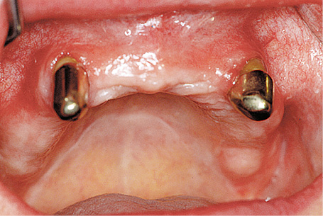
Fig 6-6a The non-preservable canines, which have held the overdenture in place.
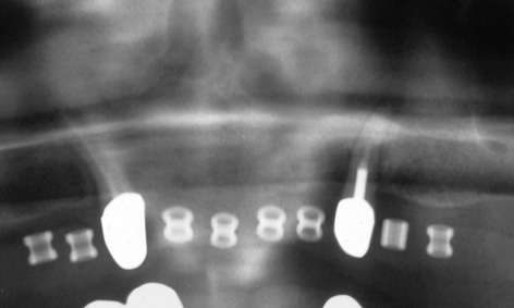
Fig 6-6b Panoramic radiograph with template. One retained tooth, barely visible.
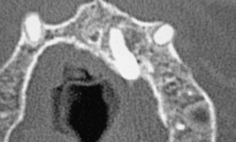
Fig 6-6c The retained tooth on the CT scan image.
Implant placement and extraction
However, the diagnostic investigations for the patient’s restoration revealed an incidental finding. On the panoramic radiograph (Fig 6-6b) one can barely distinguish an ectopic, impacted tooth in the maxillary bone in regions 21 to 23. The root apex of this tooth was close to the planned implant position (Fig 6-6c). The three-dimensional (3D) visualization in the CT scan allowed the position of this tooth to be accurately determined. The vertical sections show that the body of the tooth runs from the palate and into the nasal cavity (Fig 6-6d). During implant placement, the palatal mucosa was dissected away, the tooth divided and removed. The extracted tooth can be seen in Fig 6-6e. Following the extraction, the implants were successfully inserted into region 21 and five further positions, as planned.
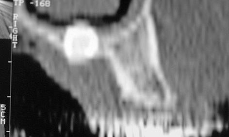
Fig 6-6d Side view of the tooth in cross section.
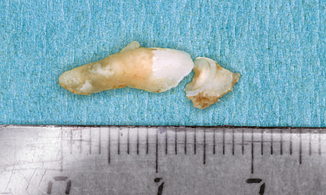
Fig 6-6e The retained tooth following extraction.
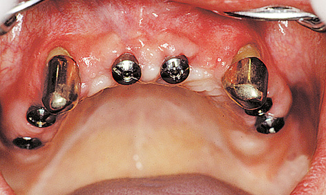
Fig 6-6f Implants following exposure, with the teeth still in situ.
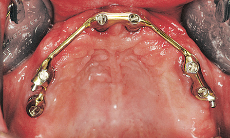
Fig 6-6g Denture with bar connector.

Fig 6-6h Retaining elements in the prosthesis.
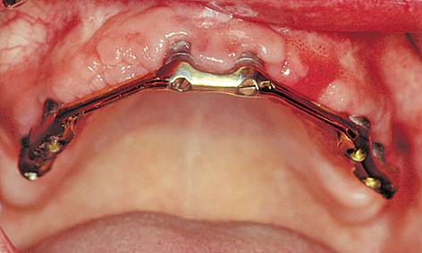
Fig 6-6i Bar connector after 5 years of functional use.
Prosthetic restoration
The canines were left in situ until the new prosthetic restoration was fabricated, so that they could continue to secure the overdenture (Fig 6-6f). Five weeks after exposure, a fabricated continuous bar connector was screwed on to the six implants (Fig 6-6g). The distal locking attachments hold the palateless denture securely in place (Fig 6-6h). The bar connector and the mucosal situation remain stable 5 years after the implants were loaded with the prosthesis (Fig 6-6i). The condition of the prosthesis is also satisfactory (Fig 6-6j). Moreover, a stable bone situation is apparent from the follow-up panoramic radiograph taken after 5 years (Fig 6-6k).

Fig 6-6j Overdenture after 5 years.
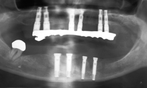
Fig 6-6k Stable bone situation at the same point in time.
Treatment course
- Extraction of the retained tooth, implant placement (1996)
- 6 months to exposure
- 5 weeks to extraction of the canines and the definitive prosthetic loading
Treatment
|
Surgery: |
Dr Christoph T. Sliwowski |
|
Prosthetics: |
Dr Michael Weber |
|
Dental technology: |
Horst Mosch |
Problems and complications
Fixed restoration with a change in implant inclination – a mechanical complication
Baseline situation
This male patient, who had already been edentulous for 15 years (Fig 6-7a), had a removable complete denture as his maxillary restoration. In contrast, the overdenture in the mandible had been stabilized with the aid of two implants and a bar. The patient wanted a fixed restoration for the maxilla. However, both maxillary sinuses showed pronounced pneumatization, so the bone supply in the anterior maxilla was very limited (Fig 6-7b).
Diagnostic tools
- Clinical examination
- Panoramic radiograph with template
- CT with template
- Dental cast analysis
Treatment plan
1.Implant placement in the maxilla and mandible
2.Exposure and definitive prosthetic loading
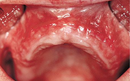
Fig 6-7a The patient’s edentulous maxilla.
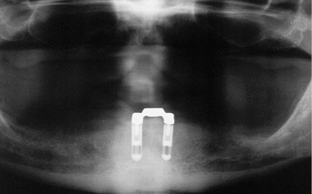
Fig 6-7b Panoramic radiograph.
Implant placement and exposure
The custom-made surgical template with the desired implant positions was fabricated in the laboratory and placed into the operation site following flap reflection (Fig 6-7c). Since the template did not stay in place securely due to the high proportion of unattached mucosa, it was stabilized further with direction indicators once the first two beds were drilled. Only then were the beds for the remaining implants drilled (Fig 6-7d).
The residual ridge had atrophied greatly during the 15 years’ use of the complete denture and was narrower than the diameter of the implants. Consequently, the implant threads were exposed on both the labial/buccal and palatal sides. Moreover, the implants had to be placed further palatally than originally planned (Fig 6-7e). Bone augmentation was performed with a mixture of Bio-Oss and bone chips, not only on the labial/buccal but also the palatal side (Fig 6-7f). Bio-Gide (Geistlich) membranes were used to cover the augmentation.
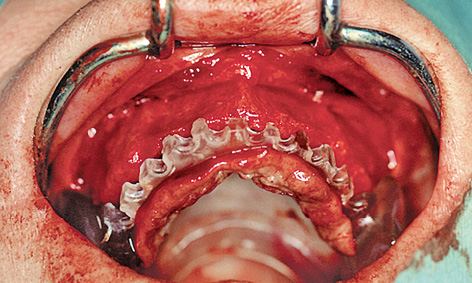
Fig 6-7c Surgical template following flap reflection.
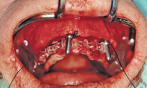
Fig 6-7d Stabilization of the template with the direction indicators.
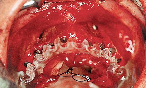
Fig 6-7e Implants inserted further palatally than planned.
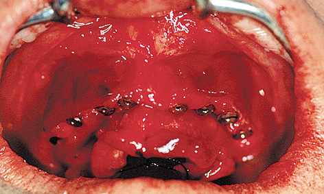
Fig 6-7f Bone augmentation.
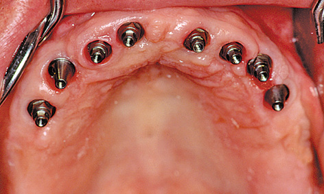
Fig 6-7g EsthetiCone abutments.
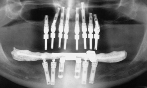
Fig 6-7h Angled abutments to correct the inclination of the implants.
Following healing and exposure, the implants were fitted with EsthetiCone and angled abutments (Fig 6-7g). The deliberate inclination of implants 13 and 25 to avoid the maxillary sinus was compensated for by using abutments angled at 17 degrees (Fig 6-7h).
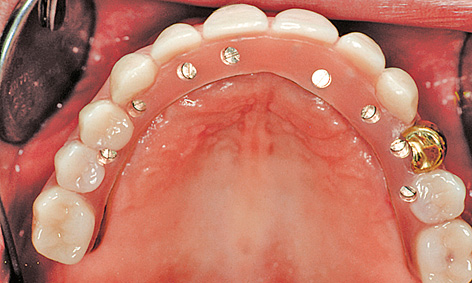
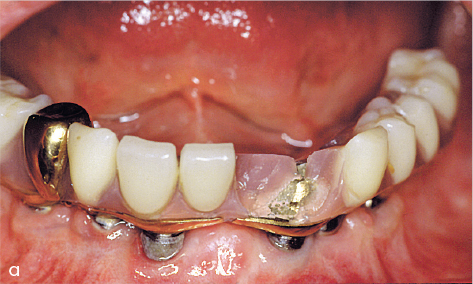
Fig 6-7i Cantilever fixed restoration screwed into place.
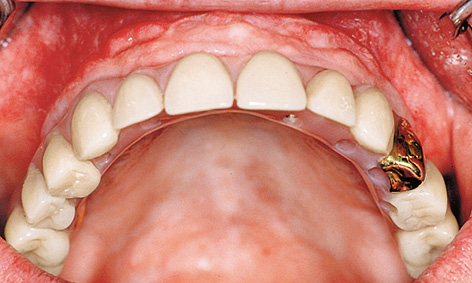
Fig 6-7j Gold crown 24 fitted at the patient’s request.
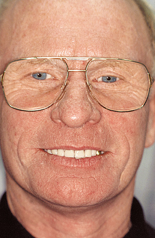
Fig 6-7k The patient 5 years after completion of the treatment.
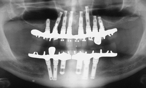
Fig 6-7l Stable bone situation at the same point in time.
Prosthetic restoration
The cantilever implant bridge replacing teeth 16 to 26 was screwed onto the implants with occlusal screws (Fig 6-7i). At the patient’s request, crown 24, like the one in his previous complete denture, was fabricated out of gold (Fig 6-7j). The patient is very satisfied with the fixed restoration of both mandible and maxilla (Fig 6-7k). The follow-up radiograph after 5 years of wear confirms a stable bone situation even in the presence of the inclined implants in regions 13 and 25 and the short 8.5-mm implant in region 15 (Fig 6-7l).
Treatment course
- Implant placement and augmentation (1996)
- 6 months to exposure
- 2 months to fabrication
Treatment
|
Surgery and prosthetics: |
Dr Christoph T. Sliwowski |
|
Dental technology: |
Horst Mosch |
Note
Mechanical complications

Patients with fixed implant-supported prostheses in both mandible and maxilla often generate enormous masticatory forces, as the restorations are very stable and can take high loads. At the same time, however, the masticatory apparatus loses most of its sensitivity (as there is no periodontal feedback), so that mechanical complications, such as fractures or the prosthesis teeth snapping off, are not uncommon (Figs 6-8a and 6-8b). This risk can be minimized if the teeth are set up in balanced articulation and all early contacts are eliminated.
Immediate loading
Immediate loading of definitive implants with NobelGuide
Baseline situation
This female patient, who had had an edentulous maxilla for many years, was having a lot of trouble with her uncomfortable complete denture. On clinical inspection, the dimensions of the residual ridge still seemed adequate (Fig 6-9a), but the tomographic imaging performed for planning purposes showed that it was narrow and that implant placement could only be considered on a conditional basis (Fig 6-9b). The patient had heard about the NobelGuide technique from an advertising campaign (Nobel Biocare) and was now insisting that this method be used for her treatment.
Diagnostic tools
- Clinical examination
- Panoramic radiograph
- Double CBCT
- NobelGuide planning
- Dental cast analysis
Treatment plan
1.Implant placement, immediate definitive prosthetic loading or long-term provisional restoration
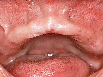
Fig 6-9a The edentulous maxilla before treatment.

Fig 6-9b 3D planning of the implants.
Preoperative preparation
Using two CBCT scans (patient with prosthesis and the prosthesis alone) as the basis, the 3D planning was carried out with the NobelGuide software. Based on the data set, a 3D template was fabricated in Sweden and sent to the clinic (Fig 6-9c). With the aid of the template, implant analogs were inserted into the definitive cast at the exact positions where implants were to be placed in the maxilla later on (Fig 6-9d). The dental prosthesis was then fabricated on the resultant cast even before the operation (Fig 6-9e). The prosthesis needed to be able to compensate for any irregularities, particularly those caused by mucosal resilience during the operation. It was to be used as a long-term provisional restoration and, in the best-case scenario, even as the definitive one. An occlusion rim was also made out of putty to ensure exact positioning of the template (Fig 6-9f).
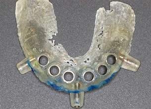
Fig 6-9c NobelGuide template.
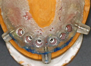
Fig 6-9d Implants placed into the definitive cast.
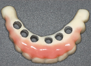
Fig 6-9e Dental prosthesis fabricated in advance.
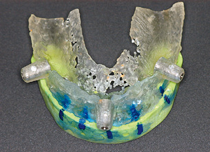
Fig 6-9f Occlusion rim used to position the template.
Implant placement and immediate restoration
Following extensive block and infiltration anesthesia (it is extremely difficult to top up the anesthesia with the template in situ), the template was placed into the mouth with the occlusion rim. To enable the relative positions of the occlusion rim to the template to be verified, vertical lines were drawn on both with a marker pen (Fig 6-9g). After the template was inserted, the patient was asked to bite down hard for a few minutes, to reduce the mucosal swelling caused by the infiltration anesthesia. With the patient still biting down lightly, three holes were drilled through the horizontal sleeves and the template secured to the jaw with three pins. After this, beds were drilled for implants 13 and 24 using sleeves that had been adjusted relative to one another, and these implants were placed. The insertion mounts were then replaced with stabilization abutments and two further implants inserted into regions 14 and 23 (Fig 6-9h). After all the implants were placed, the template was removed, showing how atraumatic this method is (Fig 6-9i). The abutments prepared in advance in the laboratory were screwed on in pairs and incorporated into the dental prosthesis with Pattern Resin (GC America) (Fig 6-9j). The completed dental prosthesis was finished and polished by the laboratory technician (Fig 6-9k) and attached to the implants in the mouth with screws. The screw access holes were provisionally sealed (Fig 6-9l). After only one operation, the patient was able to leave the clinic immediately with a fixed restoration. She was fully fit, with no pain or swelling (Fig 6-9m). The final photo shows the dental prosthesis after 4 years of functional use (Fig 6-9n).
Treatment course
- Planning and advance fabrication of the template and the dental prosthesis
- Implant placement and immediate prosthetic restoration (2005)
Treatment
|
Surgery and prosthetics: |
Dr Christoph T. Sliwowski |
|
Dental technology: |
Horst Mosch |

Fig 6-9g Occlusion rim with template in situ.

Fig 6-9h Insertion of the implants through the template.
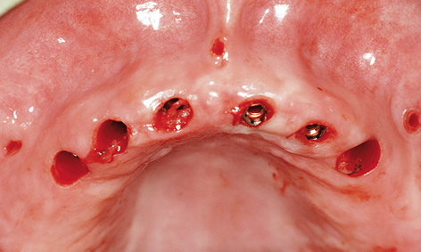
Fig 6-9i Inserted implants following removal of the template.
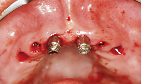
Fig 6-9j Inserting the abutments.
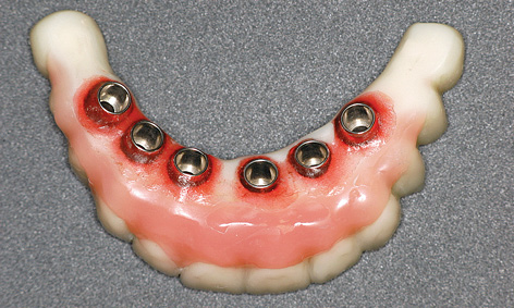
Fig 6-9k Finished prosthetic restoration prior to fitting.
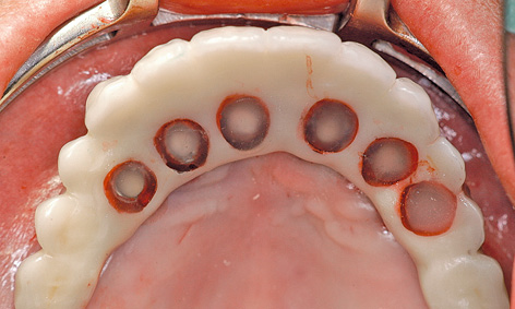
Fig 6-9l Treatment completion; the screw access holes have been sealed off.
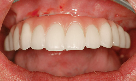
Fig 6-9m Fixed implant bridge in situ.

Fig 6-9n The same restoration after 4 years of functional use.
Note
Immediate restoration on healing abutments

Fig 6-10a Maxilla before the extraction.
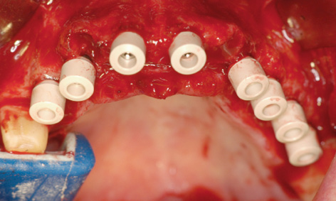
Fig 6-10b Healing abutments screwed onto the implants.
If the bone situation is good, it is sometimes possible to insert implants following extraction and load them immediately with a provisional restoration. In this sort of situation, it is an advantage if a few posterior teeth can continue to carry most of the load during the healing period, at least, and if a sufficient number of long implants can be inserted with primary stability. In the case reported here, the four anterior teeth were extracted, while the posterior teeth were left in situ (Fig 6-10a). Both extraction and implant placement took place under general anesthesia. Before the operation, the existing crowns had to be removed from the posterior teeth and the latter prepared accordingly. Here, three implants were inserted on the right side and five on the left, all with primary stability, and fitted with healing abutments directly afterwards (Fig 6-10b). Filling of the bone defect was followed by tight suturing of the wound (Fig 6-10c). The thermoplastic foil, which had been prepared in advance, was tried in. It needed to lie over the implant abutments and the patient’s own teeth without tension and be supported by the opposing dentition when the patient was biting down (Fig 6-10d). The foil was filled with a material for provisional restoration (eg, Protemp; 3M ESPE) and held in place by biting down until the material hardens. The provisional is then taken out of the foil, shaped and reincorporated (Fig 6-10e). It was attached to the teeth with provisional cement (eg, TempBond; Kerr), to avoid any hypersensitivity reactions. On the other hand, provisional cementing is usually unnecessary on healing abutments, as the retention is generally sufficient and no hypersensitivity reactions are likely. After 2 weeks, the provisional was taken out for removal of the sutures and a wound check, and was then set back into place (Figs 6-10f and 6-10g). Over the subsequent weeks, it could be replaced with a long-term provisional.
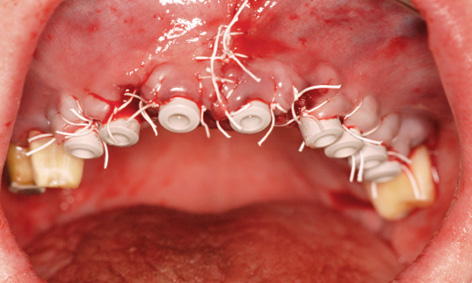
Fig 6-10c Suturing after implant placement and augmentation.
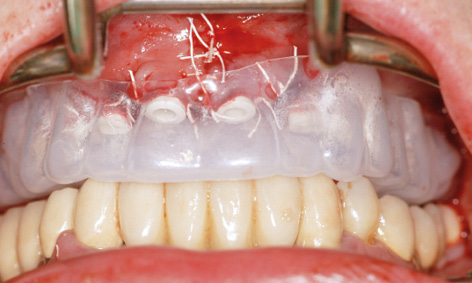
Fig 6-10d Try-in of the thermoplastic foil.
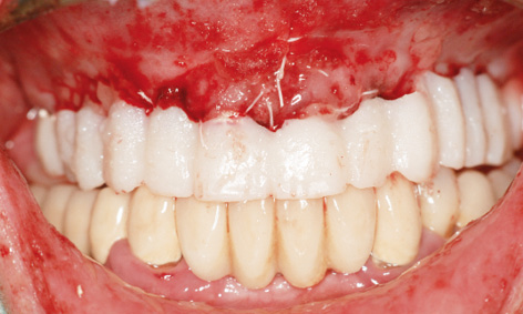
Fig 6-10e Completed immediate provisional restoration.
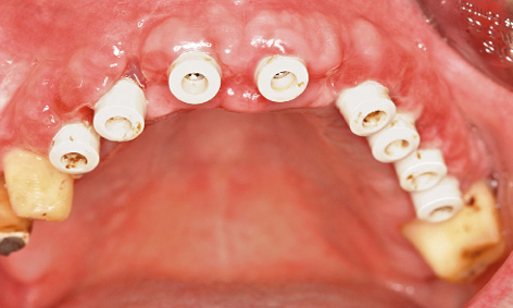
Fig 6-10f Removal of the sutures.
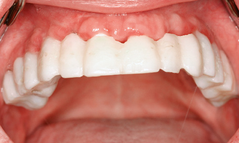
Fig 6-10g Clinical situation after 2 weeks.
Rehabilitation with reconstruction of the posterior maxilla
Considerable bone loss is often seen in the maxillary sinus due to the loss of teeth in the molar region. This bone loss progresses in the caudal and mesial directions. The technique known as sinus floor elevation, or simply sinus floor elevation, has become an established way of creating a firm “foundation” in this region (see page 383). It is a highly effective surgical procedure, enabling full prosthetic rehabilitation of the posterior maxilla to be achieved.
After bone augmentation in the posterior maxilla, where the masticatory forces are at their most powerful, implants can be placed there in accordance with static principles. In exchange, the anterior maxilla can be restored with pontics fabricated with esthetics in mind, without the use of implants. Moreover, the whole maxilla offers sufficient space for the abutments needed for a provisional restoration, whether it is supported on the patient’s own teeth or on provisional implants.
Typical treatment course
Sinus floor elevation and implant placement in a single session
Baseline situation
This female patient with an edentulous maxilla had a complete removable denture that was causing her a lot of trouble. She wanted to have a fixed or securely anchored prosthetic restoration loaded onto implants (Fig 6-11a). The residual ridge has already atrophied extensively, especially on the left side (Fig 6-11b).
Diagnostic tools
- Clinical examination
- Panoramic radiograph
- CBCT
- SimPlant planning
- Dental cast analysis
Treatment plan
1.Bilateral sinus floor elevation, implant placement and lateral augmentation
2.Exposure and widening of the zone of attached gingiva
3.Definitive prosthetic loading
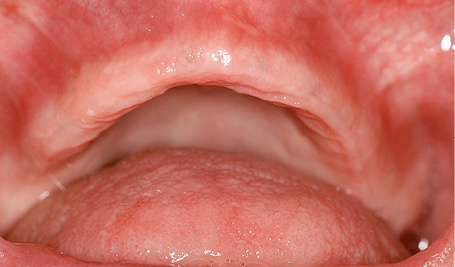
Fig 6-11a The patient’s edentulous maxilla.
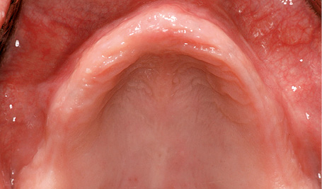
Fig 6-11b More severe atrophy on the left side.

Fig 6-11c Implantation performed concomitantly with sinus elevation.
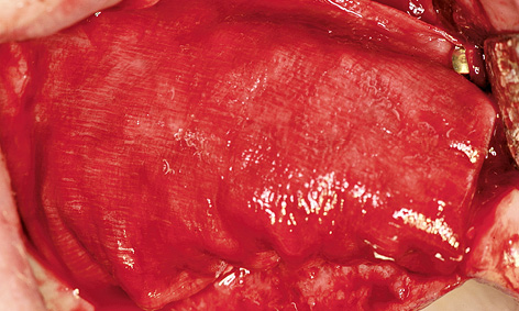
Fig 6-11d Augmentation on the right side.
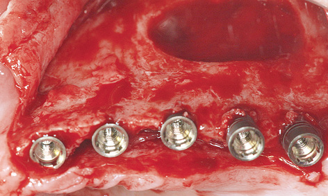
Fig 6-11e Stable insertion of the implants on the left side despite the narrow jaw.
Sinus floor elevation, implant placement and lateral augmentation
Since the dimensions of the bone in the posterior maxilla were still sufficient to anchor implants with primary stability, implant placement was performed in the same session as sinus elevation (Fig 6-11c). The maxillary sinus was prepared first, after which the implant beds were drilled and the three mesial implants fully inserted.
Initially, the two distal implants were not inserted fully. The maxillary sinus was then augmented, allowing these implants to also be inserted fully. After the cover screws were fitted, lateral augmentation was performed with harvested bone chips and Bio-Oss. The membrane was attached to the maxilla with titanium pins (Fig 6-11d). This procedure was repeated on the left side (Fig 6-11e). The residual ridge was quite narrow in the anterior maxilla, and the implants were inserted further toward the palatal direction (Fig 6-11f). The bone was also augmented over the screw threads exposed on the palatal side (Fig 6-11g). A membrane was attached with pins at the apical end and pushed under the palatal periosteum (Fig 6-11h). This was followed by saliva-proof closure of the operation site. The postoperative panoramic radiograph shows the positions of the implants and the extent of sinus elevation (Fig 6-11i).
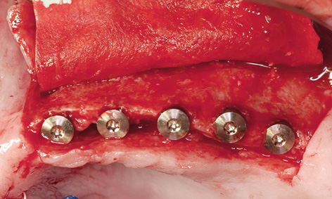
Fig 6-11f Membrane attached at the apical end.
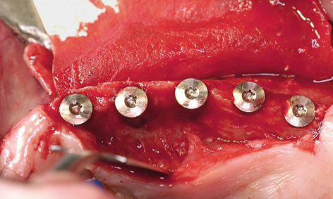
Fig 6-11g Palatal augmentation was also necessary.
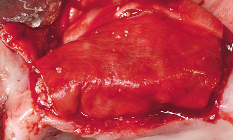
Fig 6-11h Augmentation material stabilized with the membrane.
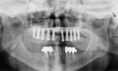
Fig 6-11i Postoperative panoramic radiograph.
Exposure
The healing period was uncomplicated and the implants were exposed 10 months after the first operation (Fig 6-11j). The residual ridge looked much wider compared to baseline, which suggests a successful augmentation (compare Figs 6-11b and 6-11k). On close inspection, however, we found that the solid substructure was covered only with unattached mucosa on the labial side (Fig 6-11l). In fact, the time of implant exposure offers the best opportunity of correcting this, by transplanting keratinized gingiva from the palate to the vestibule in the form of a pedunculated graft (Fig 6-11m). Sutures were used to bring the soft tissue of the palate much closer to the tissue surrounding the implants (Fig 6-11n). On the left side, the implants were already faintly visible through the unattached mucosa (Fig 6-11o). The incision was also made on the palate, alongside the implants (Fig 6-11p). Distal extension of the incision enabled better adaptation of the flap and made suturing easier (Fig 6-11q). Three weeks after exposure, the soft tissue situation on both sides was stable (Figs 6-11r and 6-11s). The zone of attached gingiva around the implants had a positive effect on their long-term prognosis. Direct comparison of the residual ridge at the start of the treatment and after the surgical and regenerative phase shows a marked improvement (Figs 6-11b and 6-11t), which is even more remarkable, given that the result was achieved by relatively simple means (ie, with no bone block grafts, mucosal distraction or free mucosal grafts) in only two sessions. The impression for the prosthetic restoration was taken once the correct positioning of the impression copings was checked on the radiograph (Fig 6-11u).
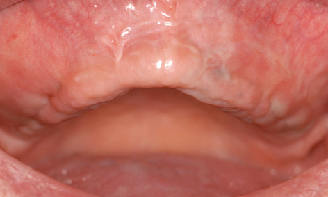
Fig 6-11j Clinical situation after 10 months.
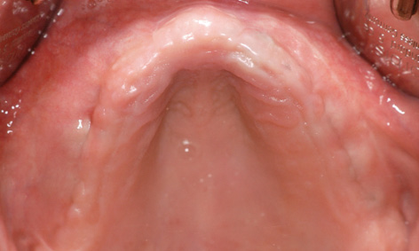
Fig 6-11k Residual ridge made wider by augmentation.
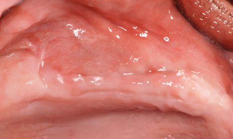
Fig 6-11l Unattached mucosa on the residual ridge.
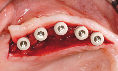
Fig 6-11m Attached gingiva gained from the palate at the time of implant exposure.
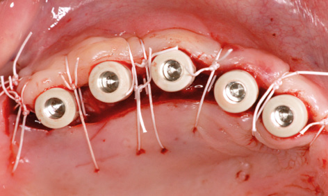
Fig 6-11n Fixing the gingiva into place with sutures.
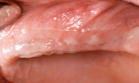
Fig 6-11o The implants shimmering through the mucosa.

Fig 6-11p Palatal incision on the left side.
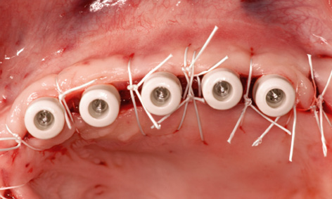
Fig 6-11q Widening the zone of attached gingiva on the left side.

Fig 6-11r Stable gingival situation after 3 weeks.
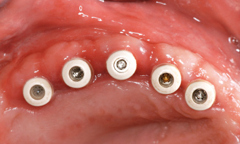
Fig 6-11s Wider gingiva on the right side.
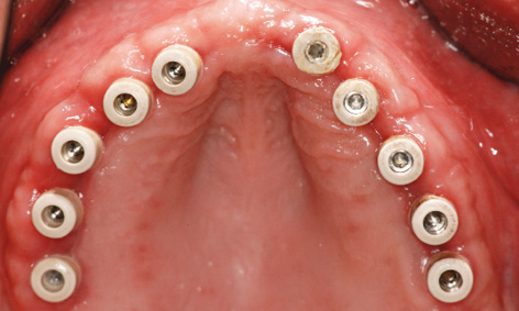
Fig 6-11t Wide residual ridge compared to baseline (Fig 6-11b).
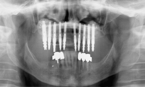
Fig 6-11u Check panoramic radiograph with the impression posts.
Treatment course
- Sinus floor elevation with implant placement and augmentation (2007)
- 10 months to exposure
Treatment
|
Surgery: |
Dr Christoph T. Sliwowski |
Typical treatment course
Severe residual ridge atrophy: sinus floor elevation and vertical augmentation prior to implant placement
Baseline situation
Originally, this female patient with an extremely atrophied maxilla had experienced a lot more problems with a loose denture in the similarly atrophied mandible; the right side was particularly badly affected. The mandibular problem had been largely resolved 5 years before the treatment of the maxilla, by means of a cantilever fixed bridge on six implants placed in the interforaminal region (Fig 6-12a). However, the continuing progression of the atrophy of the mandibular residual ridge had since caused the implants to become exposed, and the mobile mucosa around the implants may require surgical intervention.
The patient only became aware of the poor retention and fit of her maxillary denture after being fitted with her fixed mandibular restoration. A bony residual ridge is now present only in the molar region, whereas only a mobile flabby ridge remains in the anterior and premolar region (Fig 6-12b). The CBCT scan clearly shows a severely atrophied maxilla (Fig 6-12c). Only a trace of bone is visible in the anterior residual ridge on the cross-sectional image (Fig 6-12d). Pronounced malocclusion in the anterior maxilla, apparent both vertically and horizontally, was diagnosed on clinical inspection (Fig 6-12e). The vertical atrophy is particularly marked in the premolar region on the left side (Fig 6-12f). In this region, vertical augmentation was to be performed as well as sinus floor elevation (Fig 6-12g).
Diagnostic tools
- Clinical examination
- Panoramic radiograph
- CBCT
- SimPlant planning
- Dental cast analysis
Treatment plan
1.Bilateral sinus floor elevation with vertical augmentation
2.Implant placement with repeat augmentation
3.Exposure and mucosal distraction
4.Prosthetic loading

Fig 6-12a Cantilever fixed bridge in the mandible after 5 years of functional use.
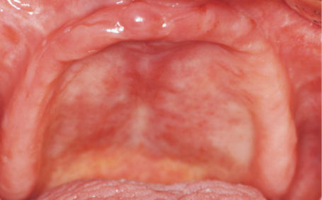
Fig 6-12b Severely atrophied maxilla with anterior flabby ridge.

Fig 6-12c 3D analysis of the maxilla.
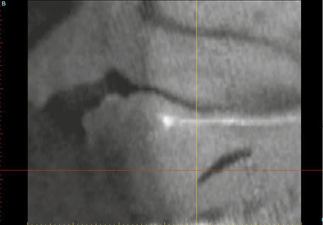
Fig 6-12d Cross section through the anterior maxilla.
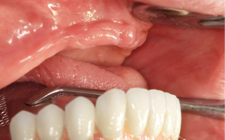
Fig 6-12e Pronounced malocclusion in the right anterior maxilla.
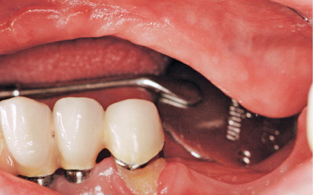
Fig 6-12f Pronounced malocclusion in the left anterior maxilla.
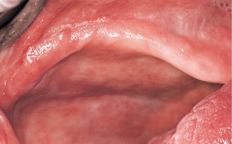
Fig 6-12g Vertical augmentation is required.
Sinus floor elevation
The first step was to perform sinus elevation on both sides of the maxilla. Titanium pins (5-mm long) (Figs 6-12h and 6-12j) were used as supports for the augmentation material and the membrane used in the vertical reconstruction of the residual ridge on the left side (at the time, it was level with the palate or even slightly below it; see Fig 6-12i). The augmentation of the cavity in the maxillary sinus and the vertical augmentation were performed with Bio-Oss and a Bio-Gide membrane. Following periosteal slitting and marked mobilization of the mucoperiosteal flap, the operation site was closed with Gore-Tex 4-0 and Mopylen 6-0 sutures (W. L. Gore and Associates and Resorba, respectively). The sutures were removed around 2 and 3 weeks after sinus elevation (Fig 6-12k).
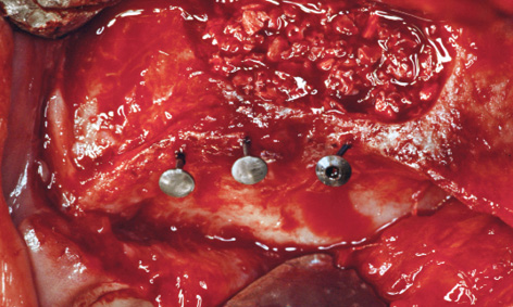
Fig 6-12h Titanium pins (5-mm long), used as vertical stops, support the membrane.
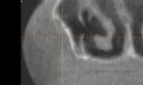
Fig 6-12i The residual ridge lies slightly below the level of the palate.
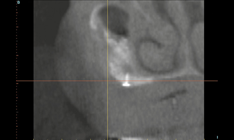
Fig 6-12j The residual ridge has been augmented by approx 4 mm in the vertical direction.
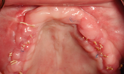
Fig 6-12k Clinical situation at the time of suture removal.
Implant placement
Because of the extreme atrophy (Fig 6-12l), a 1-year healing period was scheduled after sinus elevation and ridge augmentation, before implant placement could take place (Fig 6-12m). The gain in bone mass is clearly apparent in the 3D reconstructions (compare Figs 6-12l and 6-12m). A panoramic radiograph was taken as a check after augmentation (Fig 6-12o). Implant placement was planned using SimPlant, based on the up-do-date CBCT scan (Fig 6-12p).
The overall contours of the residual ridge (Fig 6-12n), but particularly the zones of vertical augmentation in the left premolar region (Fig 6-12q), appeared to have improved markedly relative to baseline (see Fig 6-12f). In accordance with the SimPlant planning, five implants were inserted into the augmented bone on the left side (Fig 6-12r). The right side turned out to be more problematic, as much less bone had formed there. It was only possible to insert four implants here, placing them not in line but alternately on the palatal and buccal side of the crest, to leave sufficient space between them (Fig 6-12s). This staggered placement also ensured better distribution of the masticatory forces over the prosthetic superstructure. The region was re-augmented with the harvested bone chips and Bio-Oss, followed by tight suturing. A postoperative panoramic radiograph was taken after implant placement (Fig 6-12t).
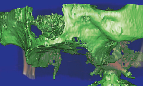
Fig 6-12l 3D reconstruction before augmentation.
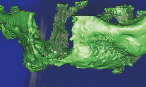
Fig 6-12m 3D reconstruction after augmentation.
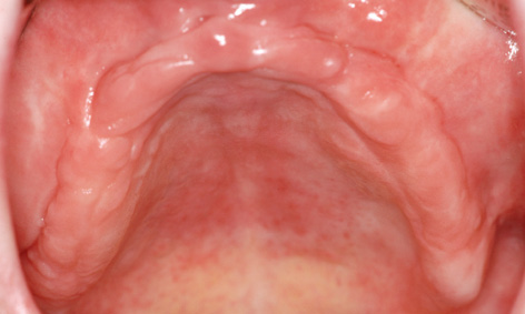
Fig 6-12n Residual ridge 1 year after augmentation.

Fig 6-12o Panoramic image after augmentation.
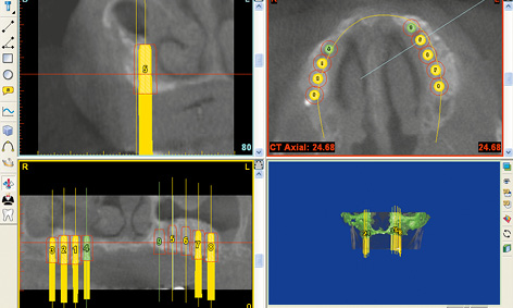
Fig 6-12p Virtual implant placement in the SimPlant program.
Fig 6-12q Considerably reduced malocclusion in the left premolar region (see Fig 6-12f).
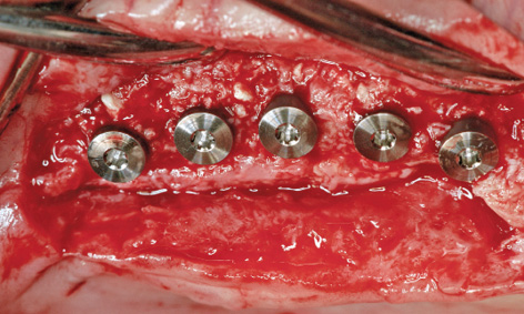
Fig 6-12r Implants in the left maxilla following insertion.
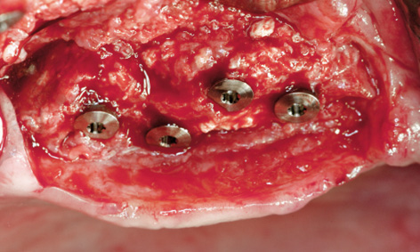
Fig 6-12s Implants placed on the palatal and buccal sides of the crest.
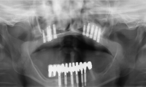
Fig 6-12t Postoperative panoramic radiograph after implant placement.
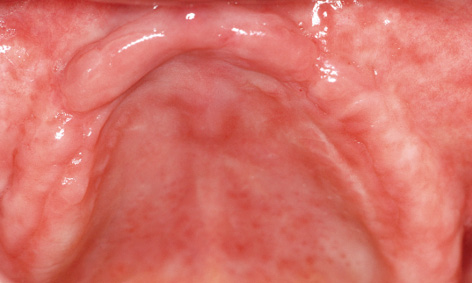
Fig 6-12u Residual ridge before exposure.
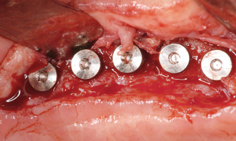
Fig 6-12v Palatal incision made for implant exposure.
Stay updated, free dental videos. Join our Telegram channel
VIDEdental - Online dental courses


