Diagnosis
Clinical examination and radiologic imaging form part of the standard diagnostic process. The clinical examination involves assessing the shape of the residual ridge and the width of the zone of attached gingiva, checking for the presence of osseous and mucosal defects and for a flabby ridge. A conventional panoramic radiograph represents the absolute minimum of basic radiologic diagnosis, but it is gradually being replaced by three-dimensional (3D) imaging investigations. Nowadays, the number of cone beam computed tomography (CBCT) scanners is increasing rapidly, and 3D diagnosis should become accessible to almost every implantologist in the near future.
3D CBCT diagnosis and SimPlant planning
The plan for this female patient was the immediate loading of a restoration on five implants directly following extraction of the four anterior teeth. A CBCT scan image was taken for the 3D planning (Fig 3-1a). The anterior part of the jaw, where the teeth were still in situ, appeared to be well preserved.
The posterior region, in contrast, was severely atrophied (Fig 3-1b). The alveolar nerves were marked on both sides to make them visible in all the imaging planes. Five implants were then planned in the interforaminal region (Fig 3-1c). The positions of the planned implants were checked in all the imaging planes and finely tuned (Fig 3-1d). Uniform distribution in the anterior residual ridge is best checked on the axial section (Fig 3-1e). The distances between the implants, and from the implants to the nerves, is to be measured in metric units. The distances between the individual implants should not be less than 3 mm, and a minimum distance of 2 mm to the nerve also needs to be maintained. The alignment of the implants was adjusted to the prosthetic requirements and to the anatomy of the jaw in the cross-sectional views. The implant in region 42 could be placed almost fully into the bone following extraction of the tooth and reduction of the residual ridge (Fig 3-1f).
This option was not available for the implant in the midline. In the coronal region, almost one third of it was exposed on the labial side (Fig 3-1g). It was the only implant for which exposed screw threads would need to be factored in at the planning stage (Fig 3-1h). When the 3D reconstruction was rotated and viewed dorsally, the same implant also showed up through the jaw (Fig 3-1i). The bone structure could be faded out for better evaluation of the relationship between the implants and the nerves (Fig 3-1j). Overall, it appeared possible to insert all five implants with good primary stability and to fit a provisional fixed implant bridge onto these implants.
For the treatment course, see page 156.
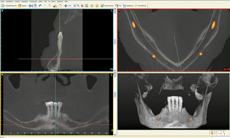
Fig 3-1a CBCT scan images of the mandible before the treatment.
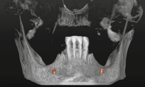
Fig 3-1b 3D reconstruction with marked nerves.
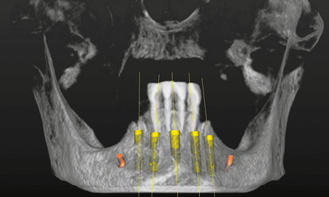
Fig 3-1c Planned implants in the 3D reconstruction.
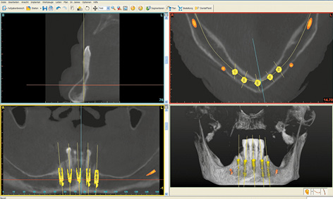
Fig 3-1d View of the implants in all the imaging planes.
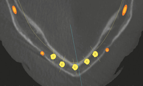
Fig 3-1e Checking the planned placement of the implants on the axial section.
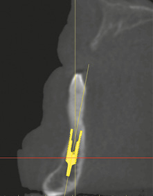
Fig 3-1f Cross-sectional view with implant 42.
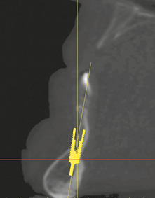
Fig 3-1g Labial bone deficit at the implant site, mid-mandible.
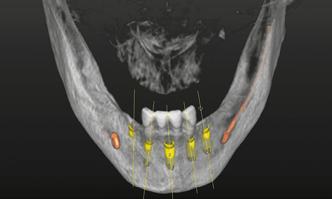
Fig 3-1h View of the 3D reconstruction with implants from the labial side.
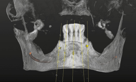
Fig 3-1i View of the 3D reconstruction with implants from the lingual side.
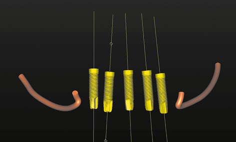
Fig 3-1j Implants and nerves with the bone faded out.
A female patient with an edentulous mandible wanted her prosthesis to be stabilized with implants. She inquired about a long-lasting, convenient prosthetic restoration avoiding prolonged treatment times. First, the extended cast denture that she had worn to date had to be replaced with a new complete denture made of acrylic, which could also act as a radiologic template.
Preparation of the prosthesis/radiologic template proceeded as usual up to the wax-up. The base of the denture needed to be extended if at all possible, including a caudal extension of the vestibular margin. After the last wax try-in, the prosthesis was remodeled into a radiologic template, by incorporating into it a few elements to act as radiologic markers. For the SurgiGuide template (SimPlant, Dentsply), these elements consist of seven to eight glass beads distributed along the line of the mandible. These beads are incorporated directly into the acrylic of the denture at the time of fabrication. They are the dark points that show through on the lingual side of the prosthesis (Fig 3-2a). Since a metal casing for the bar needs to be incorporated into the prosthesis on completion of the treatment, its position can also be virtually planned. For this purpose, the technician can make a replica of the bar casing out of a radiopaque material and incorporate it into the prosthesis at the most convenient place at his own discretion (Fig 3-2b). The desired position of the bar can then be taken into account in the planning process. Once the denture/radiologic template is fitted into the mouth, a CBCT scan of the patient is taken with the prosthesis in situ (Fig 3-2c). The prosthesis needs to be securely positioned and held in place by the opposing jaw. To be on the safe side, an occlusion record can help in the reproducible positioning of the template. A CBCT scan of the prosthesis alone was taken in parallel, and the two CBCTs were combined in the SimPlant program (Dentsply) in the double-scan mode (Fig 3-2d). The evenly distributed beads (white dots in the scan image) ensure that the prosthesis “lands” in the correct place relative to the jaw. Both nerves (inferior alveolar nerve and mental foramina) are marked before the planning. The two implants are then virtually placed into the jaw, parallel to each other with a distance of 18 mm between them.
The outline of the prosthesis (thin green line) and the opening in the bar casing replica (two vertical white bars) are very helpful when planning the first implant (Fig 3-2e). The first implant is placed slightly to the mesial side of canine 43 and aligned centrally in the mandible in the cross-sectional view (Fig 3-2f). The alignment of the implant is checked in all the imaging planes; once it has been accepted, the operator can click onto this implant with the right mouse button and onto the command “New implant at a distance of.” The operator then selects “Distance 18 mm,” followed by “Direction left” and “parallel in 3D,” and clicks on “OK.” After this, the second implant appears slightly to the mesial side of canine 33 (Fig 3-2g). Uniform, symmetric distribution of the implants can best be checked on the axial section at the height of the mental foramina (Fig 3-2h). If the positions have shifted, the second implant is deleted, the first corrected and the second newly placed using the same command. Once the positions of the implants are accepted, the next step is to plan the position of the stabilization pins. These are also planned on the cross sections: the pin is inserted through the labial margin of the prosthesis at an inclination of between 30 and 60 degrees, and extends into the bone up to the lingual cortical layer (Fig 3-2i). The two side pins are placed half-way between the mental foramen and the implant, perpendicularly to the course of the residual ridge (Fig 3-2j). The central pin is placed close to the midline. The locations of the pins in relation to the mental foramina and the implants are best evaluated on the 3D reconstruction with the bone faded out (Fig 3-2k). The overall plan is checked in all planes and projections, and then the template is ordered from Dentsply with a mouse click on “Order SurgiGuide” (Fig 3-2l). To ensure that the correct components are incorporated (bar casing replica), it is also necessary to select “Mucosa-supported” in the “Type of support” window, “Universal SurgiGuide” in “Solutions,” and “SurgiGuide for SOS Sliwowski Overdenture System” in “Comments.” The finished SurgiGuide template is delivered by package service after a few days (Fig 3-2m).
For the treatment course, see page 119.
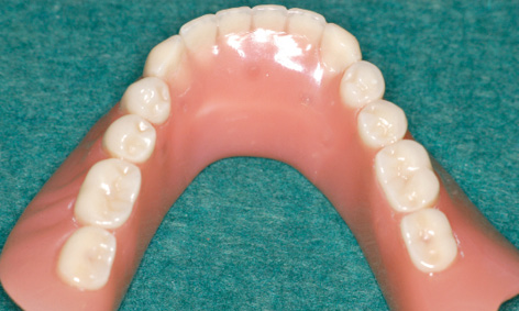
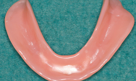
Fig 3-2b Desired position of the bar casing.
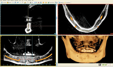
Fig 3-2c CBCT with prosthesis and marked nerves.
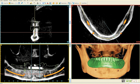
Fig 3-2d Double scan with the prosthesis.
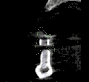
Fig 3-2e Desired position of the bar in the prosthesis outline.
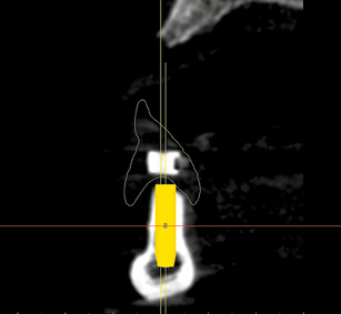
Fig 3-2f Positioning the first implant 42 to 43 while taking account of the anatomic and prosthetic aspects.
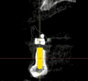
Fig 3-2g Automatic placement of the second implant 32 to 33.
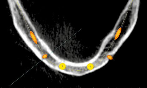
Fig 3-2h Central alignment of the two implants in the anterior region of the mandible.
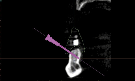
Fig 3-2i Positioning the stabilization pins.
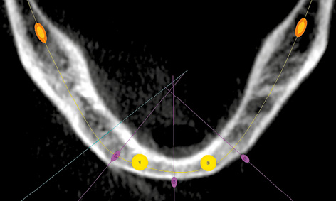
Fig 3-2j Vertical alignment of the pins relative to the residual ridge.
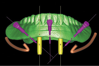
Fig 3-2k Collision check.
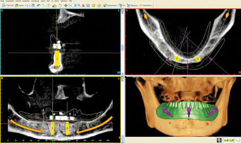
Fig 3-2l Completed SimPlant planning needed to order the SOS SurgiGuide template.
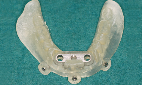
Fig 3-2m Completed SOS SurgiGuide template.
Note
Extremely narrow mandible
Fig 3-3a Panoramic radiograph showing nothing of note, adequate bone height.
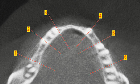
Fig 3-3b Marked locations of the cross sections on the axial section.
Cross sections in the following regions:
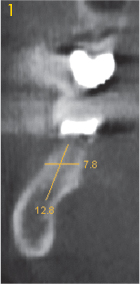
Fig 3-3c Right molar.
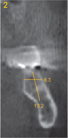
Fig 3-3d Left molar.
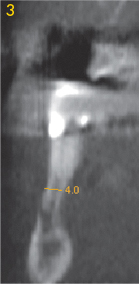
Fig 3-3e Right premolar.
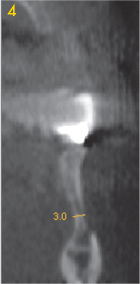
Fig 3-3f Left premolar.
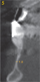
Fig 3-3g Right canine.
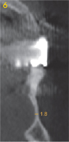
Fig 3-3h Left canine.
In rare cases, the mandible can be very narrow, a feature that is not normally visible on the panoramic radiograph (Fig 3-3a). However, the width of the residual ridge can be precisely determined if a CT or CBCT scan is available (Fig 3-3b). In the present case, the panoramic radiograph taken following implant treatment in the maxilla indicated no suspicion of an unsatisfactory bone situation in the mandible (Fig 3-3a). Analysis of the cross sections shows that the residual ridge is relatively wide in the molar region (Figs 3-3c and 3-3d), but already shows marked narrowing in the premolar region.
Above the mental foramen, the residual ridge is already so narrow – 3 and 4 mm respectively – as to require augmentative measures (Fig 3-3e and 3-3f). The situation in the anterior and canine regions looks even more problematic: here the residual ridge is less than 2 mm wide, allowing no implants to be placed in this segment (Fig 3-3g and 3-3h). Extensive augmentation is necessary before any implant placement can take place. In this situation, implant placement based on diagnosis by panoramic radiograph alone would inevitably lead to unexpected intraoperative problems.
Rehabilitation with implant placement only in the interforaminal region
The interforaminal region is the most convenient and most comfortable part of the oral cavity for implant placement. The following factors contribute toward this: no limiting anatomical structures on the downward side (apart from the mental foramina); good access and good view during the procedure; good bone quality; and, almost always, a good bone supply to anchor the implants. For this reason, all the implantology statistics show the highest success rates in this region.
In the interforaminal region, if bone quality and quantity are good, immediate functional loading with a prosthetic restoration is almost always possible. Apart from ensuring that the optimal anatomic relationships are in place, the following conditions also need to be fulfilled:
- Long (15 to 18 mm), securely inserted implants (at least 40 N/cm, preferably bicortical support)
- Immediate primary interlocking of the implants (within a maximum of 48 h)
- No retention forces if using removable dentures
- No extensions if using fixed dentures
- Prosthesis adjusted for cuspless occlusion.
Several options are available for prosthetic restoration of the edentulous mandible, all of them offering a good prognosis, well-established through prolonged clinical use. A removable denture requires two or four implants in the interforaminal region. The prosthesis can be fitted via connecting bar, magnetic, ball or telescopic attachments. The author has developed a special overdenture system, the Sliwowski Overdenture System (SOS), supported on two implants and a prefabricated bar; this is presented in detail on pages 114–115.
Four to six interforaminal implants are needed for a cantilever fixed partial denture. A maximum of 12 teeth can be replaced with this type of prosthetic restoration (up to the first molars). This represents a very acceptable solution for the great majority of patients, as regards both occlusal function and esthetic aspect.
A fixed provisional restoration fitted on the day of implant placement itself is also an option, achieved by inserting additional, provisional implants. Alternatively, immediate loading of definitive implants with a prosthesis can be achieved with a variety of treatment concepts, eg, Brånemark System Novum, NobelGuide, the Teeth-in-an-hour implant system (Nobel Biocare) and SurgiGuide (Dentsply) or SOS. As an alternative to these technically very complex methods, an immediate prosthesis can also be provided by taking an impression directly after the operation and fabricating an immediate provisional denture. This provisional can then be worn until the definitive prosthesis is fabricated.
Removable prostheses on two implants
Typical treatment course
Removable immediate prosthesis on two implants and one prefabricated bar – the SOS method
Baseline situation
After losing her last teeth, a female patient with an edentulous mandible had been wearing a relined overdenture, which had long been obsolete. She was interested in an implant-supported restoration, but was afraid of the surgery and the high cost involved. Her wish was for a stable restoration, ideally immediately and at a reasonable price. The patient has heard about the SOS method, which would meet her expectations. After the clinical examination, it was decided to start with the preparation (Fig 3-4a). To begin with, this involved fabricating a full mandibular denture, which was also to act as a radiologic template.
For the SimPlant planning and fabrication of the SOS template, see diagnosis section on page 114.
Diagnostic tools
- Clinical examination
- Fabrication of the new prosthesis (template)
- CBCT with the prepared template/prosthesis
- SimPlant planning required to order the SOS template
Treatment plan
1.Planning and ordering the SOS template
2.Insertion of two implants with the aid of the template and fitting of the bar, impression taking and incorporation of the definitive prosthesis
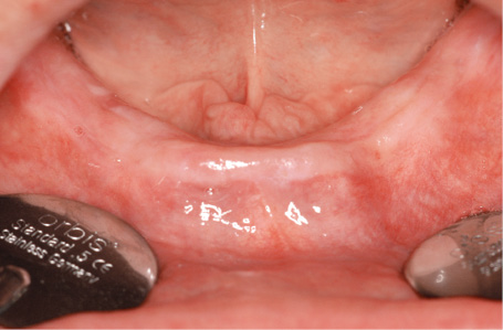
Fig 3-4a The edentulous mandible before the treatment.
Implant placement
The stable positioning of the template on the residual ridge and its relation to the dentition of the opposing jaw was first checked (Fig 3-4b). The mandible was then numbed with bilateral block anesthesia and infiltration in the interforaminal region.
Attention: The anesthesia has to take 100% effect, as any top-up is very difficult once the template has been fitted into place.
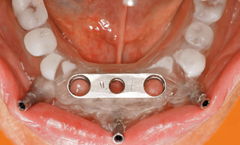
Fig 3-4b Try-in of the SOS template.
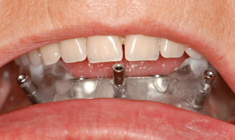
Fig 3-4c Stabilization of the template by the opposing dentition.
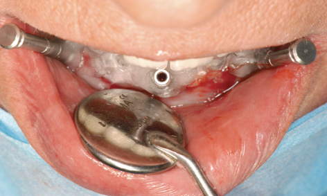
Fig 3-4d Horizontal bores for the stabilization pins.
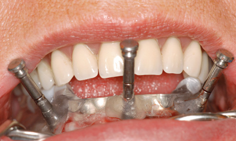
Fig 3-4e Securing the template with three pins.
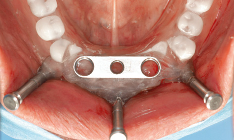
Fig 3-4f Bar casing replica positioned exactly over the residual ridge.
The template was put back into the mouth, and the patient advised to bite down hard for a few minutes (Fig 3-4c). The pressure exerted by the template compressed the swelling due to the anesthetic, positioning the template more securely onto the jaw. The patient was covered with sterile drapes, after which the procedure could start. With the patient biting down, the first step was to drill three horizontal bores for the stabilization pins, working with a 1.5-mm spiral bone drill through the surgical template sleeves: first right and left, then in the middle (Fig 3-4d). All three pins were inserted up to the endpoint (Fig 3-4e). The patient could now open her mouth and the complete maxillary denture was removed. Stable positioning of the template was checked, after which preparation of the implant beds through the drill guides could begin (Fig 3-4f). Several drill guides (Fig 3-4g) of increasing diameter (from 1.5 to 3.4 mm) were available, which were screwed onto the bar casing replica (Fig 3-4h).
The bar casing replica sits firmly in the template and determines the planned positions of the implants in the jaw. Bores were drilled through the drill guides using the following spiral bone drills in succession: 1.5, 2.0, 2.8, 3.0 and 3.2 mm; the 3.4 mm drill was also used for hard bone (Fig 3-4i). After each bore was drilled, a vertical pin of the same diameter was inserted into the double surgical guide, the added stabilization ensuring even greater precision when drilling the second bore (Figs 3-4j and 3-4k).
Attention: The vertical pins are also needed to check the implant bed: after the drilling and removal of the double drill guide, they are inserted into the implant bed and moved in the labiolingual direction (Fig 3-4l). If no movement is possible, this means that the implant bed is in the bone. If the pin moves, then something is wrong with either the template or the preparation, and implant placement can only continue following flap reflection, with the surgeon working under visual control.
After drilling with largest diameter drill of 3.2 mm (or 3.4 mm if the bone is hard), the implants were inserted through the template (Fig 3-4m). Implant placement can be carried out with a variety of systems, and special SOS implants are available from Osteoplant (Fig 3-4n). The implants are first driven in by hand or with a powered device up to a torque of 40 N/cm (Fig 3-4o). The insertion continues with a manual ratchet (Fig 3-4p), until the insertion posts are fully sunk into the casing replica (Fig 3-4q).
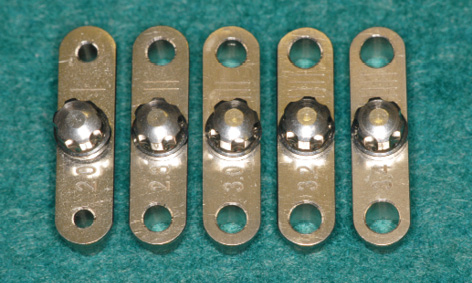
Fig 3-4g Double drill guides used for preparation of the implant bed.
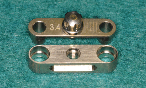
Fig 3-4h Each drill guide was screwed onto the bar casing replica.
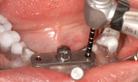
Fig 3-4i Bore drilled with the 2-mm spiral drill.
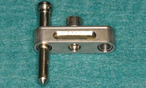
Fig 3-4j Stabilization of the drill guide with the vertical pin.
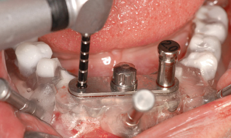
Fig 3-4k The vertical pin is inserted into the first bore followed by drilling of the second.
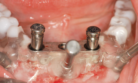
Fig 3-4l Checking stability with the pins.
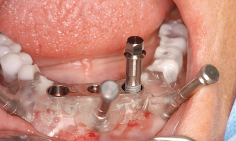
Fig 3-4m Insertion of one implant.
Fig 3-4n The SOS implant from the Polish manufacturer Osteoplant, Poznan’ (available from: www.osteoplant.com.pl & www.system-sos.com).
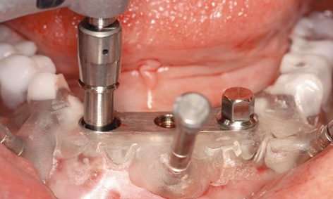
Fig 3-4o The implant can first be driven in with a powered device to ensure torque control.
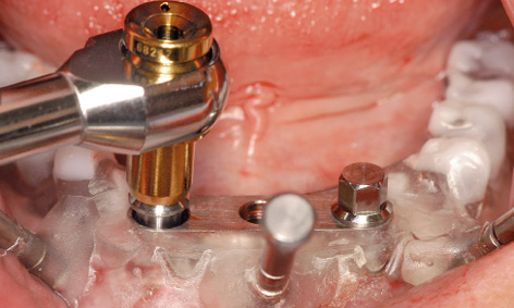
Fig 3-4p The insertion continues with the manual ratchet.
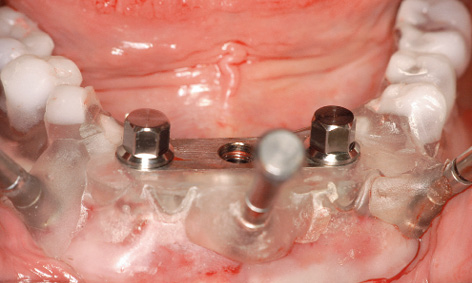
Fig 3-4q Both implants have been driven in up to the endpoint.
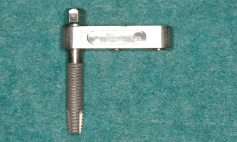
Fig 3-4r The implant with insertion post in relation to the bar casing replica.
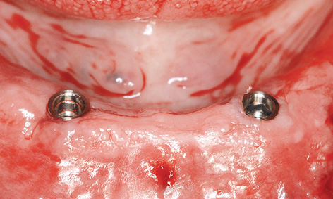
Fig 3-4s Inserted implants following removal of the template.
When the insertion post has been sunk into the replica up to its endpoint, the implant lies just below the lower edge of the replica, ie, ideally in its final position (Fig 3-4r). The insertion posts and horizontal pins were then removed and the template taken out (Fig 3-4s). If the insertion posts jam in the replica, they should be turned very slightly to the left with the ratchet and taken out once the tension is released. If the implants are still above gingival level, they are driven in further with the manual ratchet (using the same number of turns for both implants) until they are flush with the gingiva. In addition to a visual check, the position of the implants can also be verified using the bar with the abutments inserted (Fig 3-4t).
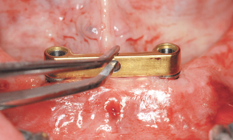
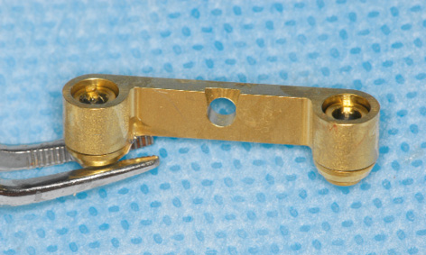
Fig 3-4u The abutments are held onto the bar with chlorhexidine gel.
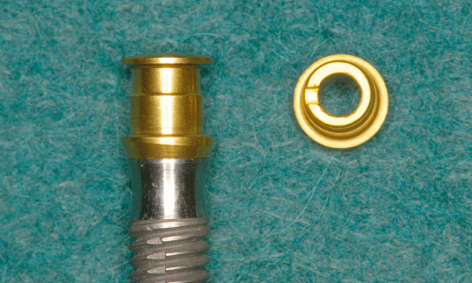
Fig 3-4v The EBF (Eccentric Bar Fixation) abutment is off the implant axis by 0.2 mm.
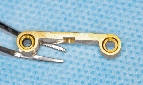
Fig 3-4w The abutments are aligned with the notches pointing in the labial direction.
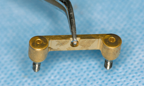
Fig 3-4x Abutments, screws and bar are held together with chlorhexidine gel.
The bar can be prepared for this by slotting the abutments into the channels from below, eg, with the aid of chlorhexidine gel, and aligning the notches (Fig 3-4u).
Attention: The EBF (Eccentric Bar Fixation) abutments are constructed so that they can compensate for small deviations of up to 0.4 mm. They are eccentric, being 0.2 mm off the implant axis and the direction is marked with a notch (Fig 3-4v). This notch allows them to be turned with an instrument. If the distance between the implants is very slightly greater than 18 mm, the notches point inwards. If it is less than 18 mm, they point outwards. If it is exactly 18 mm, they point forwards, to position the bar towards labially as far as possible (Fig 3-4w).
The bar with the aligned abutments is placed onto the implants with forceps (Fig 3-4x) and fastened with screws (Fig 3-4y). The definitive alignment of the abutments can be fine-tuned alternately on the two implants, taking out first one screw and then the other. The precise fit of the abutments needs to be checked from both labial and lingual aspects with magnifying glasses and a probe (Figs 3-4z and 3-4aa), before the screws are tightened with a 30 N/cm torque. During the operation, the technician can ream out the prosthesis in the region of the bar, so that it can be used as a customized tray for taking an Impregum (3M ESPE) impression (Fig 3-4bb). To ensure that the modeling compound does not escape from the prosthesis, the adhesive coating is supplemented with a number of lingual and labial retention holes. The impression is taken with the mouth closed and the mandibular prosthesis is held in place by the teeth of the opposing jaw (Fig 3-3cc).
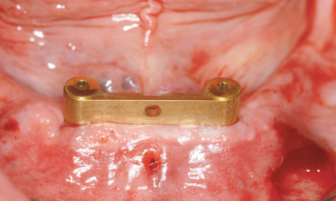
Fig 3-4y Bar fitted directly after implant placement.
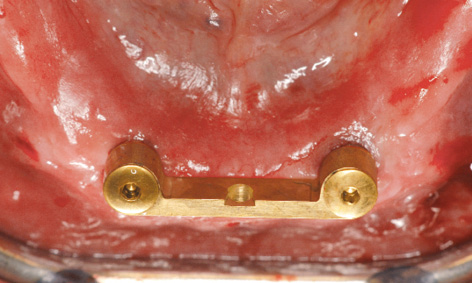
Fig 3-4z Occluso-lingual view of the bar.
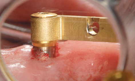
Fig 3-4aa Checking the fit of the abutments.
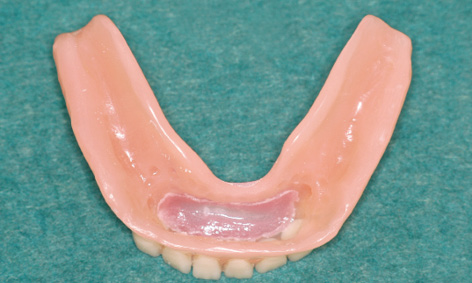
Fig 3-4bb Reamed-out prosthesis as an impression tray.
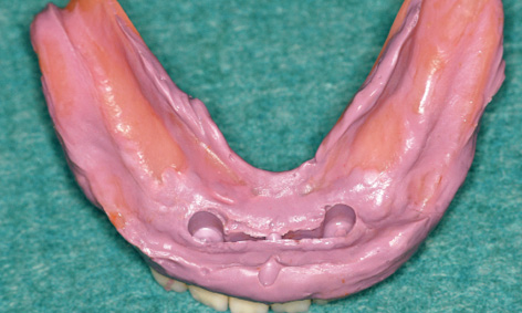
Fig 3-4cc Taking an impression with Impregum.
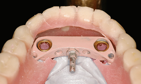
Fig 3-4dd Incorporating the bar casing into the prosthesis in the laboratory.
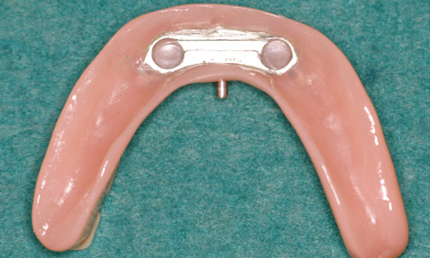
Fig 3-4ee Finished prosthesis with integrated casing.
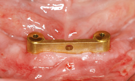
Fig 3-4ff Operation area after 1 day.

Fig 3-4gg Happy patient on the next day.
Prosthetic loading
In the laboratory, a definitive cast was made from the impression and the casing replica was incorporated into the available prosthesis (Fig 3-4dd). The finished prosthesis could be fitted into the patient’s mouth after approximately 2 to 3 h (Fig 3-4ee). In the present case, the fitting took place on the following day. The wounds caused by the pins were already healing, but slight gingival swelling developed overnight, so that the patient first had to bite down hard with the prosthesis for a few minutes before the MK1 attachment could be locked into place. The patient experienced no pain, there was no bleeding and the swelling was also minimal, so that she looked radiantly happy the day after the operation (Fig 3-4gg). She was instructed to wear the prosthesis for 1 to 2 days without removing it, before starting to practice using the locking attachment herself. She could unlock the attachment with the MK1 key (Fig 3-4hh).
Placing an index finger under her tongue, she can lock the prosthesis onto the bar (Fig 3-4ii). After 1 year of use, all is well with the bar (Fig 3-4jj) and the patient is delighted that her denture stays in place so securely.
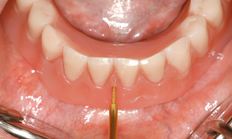
Fig 3-4hh Opening the locking attachment with the key.
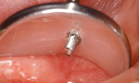
Fig 3-4ii Unlocked attachment. The prosthesis can now be removed.
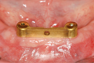
Fig 3-4jj Clinical situation after 1 year.
Treatment course
- One-step treatment (2011)
Treatment
|
Surgery and prosthetics: |
Dr Christoph T. Sliwowski, Dominika Sliwowska, DDS |
|
Dental technology: |
Dental technician Ludger Janssen, DentaLab |
Notes on the SOS method
The SOS method presented here offers the following advantages:
1.The retention system is compatible with most leading implant systems, such as Neoss, the Brånemark System, Replace, Osteoplant, Straumann, 3i and Generica.
2.The prefabricated components offer high quality and a precise fit, which are difficult to achieve in traditional prosthetics.
3.The locking of the prosthesis onto the bar guarantees a high degree of wearer comfort and protects against an unwanted loss of stability.
4.The whole treatment can be done in 1 day.
5.Implant placement involves a virtually atraumatic surgical procedure of approximately 15 to 20 mins; swelling and postoperative pain are minimal.
6.The costs are considerably reduced compared to conventional methods.
7.The technique is easy to master, for both dentist and patient.
8.Mechanical or biological complications (from denture sores to implant loss) are very rare.
Atypical treatment course – problematic baseline situation
Treatment of an extremely narrow residual ridge with the SOS method
Baseline situation
This 58-year-old woman was experiencing considerable suffering due to a barely retained denture in her edentulous mandible (Fig 3-5a). In the panoramic radiograph, the residual ridge appeared to be suitable for implant placement.
Diagnostic tools
- Clinical examination
- Panoramic radiograph
- CBCT with template
- med3D planning
- Surgical 3D template
Treatment plan
1.Fabrication of the 3D template
2.Implant placement
3.Direct definitive loading
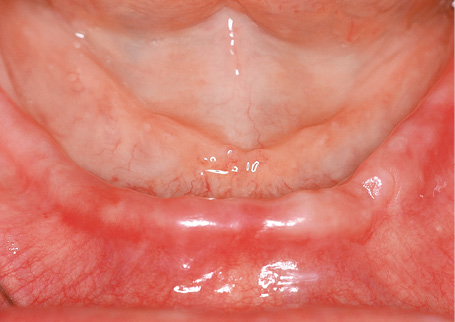
Fig 3-5a The edentulous mandible before the treatment.
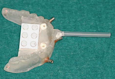
Fig 3-5b Template for the med3D planning program with integrated Lego block.
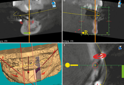
Fig 3-5c Planning the position of implant 33.
Planning and implant placement
Implant placement was planned using the med3D program. This program requires a Lego block to be integrated into the template as a reference (Fig 3-5b). Only the CBCT scan revealed how problematic implant placement in the anterior mandibular region would be. Vertically, there is sufficient space for long implants; the problem lies in the horizontal dimension of the residual ridge. In cross section, it is obvious that there is hardly any space for a thin, 3.5-mm implant in the region of tooth 33 (Fig 3-5c). There is a very similar situation in region 43 (Fig 3-5d).
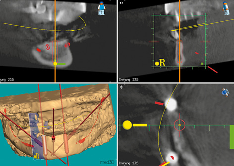
Fig 3-5d Planning the position of implant 43. The residual ridge is extremely narrow at both sites (see Fig 3-5c).
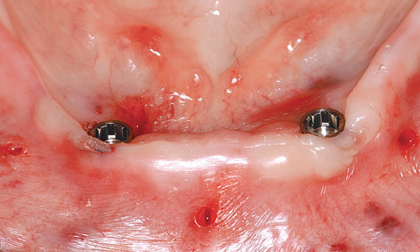
Fig 3-5e The implants directly after insertion.
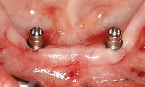
Fig 3-5f The abutments have been screwed into place.
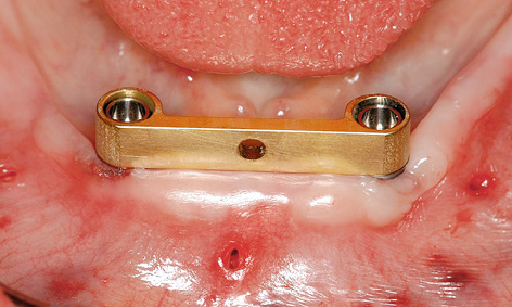
Fig 3-5g SOS bar fitted onto the abutments.
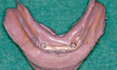
Fig 3-5h Taking an impression with the available prosthesis.
Attention: This very important diagnostic information cannot be read from the panoramic radiograph, but can only be obtained from 3D images (CBCT, CT). In such extreme situations, navigated insertion requires a template with almost 100% precision. Both the treatment provider and the patient need to be clear about the high risk involved.
Implant placement proceeded without any problems, with the implants successfully inserted into the correct position and to the planned depth (Fig 3-5e). The abutments were screwed onto the implants. Once the bar was fitted (Fig 3-5g), an impression was taken using the reamed-out prosthesis, with the bar remaining embedded in the modeling compound (Fig 3-5h). The prosthesis was reshaped in the laboratory and fitted immediately (Fig 3-5i). Figure 3-5j shows the clinical situation 6 months after the treatment was completed. A panoramic radiograph was also taken at this point, confirming a stable bone situation around the implants (Fig 3-5k).
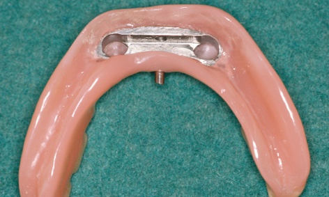
Fig 3-5i Underside of the prosthesis following incorporation of the bar casing.
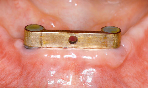
Fig 3-5j Fitted bar after 6 months of functional use.
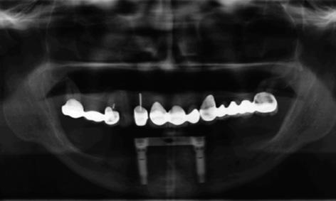
Fig 3-5k Follow-up panoramic radiograph after 6 months.
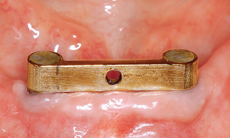
Fig 3-5l Clinical situation after 2 years.
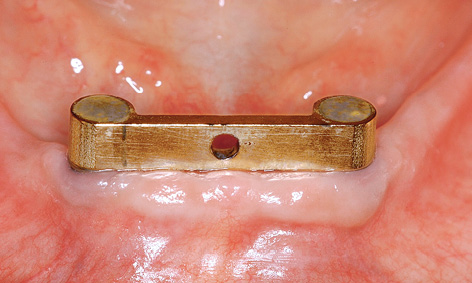
Fig 3-5m Clinical situation after 3 years.
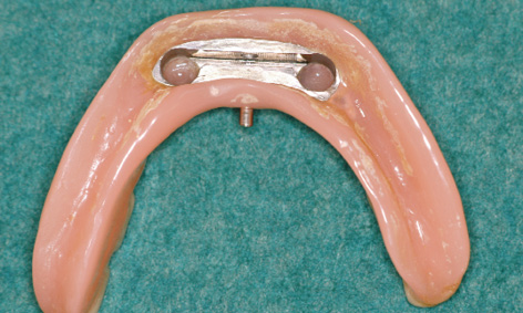
Fig 3-5n Deposits on the prosthesis after 3 years of functional use.

Fig 3-5o Satisfied patient 3 years after the treatment.
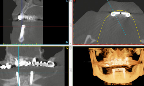
Fig 3-5p CBCT scan images after 3 years.
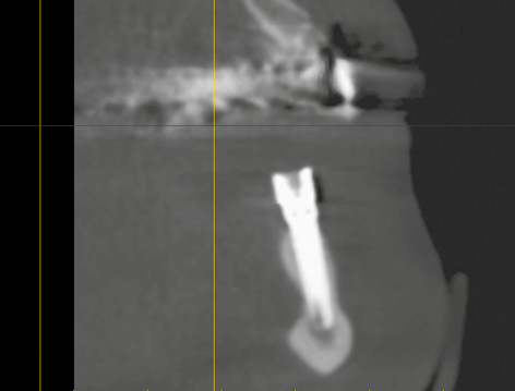
Fig 3-5q Bone situation around implant 33 after 3 years, in the cross section generated from the CBCT scan.
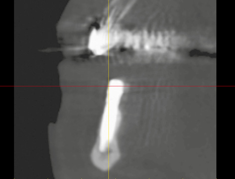
Fig 3-5r Bone situation around implant 43 at the same point in time.
Figures 3-5l and 3-5m show the clinical situation after 2 and 3 years of functional use. Deposits are visible on the prosthesis after 3 years: these were difficult for the patient to reach and were removed in the laboratory (Fig 3-5n).
The patient was very satisfied with the outcome of her treatment (Fig 3-5o). Another CBCT scan was performed after 3 years due to the impending restoration of the maxilla (Fig 3-5p). This opportunity was taken to check the bone situation around the implants in the mandible. The implant in region 33 had been inserted as planned and had integrated into the bone (Fig 3-5c and 3-5q). Implant 43 provides further confirmation of the high precision of the med3D template (Fig 3-5d and 3-5r).
Treatment course
- One-step treatment (2008)
Treatment
|
Surgery and prosthetics: |
Dr Christoph T. Sliwowski |
|
Dental technology: |
Dental Technician Ludger Jansen, DentaLab |
Atypical treatment course – problematic baseline situation
SOS with osteoplasty and augmentation
Baseline situation
This 60-year-old woman was experiencing considerable suffering from an edentulous mandible. The residual ridge was very narrow and the prosthesis, even when retained with adhesive, did not stay in place for long (Fig 3-6a). The panoramic radiograph shows a jaw of sufficient height, suitable for 18-mm implants (Fig 3-6b). Only the CBCT scan reveals that the ridge is knife-edged and not suitable for transmucosal implant placement without additional intervention (Fig 3-6c). The sharp edge is to be reduced by approximately 7 to 8 mm (Fig 3-6d).
Diagnostic tools
- Clinical examination
- Panoramic radiograph, CBCT with template
- SimPlant planning
- Surgical 3D template
Treatment plan
1.Fabrication of the SOS template
2.Implant placement
3.Osteoplasty with augmentation
4.Direct definitive loading
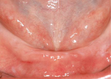
Fig 3-6a Narrow residual ridge of the edentulous mandible.
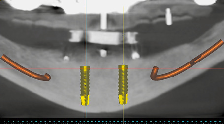
Fig 3-6b Panoramic section with the planned implants.
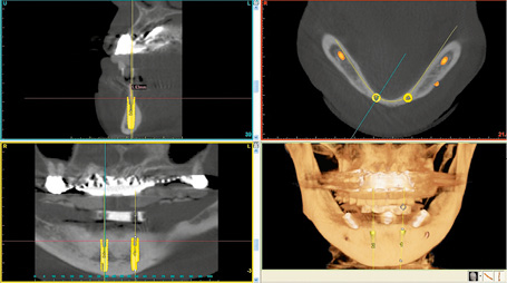
Fig 3-6c 3D diagnosis and SimPlant planning for the SOS template.
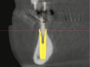
Fig 3-6d The sharp edge of the residual ridge needs to be reduced.
Fig 3-6e Positioning the template with an interocclusal record.
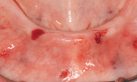
Fig 3-6f Prepared implant beds following removal of the template.
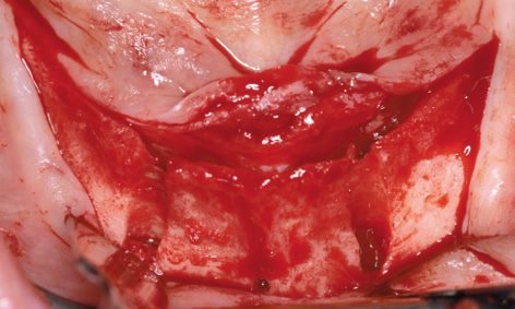
Fig 3-6g Knife-edge residual ridge.
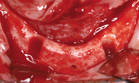
Fig 3-6h Residual ridge following osteoplasty.
Implant placement with osteoplasty
Working under bilateral conduction and infiltration anesthesia, the template was positioned into the mouth under the occlusal record rim (Fig 3-6e). The template was first stabilized with the horizontal pins and the two implant beds were then prepared through the template. Once preparation was completed with the last spiral drill (3.2 mm), the template was removed from the mouth (Fig 3-6f). The incision was made centrally over the residual ridge, with a releasing incision at the front, and the lingual and labial flaps were dissected away (Fig 3-6g). The knife-edge residual ridge was reduced to a uniform plateau (Fig 3-6h), and a bone filter was used to collect the resultant bone chips, to be used for the augmentation. The height of the reduction can be assessed using the perforation made by the horizontal pin (compare Figs 3-6g and 3-6h).
The implants were inserted into the transmucosally prepared beds. Since they were located a bit further labially, several of the threads were exposed (Fig 3-6i). Once the implants were adjusted to the same height, the bar was screwed onto the eccentric abutments and the screws tightened with a 30 N/cm torque (Fig 3-6j). The labial augmentation was performed with the harvested bone chips and the operation area closed with sutures (Fig 3-6k). The postoperative panoramic radiograph shows the correctly positioned implants (Fig 3-6l).
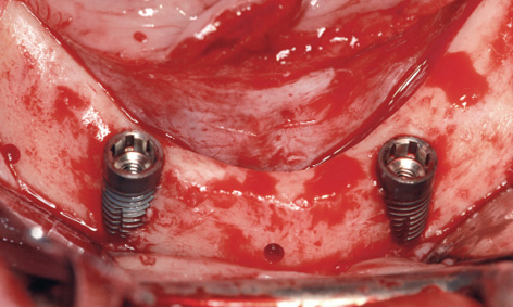
Fig 3-6i Inserted implants.
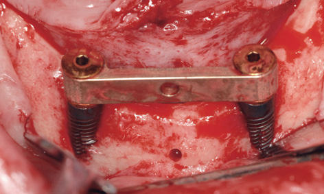
Fig 3-6j SOS bar fitted into place.
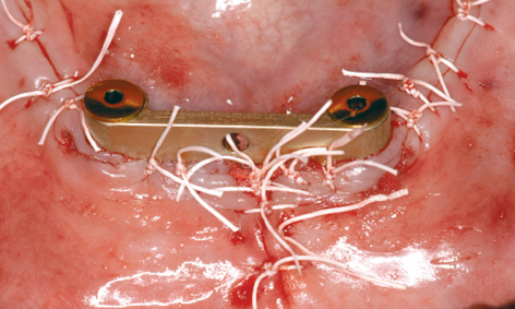
Fig 3-6k Closure by suturing after augmentation.
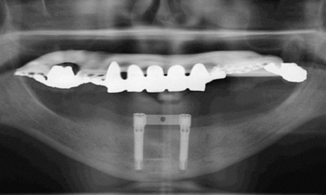
Fig 3-6l Postoperative panoramic radiograph.
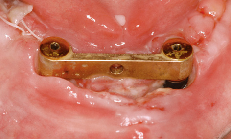
Fig 3-6m Dehiscence following removal of the sutures.
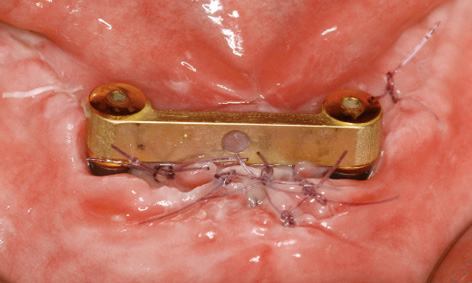
Fig 3-6n Re-suturing.
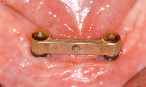
Fig 3-6o Closure of the dehiscence after 1 month.
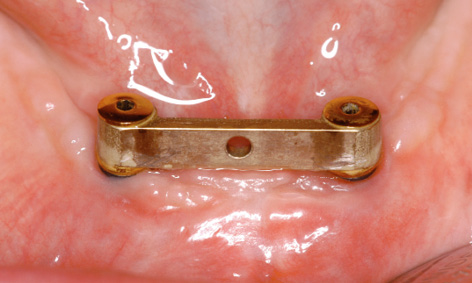
Fig 3-6p Clinical situation after 2 years.
Complication – wound dehiscence
The sutures were due to be removed 1 week after implant placement. At that point, we found that the sutures had torn in the middle, resulting in wound dehiscence under the bar (Fig 3-6m). The wound margins were refreshed with the scalpel and adapted with new sutures. After 1 more week, the wound closure appeared to have stabilized (Fig 3-6n). A few days later, it also proved possible to remove the remaining sutures. The dehiscence had healed completely after 2 more weeks (Fig 3-6o). Two years later, the mucosal situation was stable and no traces of the dehiscence remain (Fig 3-6p).
Treatment course
- One-step treatment (2010)
Treatment
|
Surgery and prosthetics: |
Dr Christoph T. Sliwowski, Dominika Sliwowska, DDS |
|
Dental technology: |
Dental Technician Ludger Jansen, DentaLab |
Atypical treatment course – problematic baseline situation
Immediate implant placement following extraction and direct loading with SOS without a template
Baseline situation
A 70-year old man had six teeth remaining in the anterior mandible, but these could not be preserved in the long term (Fig 3-7a). He had heard of the SOS technique and was expressly requesting this type of prosthetic restoration, preferably as quickly as possible. He was skeptical and negative about the suggestion that he could be fitted with an overdenture resting on his remaining teeth. A CBCT scan was taken for the treatment planning and the option of inserting two implants for the SOS bar was verified (Fig 3-7b). At the patient’s request, the plan was to perform immediate implant placement following the extraction.
Diagnostic tools
- Clinical examination
- Panoramic radiograph
- CBCT
- SimPlant planning
Treatment plan
1.Fabrication of an immediate complete prosthesis for the mandible
2.Extraction, implant placement, osteoplasty with augmentation, direct definitive loading
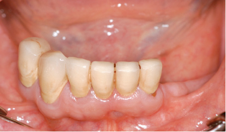
Fig 3-7a Residual teeth in the mandible.
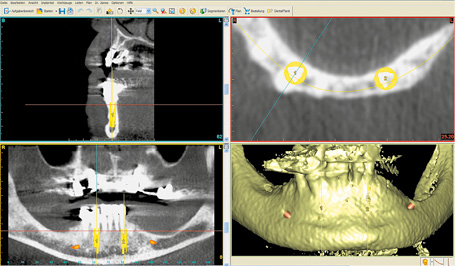
Fig 3-7b 3D analysis and planning.
Extraction and implant placement
An immediate complete prosthesis was fabricated for the patient before the extraction. It was decided not to make up an SOS template due to the immediate implant placement. Implant placement was to take place directly after the extraction with the Rescue Kit for the SOS (see page 137). The procedure took place under bilateral conduction and infiltration anesthesia. All the teeth were first extracted and a lingual as well as a labial flap created. The sharp edges of the sockets were leveled off and the whole residual ridge smoothed down to the same level (Fig 3-7c). The right implant was inserted first, into the septum between sockets 42 and 43 (Fig 3-7d). The drill guide for the 1.5-mm drill from the Rescue Kit was fitted onto the inserted implant (Figs 3-7e and 3-7f).
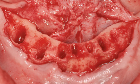
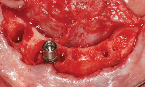
Fig 3-7d Insertion of the first implant into region 43.
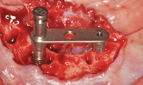
Fig 3-7e The drill guide has been screwed into place.
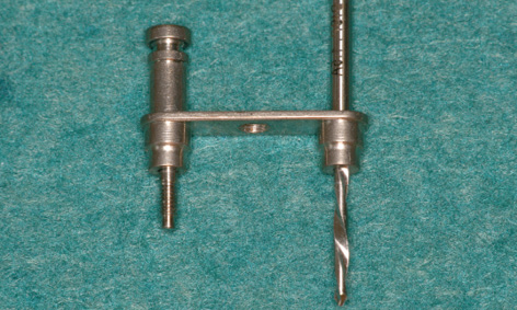
Fig 3-7f SOS Rescue Kit.
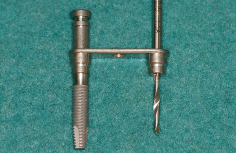
Fig 3-7g Drill guide fitted onto the implant.
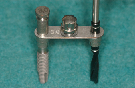
Fig 3-7h Additional pins used for stabilization of the drill guides.
Attention: The SOS Rescue Kit consists of the following components: double drill guide, with the 2-mm pin for the first 1.5-mm spiral bone drill, which can be screwed onto the implant (Figs 3-7f and 3-7g) and a sequence of screw-on pins for the subsequent drill guides from the set that are needed for preparation of the second implant bed (Fig 3-7h). The bar casing replica is also fitted onto the first implant, facilitating precise placement of the second implant (Fig 3-7i).
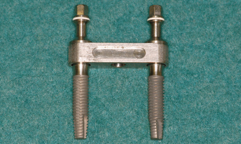
Fig 3-7i Bar casing replica for the insertion of the second implant.
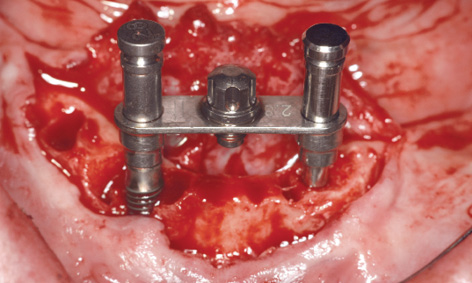
Fig 3-7j Preparation of the second implant bed.
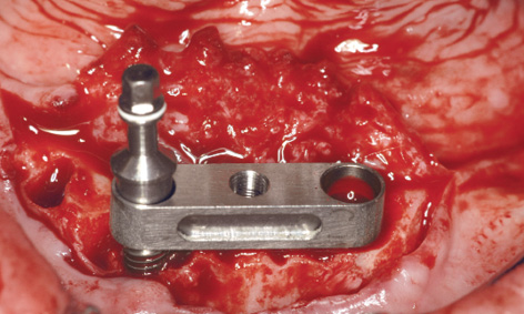
Fig 3-7k Bar casing replica fitted onto the first implant.
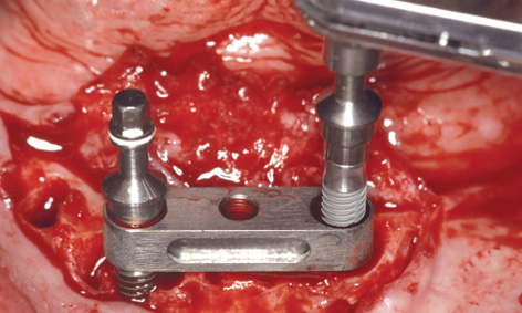
Fig 3-7l Insertion of the second implant.
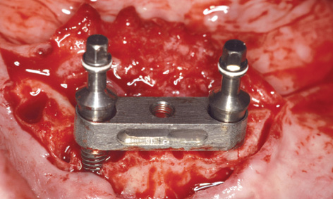
Fig 3-7m Fine-tuning the height of the two implants.
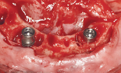
Fig 3-7n Implants in the final position.
This was followed by further drilling through the drill guides fitted onto the first implant; these bores were then checked with the vertical stabilization pins (Figs 3-7h and 3-7j). Following preparation of the second implant bed, the bar casing replica with the insertion post was fitted onto the first implant (Fig 3-7k). The second implant was inserted through the bar casing replica (Figs 3-7i and 3-7l). The casing replica also provides guidance regarding the depth to which the second implant needs to be inserted, to ensure that both implants are placed at the same level (Figs 3-7i and 3-7m). The insertion posts and replica were now removed (Fig 3-7n) allowing the bar to be fitted (Fig 3-7o). The bone chips harvested during the osteoplasty of the residual ridge and the preparation of the implant beds were used to augment the mandibular defects (Fig 3-7p). The augmentation was stabilized with a small Bio-Gide membrane (Geistlich) and tightly closed with sutures (Fig 3-7q). The prosthesis, reamed out in the anterior region, was tried in and used to take an impression of the new situation in the mouth (Fig 3-7r).
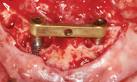
Fig 3-7o SOS bar fitted into place.
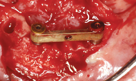
Fig 3-7p Augmentation of the bone defects.
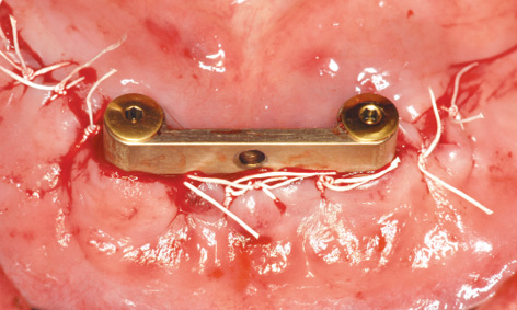
Fig 3-7q Suturing.
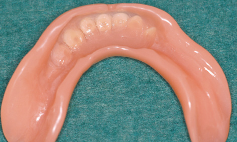
Fig 3-7r The prosthesis has been prepared for impression taking.
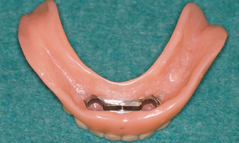
Fig 3-7s Definitive prosthesis.
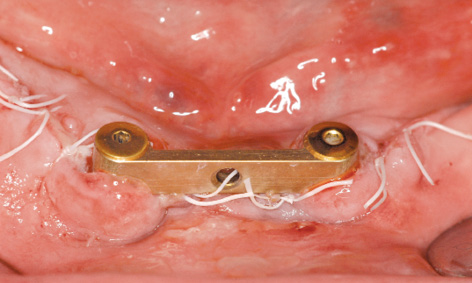
Fig 3-7t Clinical situation 1 day after implant placement.
Prosthetic loading
In the laboratory, the bar casing was incorporated into the denture, allowing the definitive prosthesis to be fitted (Fig 3-7s). While there was no further bleeding the day after implant placement, the entire operation area was swollen (Fig 3-7t). Before the prosthesis could be secured to the bar with the locking attachment, the patient had to bite down hard for a few minutes to displace the swollen tissue.
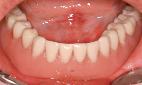
Fig 3-7u The prosthesis has been fitted.
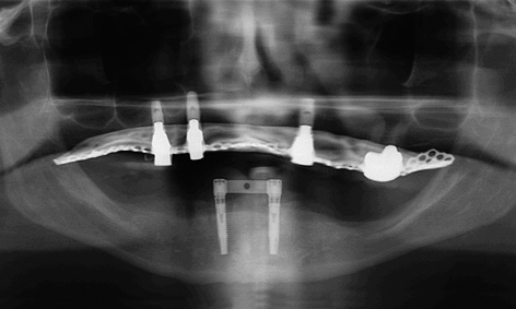
Fig 3-7v Follow-up panoramic radiograph.
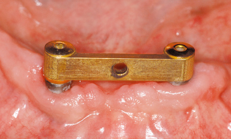
Fig 3-7w Labial view of the clinical situation after 6 months.
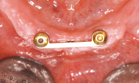
Fig 3-7x Lingual view.
The finished denture remained in situ for 2 days before being taken out, to give the patient some practice in handling it (ie, how to insert and remove it; see Fig 3-7u). The postoperative radiograph confirmed that the implants were securely anchored in the jaw (Fig 3-7v). Six months after implant placement, the clinical situation was satisfactory, although oral hygiene was not yet optimal. The patient was very satisfied. The soft tissue around implant 43 has degenerated slightly in the augmented region, favoring the formation of deposits (Fig 3-7w). The situation on the lingual side looks much better (Fig 3-7x).
Treatment course
- One-step treatment: extraction, osteoplasty, implant placement and augmentation, immediate loading (2012)
Treatment
|
Surgery and prosthetics: |
Dr Christoph T. Sliwowski, Dominika Sliwowska, DDS |
|
Dental technology: |
Dental Technician Ludger Jansen, DentaLab |
Problems and complications
Early loss of an SOS implant and re-implantation
Baseline situation
A 40-year-old woman, relatively young but with multiple morbidities, a heavy smoker (30 to 40 cigarettes a day), had been suffering from toothlessness for years (Fig 3-8a). She had lost her last teeth approximately 15 years previously. Since then, there had been repeated attempts to provide her with removable complete dentures, with no success. She could not manage the dentures and hardly ever wore them. Consequently, she had lost her last set when leaving her backpack on the bus 2 years previously. No new prosthesis had been fitted since then. To date, various dental practices, clinics and even university clinics had refused the patient implant treatment due to her high risk and poor financial situation. Clinically, both jaws have atrophied severely and the mandibular residual ridge appears to be very narrow (Fig 3-8b).
Diagnostic tools
- Clinical examination
- Panoramic radiograph
- CBCT with template
- SimPlant planning
- Surgical 3D SurgiGuide template
Treatment plan
1.Fabrication of the 3D template
2.Implant placement, direct definitive loading
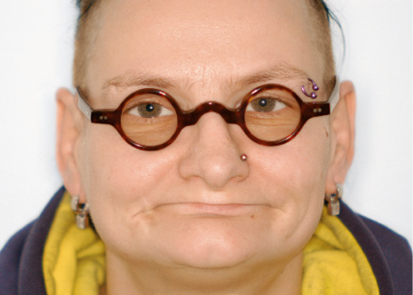
Fig 3-8a Relatively young edentulous patient before the treatment.
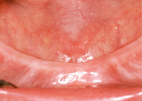
Fig 3-8b Narrow edentulous mandible.
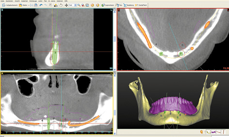
Fig 3-8c SimPlant planning of the SOS template.
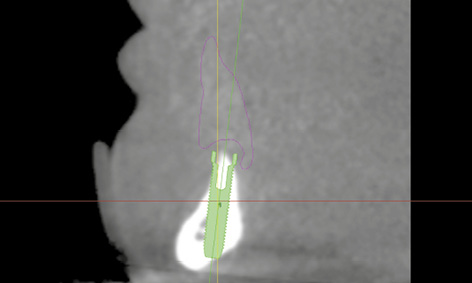
Fig 3-8d Positioning of implant 43 in the cross-sectional view.
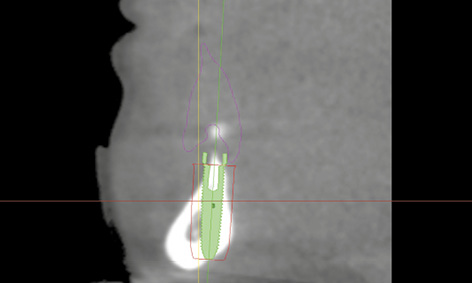
Fig 3-8e Positioning of implant 33 in the cross-sectional view. Thin lingual bone.
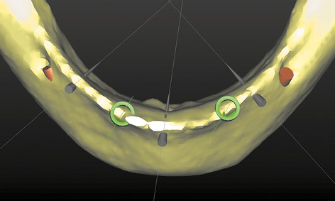
Fig 3-8f Occlusal view of the planning in the 3D reconstruction.
Fabrication of complete prostheses and 3D planning for the SOS SurgiGuide template
A new set of complete prostheses up to the wax-up stage was prepared first. During fabrication, eight glass beads were incorporated into the mandibular prosthesis to act as radiopaque markers. One CBCT scan was taken with this prosthesis in the mouth, and a second of the prosthesis alone. The double-scan function was used to combine the two scans, followed by the 3D planning (Fig 3-8c). Both nerves were marked in first and the implants and pins planned after that. The residual ridge was knife-edged, so that implant 43, aligned under the denture plate (pink outline) was partially exposed on both the labial and lingual side (Fig 3-8d). A similar situation was apparent with implant 33, and only the lingual bone layer was slightly thinner (Fig 3-8e). The sharp residual ridge and the positioning of the implants and stabilization pins can be seen in the occlusal view of the 3D reconstruction (Fig 3-8f). Despite the greater difficulty involved, the patient decided to have the implant treatment, and the SurgiGuide template was ordered from Dentsply.
Implant placement
The occlusal view of the residual ridge, even without flap reflection, confirmed the diagnosis based on the 3D reconstruction (Fig 3-8g). Before the start of the operation, the template was tried in the mouth and checked for stability (Fig 3-8h). During preparation, the template was removed and the stability of the vertical pins in the implant beds was checked (Fig 3-8i). Both implants were inserted with primary stability and the bar screwed into place (Fig 3-8j). After reshaping, the denture was fitted the same day. Over the next 2 months, the clinical situation appeared to be stable (Fig 3-8k). While the left implant in region 33 lies further lingually than planned, it was asymptomatic at the time (Fig 3-8l). At this point, the patient was satisfied with the treatment and enjoyed her “new,” securely fitting teeth (Fig 3-8m).
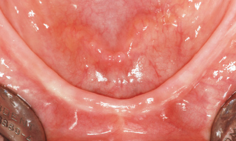
Fig 3-8g Occlusal view of the residual ridge.
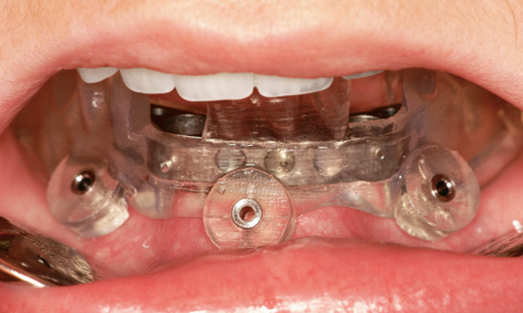
Fig 3-8h Try-in of the SurgiGuide template.
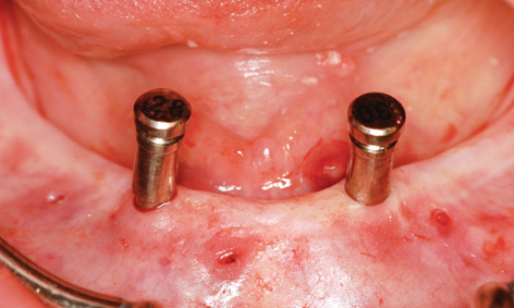
Fig 3-8i Checking the stability of the implant bed preparation.
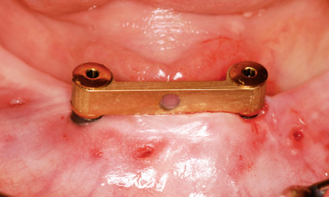
Fig 3-8j Fitted bar following implant placement.
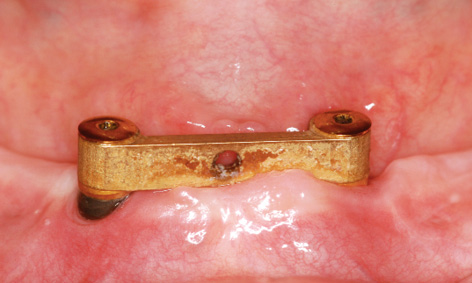
Fig 3-8k Fitted bar after 2 months.
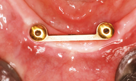
Fig 3-8l Occlusal view of the bar. Implant 33 lies too far lingually.
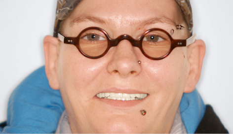
Fig 3-8m Happy patient with her “new” teeth.
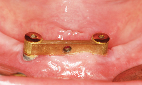
Fig 3-8n Clinical situation after 10 weeks.
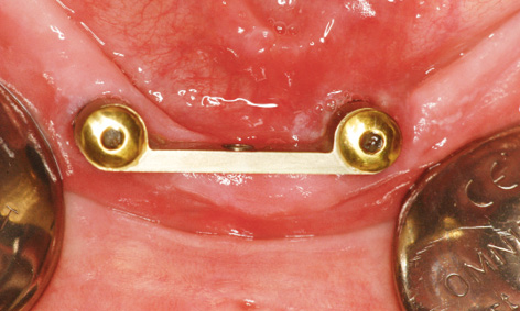
Fig 3-8o Peri-implantitis on the lingual side of implant 33.
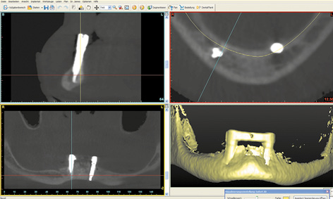
Fig 3-8p Follow-up CBCT scan.
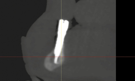
Fig 3-8q Implant 43 is anchored in the basal bone of the mandible.
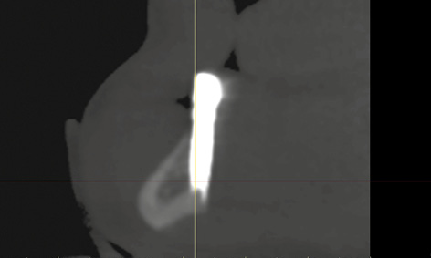
Fig 3-8r Implant 33 lies too far lingually.
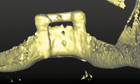
Fig 3-8s Lingual view of protruding implant 33.
Complication
After another 2 weeks, there was an unexpected change in the situation. The patient complained of pain around the left implant, although little had changed on the labial side at first glance (Fig 3-8n). However, an inflammatory reaction around implant 33 was diagnosed on the lingual side (Fig 3-8o). The inflammation was treated with H2O2 irrigation and photodynamic antimicrobial chemotherapy (PACT) 3 times a week. Since no improvement was apparent after 1 week, a CBCT scan was taken (Fig 3-8p). Implant 43 was securely anchored in the middle of the mandible (Fig 3-8q). Implant 33 appeared to have no bone cover on the lingual side (Fig 3-8r). In the lingual view of the 3D reconstruction, this implant appeared to protrude from the bone throughout its length (Fig 3-8s). To relieve the load on implant 33, the entire structure was removed and both implants were capped with cover screws (Fig 3-8t).
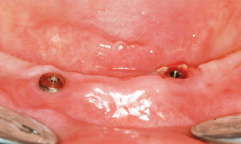
Fig 3-8t The bar has been removed and the cover screws fitted.
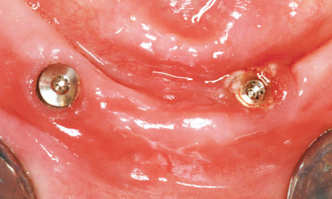
Fig 3-8u Peri-implantitis treatment around implant 33.
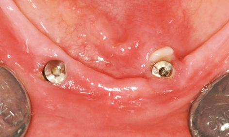
Fig 3-8v Minimal clinical improvement around implant 33, but with no pain relief.
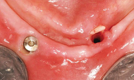
Fig 3-8w Explantation of implant 33.
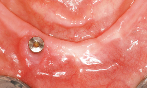
Fig 3-8x Healed residual ridge 3 months after the explantation.
Implant 33 was treated with H2O2 and PACT for another week (Fig 3-8u). Although a slight clinical improvement was apparent (Fig 3-8v), the patient insisted on removal of implant 33 due to the reportedly severe pain. Three months after insertion, implant 33 was unscrewed using a ratchet, with no difficulty apart from some initial resistance (Fig 3-8w).
Implant re-insertion
Following implant removal, the symptoms resolved and the residual ridge was left without a prosthetic restoration for another 3 months until it healed. The patient was able to do without prostheses for that time, since she had managed without them before. After 3 months, the residual ridge in the region of tooth 33 appeared to have healed (Fig 3-8x). However, an advanced dehiscence was identified around implant 43 on the labial side (Fig 3-8y). To re-insert the implants, the jaw was exposed with one incision over the ridge (Fig 3-8z). In the occlusal view, the residual ridge was still very narrow, and a slight retraction remained identifiable at the removal site (Fig 3-8aa). A drill guide was taken from the instrument set for precise preparation of the new implant bed in region 33. The abutment screw was 2-mm in diameter, allowing the 2-mm drill guide to be securely fitted onto the remaining implant (Fig 3-8bb). The first bore was prepared with the 2-mm spiral drill through the drill guide (Fig 3-8cc). The success of implant re-insertion depended on this first bore, as there could be no further perforation of the bone, particularly on the lingual side. After this drilling step, the preparation was closely checked using the 2-mm pin (Fig 3-8dd).
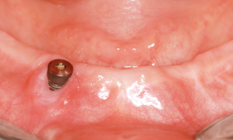
Fig 3-8y Mild peri-implantitis and dehiscence around implant 43.
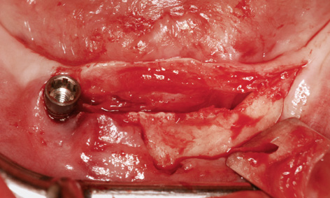
Fig 3-8z Crestal section over the residual ridge.
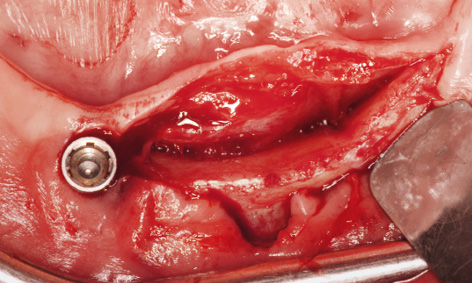
Fig 3-8aa Narrow residual ridge with lingual retraction in region 33.
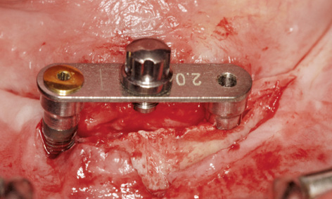
Fig 3-8bb 2-mm drill guide screwed onto implant 43.
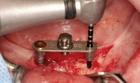
Fig 3-8cc Precise preparation with the 2-mm spiral drill.
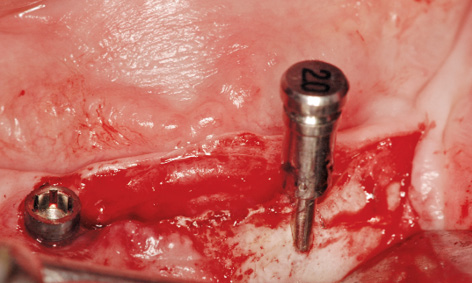
Fig 3-8dd Checking the preparation with the vertical 2-mm pin.
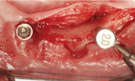
Fig 3-8ee Labiolingual positioning of the pin.
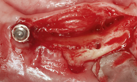
Fig 3-8ff Positioning the bore in the middle of the residual ridge.
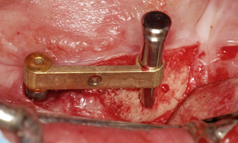
Fig 3-8gg Bar fitted onto implant 43 and continued preparation.
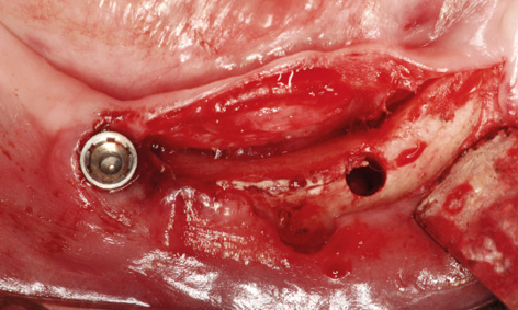
Fig 3-8hh Prepared implant bed.
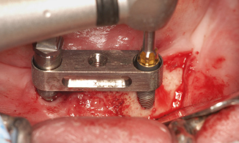
Fig 3-8ii Insertion of the implant through the bar casing replica fitted onto implant 43.
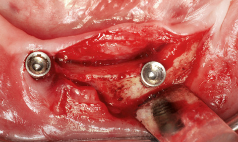
Fig 3-8jj Labiolingual positioning of implant 33.
The labiolingual position of the bore needed to be checked with particular care (Fig 3-8ee). The preparation now appeared to be at a sufficient distance from the lingual wall (Fig 3-8ff). The existing bar was screwed into place to increase the precision of the continued preparation with the 2.8-mm and 3.0-mm spiral bone drills (Fig 3-8gg). The implant bed was widened to 3 mm and appeared to be optimally positioned at the center of the jaw (Fig 3-8hh). A bar casing replica was fitted onto the existing implant 43 to enable insertion of a 3.5-wide and 17-mm long Neoss implant (Fig 3-8ii). Once inserted, implant 33 now appeared to have sufficient bone on the lingual side, greatly improving its long-term prognosis (Fig 3-8jj). Since both implants showed several exposed screw threads on the labial side, the bone also needed augmenting. For this purpose, implant 43 was exposed and the cortical bone perforated in several places for better revascularization (Fig 3-8kk).
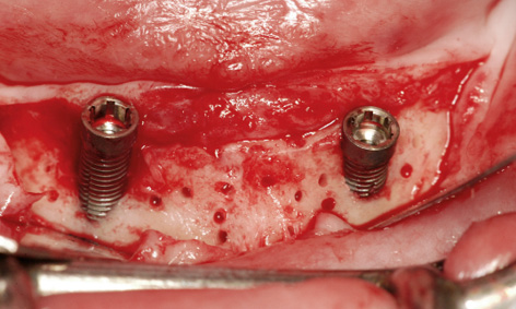
Fig 3-8kk Perforation of the cortical bone for the augmentation.
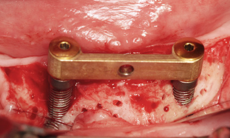
Fig 3-8ll The bar has been screwed into place.
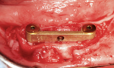
Fig 3-8mm Covering the augmentation material with Mucograft.
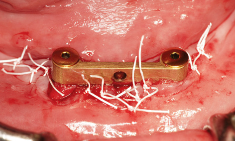
Fig 3-8nn Tension-free wound closure.
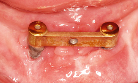
Fig 3-8oo Clinical situation after 10 months.
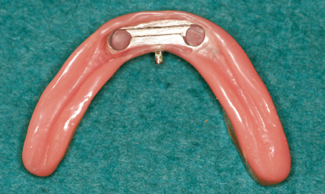
Fig 3-8pp Redesigned prosthesis.
The existing bar was then fitted onto the implants with the same abutments and the screws tightened with a 30 N/cm torque (Fig 3-8ll). The harvested bone chips were packed onto the jaw first, followed by human bone graft material (Puros, Zimmer Dental). Because of the dehiscence around implant 43 and the lack of attached gingiva on the labial side, the whole augmentation was covered with a Mucograft membrane (Geistlich), 20 × 30 mm in size (Fig 3-8 mm). The gingiva over the Mucograft membrane was adapted and secured with tension-free Gore-Tex sutures (W. L. Gore and Associates; Fig 3-8nn). The sutures were removed after 1 and 2 weeks. After another week, a new impression was taken with the old prosthesis and the bar casing was reincorporated into it (Fig 3-8pp). Despite the previous treatment failure, the clinical situation had largely stabilized, although the subsequent augmentation around implant 43 was of little benefit (Fig 3-8oo). The patient’s heavy smoking, illness and poor oral hygiene had probably contributed to the moderate outcome.
Treatment course
- Single-session procedure (2011)
- 3 months to removal
- 3 months to implant re-insertion
- 4 weeks to prosthetic loading
Treatment
|
Surgery and prosthetics: |
Dominika Sliwowska, DDS,Dr Christoph T. Sliwowski |
|
Dental technology: |
Dental Technician Ludger Jansen, DentaLab |
Stay updated, free dental videos. Join our Telegram channel
VIDEdental - Online dental courses


