Chapter 6
Diagnostic Medicine
Author’s Comment: Much has changed since I researched and wrote this chapter for the third edition of the book 12 years ago. At that time, it wasn’t known just how quickly the conversion from film to digital modalities in diagnostic imaging would occur; therefore, both film and digital were covered in the book. The reliability of the interface—called DICOM compatibility—between equipment by different manufacturers was a big issue. Today, of course, film cassettes, cassette pass boxes, darkrooms, and viewbox illuminators seem like ancient history, so total has been the shift to digital imaging. That doesn’t mean that private practice physicians here and there do not still have a film-based machine but, if they do, it is likely they are using a computed radiography (CR) reader or a digital radiography (DR) upgrade to convert the images to digital.
My goal was to present photos of equipment by all major vendors for each modality but, in the end, there were space limitations. I regret having to make some difficult choices, but with the ease of Internet access to vendor websites, the full panoply of choices is available. In previous editions of this book, typical equipment room layouts were presented for MRI, CT, and nuclear medicine. Fortunately, these planning guides are now readily available with open access on most vendor websites.
DIAGNOSTIC IMAGING
Today, there is seamless transfer of images throughout the enterprise—total connectivity among physicians, radiologists, and hospitals. Referring physicians and specialists who previously had to wait many hours to several days for a film to be retrieved and delivered now have instant access to patient information: no misplaced or lost films, no need to carry films from one location to another, elimination of X-ray retakes (exposing the patient to more radiation) to compensate for errors in technique, and elimination of the cost of film. Instead, digital images go directly to a picture archiving communication system (PACS) where they can be reviewed, distributed, and ultimately, stored on a secure network. GE’s Centricity™ is an example of a PACS data management system (Figure 6-1). Several manufacturers offer PACS, such as Philips, Sectra, and Novarad, each having distinctive proprietary features to give them a marketing advantage.
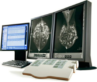
Figure 6-1. Advantage PACS workstation.
Goal: Acquiring Better Diagnostic Information in Less Time and with a Lower Dose
The new diagnostic imaging equipment showcased at the Radiological Society of North America (RSNA) exhibit each November is often stunning in its innovation. For those who may not be familiar with it, RSNA is “Mecca” for anyone associated with any aspect of diagnostic imaging. Held each November or December at McCormick Place in Chicago, it attracts over 65,000 attendees worldwide. Online magazines like Diagnostic Imaging, Medical Imaging, and AuntMinnie.com publish a preview issue prior to the event and a new product review afterward, both of which are very informative.
A review of trends from the 2012 RSNA reveals a focus on low-dose radiation solutions for CT (Toshiba Aquilion RXL, Hitachi Scenaria 128-slice) and mammography (Siemens’ Mammomat Inspiration Prime Edition) by several vendors, reduction in size of mobile devices, more compact design of devices that are already portable, such as a mobile X-ray unit, and numerous enhancements of ultrasound. In addition, MRI machines that eliminate acoustic noise during 3D image acquisition and reconstruction were shown but are pending approval for sale in the U.S. market. Many other innovative products were on display for use in acute care settings and academic medical centers such as interventional radiology and surgical suites incorporating MRI, but these are outside the scope of this book.
Following is a glimpse at specific modality innovations:
- Ultrasound elastography imaging—measures of tissue stiffness may be able to show if breast tissue is benign or malignant. The benefit is to reduce breast biopsies.
- Portable ultrasound (Siemens’ Acuson Freestyle) with the first wireless transducer to enhance infection control because it is fully immersible in liquid for disinfection.
- Ultrasound by Philips (iU22 xMatrix) offers 2D and 3D images and has an enhanced transducer capable of advanced scanning to see vascular plaque, details of dense breast tissue, and for fetal heart navigation and more. A built-in database of anatomical structural models and intelligence tools simplify exams.
- The Philips combination PET/MRI (Ingenuity TF PET/MR) scanner combines molecular data and MR with integrated software. This is especially useful in neurology, oncology, and cardiology cases.
- The Carestream DRX-Revolution is a mobile X-ray system with a collapsible column, badge-swipe login, wireless digital detector, and an in-cart battery charger, all in a compact unit that is easier to maneuver than most C-arms.
- Various workflow solutions were introduced for diagnostic workstations, making it easier for radiologists to view, annotate, and manipulate images and send them to referring physicians (optimized image distribution).
- The Philips IntelliSpace Portal enables thin-client computing solutions for advanced image review with the flexibility to diagnose from any location that has broadband access.
PACS
Picture archiving communication systems manage digital data and images. Each vendor offers somewhat different system design, user-friendly interface, and certain proprietary features. PACS is a generic term for these data acquisition and image management systems, which generally have the following four components: image acquisition, image storage, image transfer (over a network), and image retrieval. PACS refers, in a generic sense, to any electronic substitute for film, but PACS can be based on direct ray (DR) transfer of images or computerized radiography (CR), which is explained below. (Note that “DR,” as a term, is interchangeably used to refer to direct ray, digital radiography, and direct radiography.) PACS may further be defined as:
- Mini-PACS—connecting single or multiple imaging modalities using viewing stations with or without soft reading and/or digital storage archiving.
- Full PACS—connecting all modalities, viewing/reading soft copy/enlarged digital storage. It is integrated with both the hospital and the radiology information systems and distributes data and images throughout the healthcare network.
- Teleradiology—connecting the radiology service to the radiologist’s home, emergency department, intensive-care unit, or rural clinics.
Computed Radiography
Computed radiography (CR) is an older radiography technology that uses electronic media instead of film. It is used to retrofit analog machines to digital output but requires both a hardware and software upgrade. The film receptor has to be changed to a digital CR receptor. The cassettes typically look like standard film cassettes, but they don’t have film in them; they have a phosphor plate that records the image and gets reused. The tech takes the plate out of the unit and puts it into the cassette holder to take the exposure then puts it into a plate reader, which reads the image and simultaneously erases the plate for reuse. This has several additional workflow steps associated with it compared with a more direct method of recording the image. The image that has been read is stored on an internal hard drive, which can then send the image to a PACS or print it on paper or film. The plates are heavy and expose technologists to back injuries so it is not ideal from an ergonomic or efficiency/throughput standpoint.
Direct Radiography
Direct radiography (DR) bypasses the phosphor plate; it is a direct transfer of the image to a PACS. One can do many more procedures per room because the tech has fewer workflow steps. Flat panel detector plates, 14 × 17 inches, fit into standard bucky trays and holders. The Fujifilm FDR D-EVO system includes detector plates, an FDX console, a control box, and a power supply. Synchronization of the detector activation requires connection to the existing X-ray generator system.
Converting Film to Digital Images
There are several ways of transitioning from film to a digital system. The major radiographic equipment manufacturers have recognized the need for a transitional strategy to help make this conversion by developing systems that achieve filmless imaging in phases, over a period of time, working with existing diagnostic equipment.
In addition, film can be converted to digital images by digitizing the X-ray whereas images from modalities that cannot output digitally can be converted into digital images by video capture systems (multi-frequency video capture boards installed in PC controllers equipped with barcode readers to facilitate quick entry of patient details and identification data).
DICOM Compatibility
All manufacturers are currently making products that are DICOM compatible, which facilitates interconnectivity among pieces of equipment purchased from different vendors and ensures that all images will reach the server without degradation or loss. Digital Imaging and Communications in Medicine (DICOM) is the standard for compliance developed by the American College of Radiology and the National Electrical Manufacturers Association. DICOM provides a format for how files are created to make it possible to move information from one system to another. The goal is total interface among the equipment of various manufacturers.
Image Storage
It is a challenge to keep pace with the vast amounts of graphical data (radiographic images) and the need for short-term and long-term storage, as well as quick retrieval of old files to compare with new imaging studies for a specific patient. There has been an exponential increase in the amount of data produced. Common is a three-tier storage strategy described as Online, Nearline, and Offline, that refers to the immediacy of access to data. Data may be stored in a main server with storage capacity enhanced by redundant arrays of inexpensive disks (RAID), which provides immediate-access “online” data. Online storage of images—perhaps six months of studies—would be on the RAID (although it is possible to configure a RAID-centric PACS model to accommodate more than a year’s studies available online). From there, they will likely go to nearline storage, which may constitute a 6- to 12-month period, and this storage may be on an ultra-high-capacity magnetic tape and optical “jukebox.” After that, images would go to offline storage for long-term archiving on magnetic tapes and optical discs. Realizing the size of these graphical files, which must handle large images, the demand for large memory configurations and vast storage capacity is staggering. To be able to store and retrieve such large amounts of data in a matter of seconds requires high-speed, broadband networks and high-resolution displays.
A rack located in a secure IT room can hold the uninterrupted power source (UPS), RAID, server, and long-term archive library. (Rorke Data is a leading manufacturer of mass storage units.) Multiple archival libraries can be connected. Images move from online (the server) to nearline (the jukebox or archival library), and then offline, which may be in a remote location or even cloud-based. Redundancies are built into all of these archiving systems to account for power failures, loss of data, fire, and so forth. Some PACS are designed to automatically route data, at certain pre-established intervals, to three to five redundant storage locations. Of course, the cost of storage media is a large contributor to total costs. Optical storage, also known as MOD, Magneto Optical Storage, is a disk read by laser and considered the most reliable for long-term storage.
Jukeboxes or archive libraries must be placed in a secure, restricted-access IT room, which may be within the facility or located remotely. The storage “racks” often have internal cooling fans, but good air circulation and constant temperature (cool) is important. Some are accessed only from the front, others from the rear, but none should be placed too close to a wall as there is considerable cabling and one must have access to it for maintenance. Once a library archive or jukebox is operational, it cannot easily be moved.
For hybrid suites, there will still be a need for conventional film filing. As conversion to digital occurs, there is often a need to store film files for a period of time. For a fully digital operation, film filing is replaced by a room for the server and archives (jukebox) although, theoretically, the jukeboxes (and even the server) may be at a remote location. Film files used to require a tremendous commitment of space, whereas now perhaps a room 8 × 10 feet may store 10 years of data.
Application Service Provider
PACS can be outsourced to an application service provider (ASP). This represents a way of financing the endeavor, which, much like lease payments, comes out of an operating budget rather than capital investment. And, much as with a lease, as equipment becomes obsolete it is replaced because the equipment is owned by the ASP. This option is often priced on a per-patient (procedure) basis.
ASPs grew out of the recognition that financing the conversion to digital imaging out of capital budgets constituted a big hurdle for many organizations. There is great variety in what ASPs offer. Basically, they buy software and hardware from a variety of vendors and customize a system to meet an individual enterprise’s needs. Some of these are proprietary models that use Web-based architecture to enable a number of data and image management tasks to be executed: scheduling and registering patients, processing and interpreting diagnostic studies, archiving images, and distributing these data to referring physicians.
Getting from Here to There
The challenge in writing this chapter is that it needs to reflect the hybrid nature of what designers will encounter whether designing a one-room radiology suite for an orthopedist or general practitioner or a diagnostic radiology suite in a medical office building. The focus of the discussion, and the market for this book, is the non-hospital-based facility, which, in this case, means a radiology suite that serves tenants in a medical office building or that may be freestanding. An exception to this is the plan in Figure 6-21, which is hospital-based but also serves ambulatory patients. It is included because it exhibits good planning concepts that are relevant to an MOB setting as well. As previously stated, the editorial assumption is that film is gone (except possibly for the need by a physician practice to physically store aged films for a period of time) and that any film-based machine will have a software upgrade to enable it to communicate with a CR plate reader or DR and thereby result in digital output.
Principles of Radiography
General principles are commonly understood. A limb is exposed to X-rays, which penetrate body tissues, and produce a 2D image. Since body tissues absorb different amounts of radiation, bones, fat, gas, and so on make different exposures compared with surrounding tissues, which allows the observation of internal organs and structural anatomy without pain and with small exposures to radiation.
In addition to examination of limbs, diagnostic imaging is used to diagnose the presence of gallstones and kidney stones, tuberculosis, arthritis, and bone tumors; to discover foreign bodies in soft tissue; to detect enlarged or malfunctioning glands; to scan the brain; to reduce tumors (radiation oncology); to monitor a child in the womb (ultrasound); and to diagnose scores of other diseases. Some forms of diagnostic imaging, such as ultrasound, do not involve radiation.
Making an X-ray film of a leg or the chest requires no special preparation, but filming organs such as the gallbladder or the gastrointestinal tract requires that the patient fast before the procedure and then drink a special liquid or receive an injection that makes the organs visible to the radiologist. Since the designer must understand these procedures in order to plan an efficient suite, a brief outline of diagnostic radiology modalities follows.
Diagnostic Imaging Modalities
Fluoroscopy
Fluoroscopy enables the radiologist to watch internal organs at work. Gastrointestinal studies are common. The patient swallows or receives an injection of a contrast medium—air, barium sulfate, or organic iodine compounds—which causes the soft-tissue systems of the body to be outlined. X-rays passed through the body strike the input phosphor of an image intensifier tube, and that image is intensified electronically and can be viewed on a video monitor. (Monitors may be ceiling or wall mounted, or portable, on the floor.) With a video camera, screen images can be converted into real-time studies for future reference.
A contrast medium injected into a blood vessel (angiography) travels with the blood supply to a specific organ and allows the radiologist to examine that organ. For a study of the large intestine, a patient is given a barium enema. The radiologist makes sequential spot film (or digital) radiographs while the barium travels through the large intestine. To study the digestive system, a patient drinks barium and the radiologist films it traveling down the esophagus into the stomach, following it through the small intestine. Of course, endoscopy has greatly reduced the number of gastrointestinal barium studies.
Digital fluoroscopy is the technique for converting X-rays into visible images without film. Photographic film is replaced by an electronic image tube that produces a direct image of a broken bone, lung, brain, or other body organ being studied. This eliminates photographic processing. The Siemens Luminos dRF is a 2-in-1 radiography and fluoroscopy system with Human Touch Technology: one touch and the machine moves where it is needed (Figure 6-2). The table drops down to the height of a standard chair for ease of access. Fluoroscopy rooms require a high ceiling because the tables tilt (Figure 6-3).
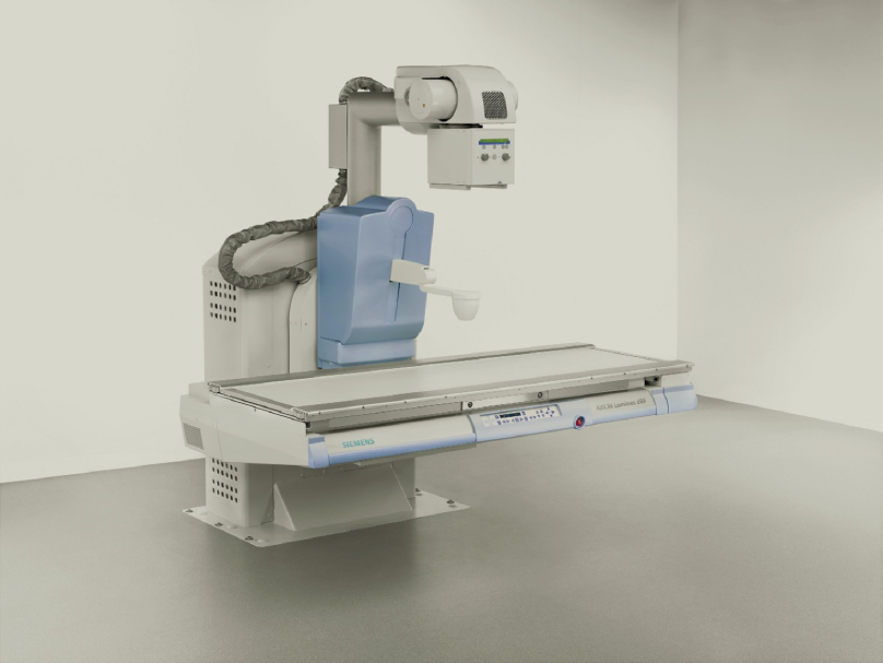
Figure 6-2. Digital radiography and fluoroscopy. AXIOM Luminos dRF with Human Touch Technology.
Figure 6-3. Radiography and fluoro machine with table in tilted position. Precision 500D∗.
Ultrasound
Ultrasound does not involve radiation. A high-frequency sound, much like sonar, bounces off internal body structures. Ultrasound is particularly useful in examining soft pelvic tissue masses, gallbladders, or a fetus in the womb—procedures where even low doses of radiation might be dangerous. Ultrasound is also commonly used to image the heart (echocardiography) and for studies of blood flow in arteries and blood vessels. It is commonly used to analyze suspicious breast lesions, and tissue can also be biopsied using ultrasound. Physicians who do in-vitro fertilization use ultrasound routinely during a variety of procedures. Ultrasound machines can be found in Chapter 5 (see Figure 5-7) and in Chapter 3 (see Figures 3-79, 3-80, and 3-84).
Nuclear Medicine
Nuclear medicine deals with the diagnosis and treatment of disease with radioactive isotopes—chemicals that are unstable and break down, giving off radioactivity. The isotope may be given to the patient orally or by intravenous injection. The substance is specific to a particular gland or organ (e.g., iodine travels to the thyroid gland). The amount of the isotope absorbed by the gland permits the radiologist to determine the function of the organ and to trace its outline. Nuclear scans are useful for diagnosing brain tumors and malfunctioning of the kidneys, pancreas, and thyroid. Positron emission tomography (PET) scanners are considered one of the best modalities for detecting cancer lesions. A combination CT/PET scanner (Figure 6-4) represents a fusion of CT’s ability to render anatomy with PET’s imaging of critical metabolic processes.
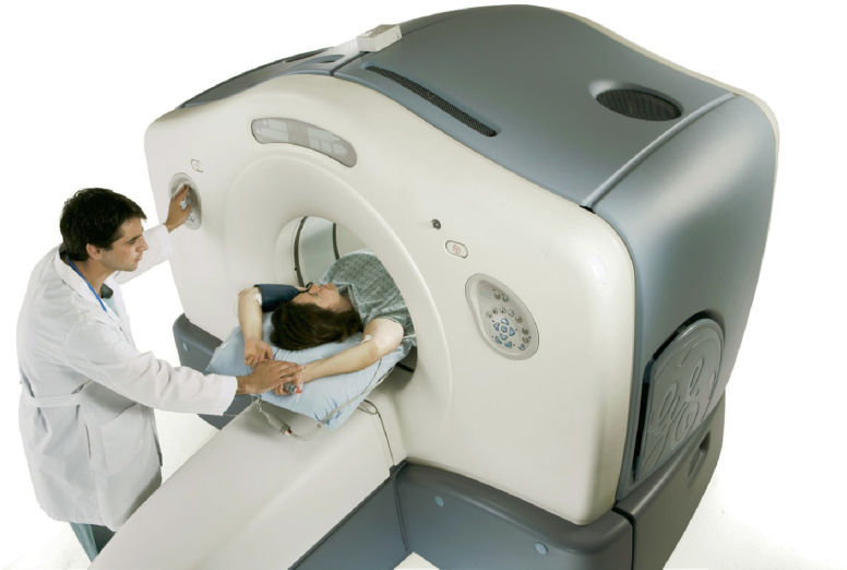
Figure 6-4. Discovery∗ PET-CT scanner.
Computed Tomography
Computed tomography (CT) allows physicians to see cross sections of internal body structures, enabling the radiologist to discover tumors embedded in soft tissue or organs that formerly could not be seen by radiographic procedures. Thus, CT scans have eliminated much exploratory surgery and offer the patient greater safety by reducing the need for more dangerous, often painful, tests.
The patient lies on a table that slides through a rotating doughnut-like enclosure called the gantry (Figures 6-5 and 6-6). X-rays scan narrow cross sections of the body in a painless, noninvasive procedure. For example, 180 scans just 1 degree apart may be taken of an area. The numerous images are collected by a detector and reconstructed by a computer into a composite scan of the organ or tissue. CT scanners represented a major breakthrough in diagnostic imaging technology when they were introduced in 1977 and the technology has continued to advance with the current focus on lower levels of radiation and better image acquisition. During the scan, 3D images are built in real time and are completely constructed by the time the scan ends.
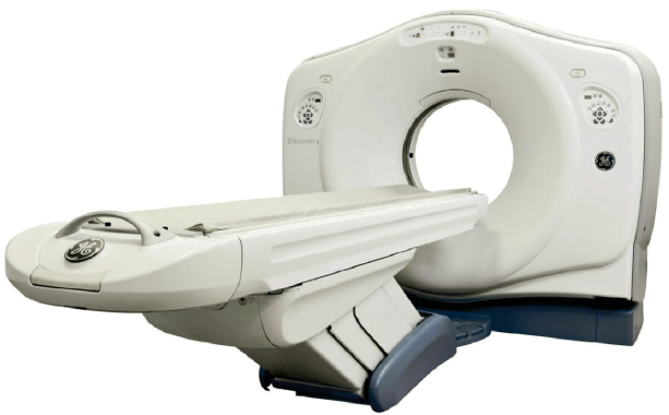
Figure 6-5. Computerized tomography, Discovery∗ CT750.
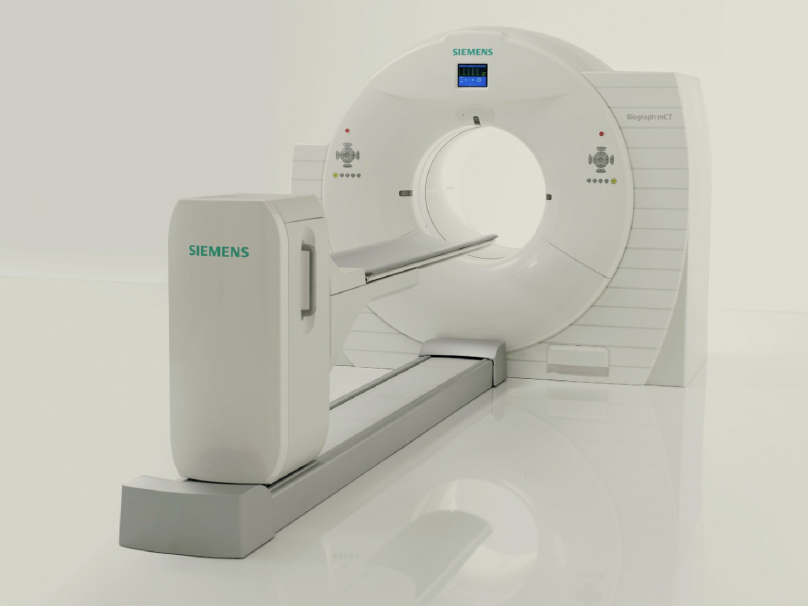
Figure 6-6. Computerized tomography Siemens Biograph™ TruePoint™ PET CT.
Mammography
Low-dose mammography, an X-ray of the breast, is considered to be the most accurate and safe means of detecting breast cancer at an early, usually curable stage. According to the American Cancer Society, one in three women in the United States will get breast cancer at some point in her life. Therefore, screening mammograms are recommended on a regular basis for women over the age of 40 and perhaps even earlier for those who have a family history of breast cancer. Refer to Figures 5-25 and 5-26 for mammography machines.
Radiation Oncology
Through use of a linear accelerator, tumors are bombarded by very narrowly focused, high doses of radiation in an attempt to kill cancer cells. The course of treatment is carefully plotted and monitored by a radiation physicist and the radiology team. The normal course of treatment runs six weeks, during which time the patient typically reports five times per week. Both facilities in Color Plate 18, Figures 6-7 and 6-8 offer patients calming views of nature and an aesthetically appealing environment.
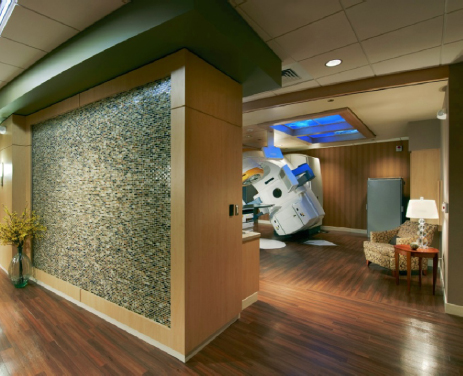
Figure 6-7. Radiation oncology linear accelerator with water feature wall at entry.
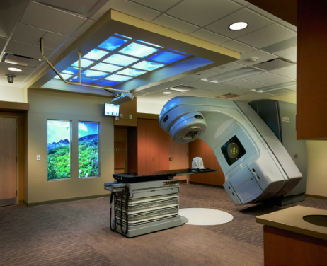
Figure 6-8. Radiation oncology linear accelerator with backlit images of nature in wall and ceiling.
Magnetic Resonance Imaging
Magnetic resonance imaging (MRI) has been heralded as a major innovation in diagnostic imaging and, today, it represents 20 percent of the medical imaging market. It provides exceptional soft-tissue contrast and is especially good for imaging the central nervous system and, in particular, the brain. It permits early and accurate diagnosis of a wide variety of conditions, including brain tumors, strokes, hemorrhage, and multiple sclerosis. Spinal cord compression is more effectively shown by MRI than by other imaging techniques. A pinched nerve or the effects of arthritis can be graphically demonstrated and may prevent the need for a myelogram or CT study. MRI is also effective for diagnosing knee injuries and cancers of the musculoskeletal system.
MRI does not use X-rays, but depends instead on the interaction of radio waves and small particles within the body, called protons, in the presence of a strong magnetic field generated by the MRI equipment. A simplified explanation of a very complex process follows.
Inside the body, protons absorb energy from incoming radio waves of various frequencies and, in turn, give off energy in the form of radio waves. These outgoing signals are recorded by a highly sophisticated computer and reconstructed into an image similar to that produced by CT, but generally with higher resolution, showing more detail and an enhanced view of diseased tissues.
Advantages to the patient are that no special preparations are required before the procedure, no injections of contrast media are generally required, and it does not use radiation. Currently MRI examinations are expensive and take longer than a similar CT procedure. Other applications of MRI include in vivo spectroscopy and study of living tissues, providing information on processes occurring inside the cell. A single example of the derived benefit of this is diagnosing a tumor without resorting to biopsy, based on the fact that tumors are known to affect cell metabolism. There are many applications of MRI continually in development. The MRI by Toshiba in Color Plate 19, Figure 6-10 offers patients a “spa” theme and is one of the quietest machines available. The facility in Color Plate 19, Figure 6-9 connects patients to nature with a luminous sky and treetops spreading across the length of the room.
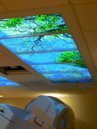
Figure 6-9. Linear accelerator with luminous ceiling providing a positive distraction for patients.
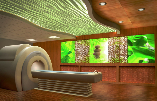
Figure 6-10. Toshiba MRI with spa design features.
Planning Considerations
The purpose of this chapter is to introduce the reader to the most common diagnostic imaging modalities and to explain the general parameters of designing rooms to accommodate this equipment. Clearly, one could write an entire chapter on each of the modalities if one wanted to cover thoroughly all aspects of design and construction. The focus of this discussion is the outpatient radiology facility that would commonly be found in a medical office building, as opposed to one located within a hospital. Refer to Table 6-1 for a space program.
Table 6-1. Analysis of Program Diagnostic Imaging
| No. of Radiologists On site | 1–2 | 2–3 | ||
|---|---|---|---|---|
| Waiting Room | 16 × 24 = 384 | 18 × 24 = 432 | ||
| Business Office | 14 × 18 = 252 | 16 × 20 = 320 | ||
| Dressing Room | 6 @ | 4 × 4 = 96 | 10 @ | 4 × 4 = 160 |
| Handicapped | 6 × 8 = 48 | 2 @ | 6 × 8 = 96 | |
| General Radiography | 16 × 20 = 320 | 16 × 20 = 320 | ||
| Radiography/Fluoroscopy | 16 × 20 = 320 | 2 @ | 16 × 20 = 640 | |
| Toilet | 8 × 8 = 64 | 2 @ | 8 × 8 = 128 | |
| Ultrasound | 2 @ | 10 × 12 = 240 | 2 @ | 10 × 12 = 240 |
| Toilet | 8 × 8 = 64 | 8 × 8 = 64 | ||
| Nuclear Medicine | — | — | ||
| Hot Lab | — | 8 × 8 = 64 | ||
| Procedure Room | — | 16 × 20 = 320 | ||
| Patient Prep | — | 10 × 10 = 100 | ||
| Subwaiting | — | 10 × 12 = 120 | ||
| Toilet | — | 8 × 8 = 64 | ||
| CT Scanner Suitea | 16 × 29 = 464 | 16 × 29 = 464 | ||
| MRI Suiteb | — | 23 × 51 = 1173 | ||
| Toilets | 3 @ | 8 × 8 = 192 | 4 @ | 8 × 8 = 256 |
| Tech Work Area | Varies 120 | Varies 150 | ||
| Private Office (Radiologist) | 2 @ | 10 × 12 = 240 | 3 @ | 10 × 12 = 360 |
| Administrator | 10 × 12 = 120 | 10 × 12 = 120 | ||
| Radiologists’ Reading Room | 12 × 12 = 144 | 12 × 16 = 192 | ||
| Storage | 8 × 10 = 80 | 10 × 12 = 120 | ||
| Staff Lounge | 12 × 16 = 192 | 14 × 16 = 224 | ||
| Breast Center | — | |||
| Waiting Area | 14 × 18 = 252 | |||
| Toilets | 2 @ | 8 × 8 = 128 | ||
| Dressing Room | 8 @ | 4 × 4 = 384 | ||
| Handicapped Dressing Rm. | 2 @ | 6 × 8 = 96 | ||
| Mammography | 3 @ | 10 × 12 = 360 | ||
| Stereotactic Room | 16 × 18 = 288 | |||
| Tomosynthesis | 10 × 12 = 120 | |||
| Breast-Specific Gamma Imaging (BSGI) | 12 × 12 = 144 | |||
| Ultrasound | 10 × 12 = 120 | |||
| Toilet | 8 × 8 = 64 | |||
| Radiologist’s Reading Room | 10 × 10 = 100 | |||
| Consultation | 10 × 10 = 100 | |||
| DEXA | 10 × 14 = 140 | |||
| Tel. Equip Room | 4 × 5 = 20 | 4 × 5 = 20 | ||
| Server /IT Closet/PACS | 6× 8 = 48 | 6 × 8 = 48 | ||
| Janitor’s Closet | 4 × 4 = 16 | 4 × 4 = 16 | ||
| Biohazard Storage | 5 × 6 = 30 | 5 × 6 = 30 | ||
| Subtotal | 3,474 SF | 8,513 SF | ||
| 25% Circulation | 868 | 2,128 | ||
| Total | 4,342 SF | 10,641 SF | ||
| aIncludes procedure room and control room. | ||||
| bIncludes procedure room, control, and electronic equipment room; layouts and room sizes vary per manufacturer and model/type of magnet. | ||||
| Note: The above sizes are an approximation, since radiography rooms must also have control areas, which may be inside or outside the room. Many radiologists will have both a private office and a reading room, while others may share a private office. There are many variables, depending on whether the radiologists rotate among several locations or remain at one. Tech work areas will also vary, whether it is a room or a workstation within a staff-only hallway running along one side of procedure rooms. | ||||
Before a space planner can begin to plan the suite, a program must be developed. There is a difference in how this is accomplished when the client is an independent radiology group developing a tenant space in an MOB (see Figure 6-19) versus a client that represents a radiology department that will serve a 250,000-square-foot ambulatory care center affiliated with a hospital (see Figure 6-14). In the former case, the radiology group will generally detail for the space planner the number and type of diagnostic imaging rooms that will comprise the suite. There is no way a space planner can second-guess this, as it depends on a number of considerations. First, if the radiology group has CT at another office not too far away, it’s unlikely they will duplicate this equipment. Second, the number of physician tenants in the building and their respective specialties will influence the type of equipment the radiologists buy. Third, the medical building’s proximity to a hospital and the type of imaging modalities available at the hospital may influence the selection of equipment for the facility, especially if the same radiology group staffs the department at the hospital.
In the other example (the radiology department serving a large ambulatory center), the programming will be done by the architect or planner, who will do workload analysis to determine the number and types of procedure rooms required. This must be done in collaboration with the radiologists because throughput (volume on each imaging modality) will be influenced by decisions to purchase new equipment and the extent of overall digital integration in the enterprise. If the medical center with which the ambulatory facility is affiliated has a high-profile cardiology, oncology, or neurosciences center, a high enough volume of patients in one of these areas may warrant the purchase of specialized imaging equipment. All of these issues must be considered and factored into the workload analysis and ultimate program that is developed.
These are the six basic planning considerations:
- Equipment
- Patient flow
- Staff flow
- Information flow
- Function
- Flexibility
Equipment
A number of manufacturers offer equipment for each imaging modality. Room size and critical dimensions vary considerably, as do utility requirements. There are numerous accessory or ancillary items that may be added to each major piece of equipment. The space planner, therefore, may be faced with a number of possible combinations of equipment for an individual room. The radiologist will make these selections, but the space planner must obtain from each manufacturer a planning guide and specifications for each unit. Fortunately, this type of information is available online at each vendor’s website (see Figure 6-37). Clearly, equipment dictates the size of each room, with function and future requirements being the two important considerations. Manufacturers usually offer planning services to plan a department and often produce almost a full set of construction documents. One must remember, however, that their goal is to sell equipment and to make sure it fits in the room. These services should be relied on only to provide technical assistance to the space planner or architect, who is much more likely to produce a functional layout that considers overall patient flow, business office activities, and the relationship of each room to the whole.
When equipment is placed in the room, function is achieved when proper clearances are preserved for items that swivel, extend, or tilt and for travel of the tabletop. Other aspects of function are patient access and staff ability to move around the room (e.g., if a patient needs to be transferred from a stretcher or gurney alongside the X-ray tabletop). Finally, each procedure room must have an area within it, or outside of it, for controls. Within the room, the control area is a lead-lined partition with a window in it. The tech stands behind it to operate the generator that controls the equipment in a film-based set-up. Note that the window must have a minimum 18 inches of wall on the leading or open end to protect the tech. The control unit is not very large for a standard digital radiography machine. It will have a stand-up (see Figure 3-72) or sit-down-height countertop approximately 4 feet wide for the operator’s control console in addition to a quality-control computer. Figure 6-11 shows a control workstation for a PET/CT and Figure 6-12 shows one for an MRI.
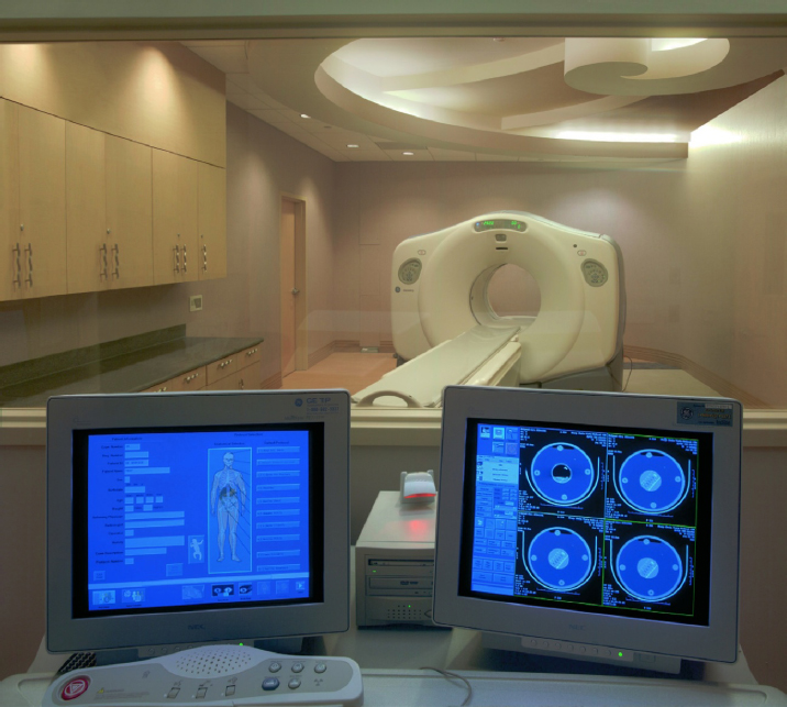
Figure 6-11. Operator’s console looking into PET/CT room with chambered nautilus shell ceiling design.
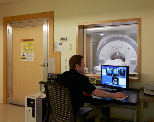
Figure 6-12. MRI control area.
It is optimal, when designing major radiography or radiography/fluoroscopy rooms (abbreviated R&F or R/F), to size them generously in order to accommodate future technology and anticipation of more interventional procedures requiring more staff. Radiographic rooms are very expensive to remodel due to lead shielding and other construction features.
Patient Flow
The overall layout of the radiology suite is driven by a desire to separate patient circulation from the staff work area (Figure 6-13). In Figure 6-14, patient dressing rooms are toward the front of the suite but also near procedure rooms. In the Breast Center (see Figures 5-12 and 5-13), patient circulation is on one side of the procedure rooms, while staff enter from a work corridor on the other side of those rooms. In Figure 6-21, a tech work core provides staff access to four exam rooms while patients enter from a different door. In Figure 6-15, a tech work area provides staff access to three exam rooms, with patients entering from a dressing and subwaiting area. However, it is not always possible to do this (Figure 6-16).
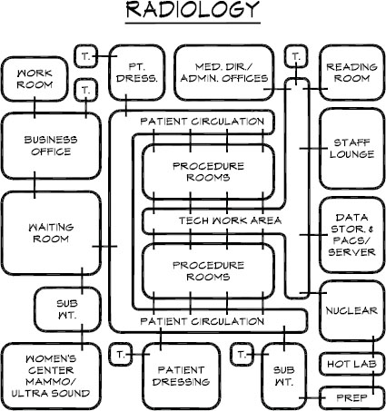
Figure 6-13. Schematic diagram of radiology suite.
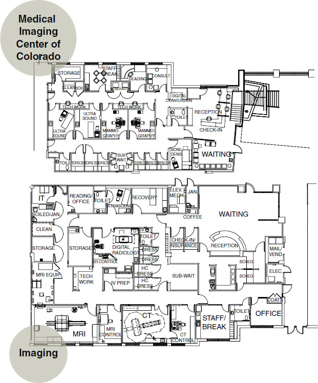
Figure 6-14. Space plan of diagnostic imaging, including breast center.
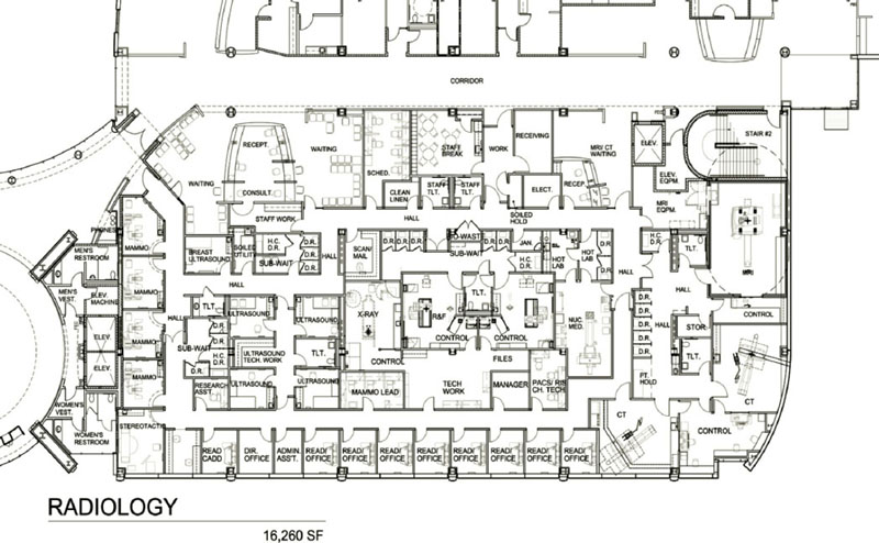
Figure 6-15. Space plan of diagnostic imaging, 16,260 square feet.
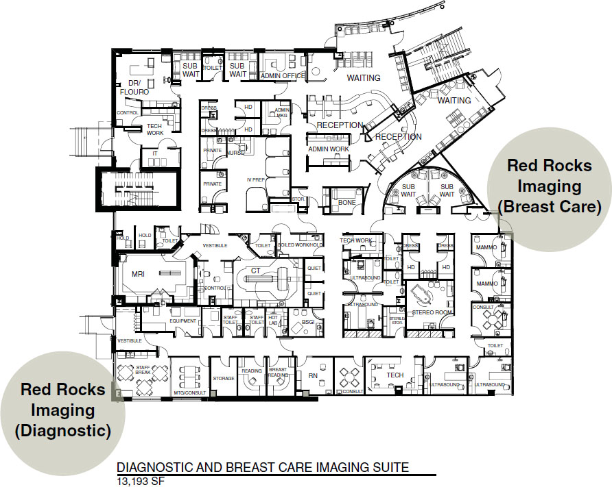
Figure 6-16. Space plan of diagnostic imaging, 13,193 square feet.
In the plans referenced above, the staff area includes a workstation with monitors where technologists can check image quality and prepare the presentation to be passed via the PACS system to the radiologist or, perhaps, the orthopedist. If it is an orthopedic office, as an example, the medical assistant will often make sure the images are on the monitor prior to the physician entering the exam room. Access to the radiologists’ reading room, break room, restrooms, and private offices may be adjacent to the tech work corridor. Plans with a separate staff work hallway prevent patients from overhearing staff conversations and from casually seeing X-ray studies on monitors. It is desirable to protect the patient from overhearing or seeing anything that might cause anxiety or discomfort or constitute a breach of privacy.
One often finds a women’s center within a radiology suite. For marketing purposes, this area is often located near the front of the suite and may even have a private entrance (see Figures 6-15 and 6-16). In Figure 6-14, the women’s center is a separate suite. In Figure 6-16, the subwaiting areas are dedicated to the breast center. This unit functions independently from the rest of the suite, however, staff may travel easily between the breast center and the diagnostic imaging suite.
Staff Flow
Staff flow must be planned carefully with the radiologic technologists who will work in the clinic. Certain imaging modalities such as CT, ultrasound, and nuclear medicine have dedicated technologists. There must be ample space for all of these technologists to pass one another in corridors without bumping into one another and also have adequate monitors and workspace.
Figure 6-13 presents a schematic layout for a radiology suite, indicating separate entries to procedure rooms for patients and for techs as well as other functional adjacencies. It is desirable to provide a separate staff bathroom because patient bathrooms are often in use, and those serving the R/F rooms can get messy. Front office staff function as they would in any medical practice, although the high volume of patients in a radiology suite may necessitate a larger waiting room.
Information Flow
Information flow is dictated by PACS and network system design rather than by space planning. Individual system configurations will be as varied and unique as the enterprises they serve. The locations and number of monitors does not differ appreciably from any contemporary office setting except these happen to be specialized for diagnostic imaging. In the technologists’ work area, there is a need for a document scanner, a CD burner (patients are sometimes given a record of their studies to carry to consulting physicians), and a laser film printer (such as the Carestream DryView 5950 laser imager) to create an analog film version of a digital image. The one area in which there is a huge saving of space, when comparing film-based and digital settings, occurs in storage. With film, large storage capacity is required (as well as structural accommodation to support the weight), whereas an enormous amount of imaging data can be stored digitally in components placed in a small room.
What differentiates one PACS from another is (as with any software) the way it’s configured to meet specific needs in the most user-friendly manner. Intranet access serves referring physicians or radiologists, who are able to log on from remote sites using a password, which then enables them to view images on a PC. They can be located in a remote office and access the system via a local-area network (LAN) or wide-area network (WAN). Each PACS offers different features with the overall goal of enterprise-wide connectivity, eliminating the need to redundantly enter data. Radiology information systems (RIS) such as the McKesson Radiology Manager™ manage workflow, track patients, exams and charges. Another, the NovaRIS™, from Novarad, is a top-ranked integrated PACS/RIS system. A feature of some systems allows for prefetching of pertinent previous studies and reports, bringing them to short-term online storage for quick access.
Some reading this chapter may be designing a radiography suite of two or three exam rooms in an orthopedic group practice. Orthopedists read their own films prior to examining a patient; therefore, a radiologist’s reading room is not required. On the other hand, a multimodality radiology suite of perhaps 10,000 square feet serving a medical office building will have a reading room and a more sophisticated information management system.
Function
A functional layout is one that separates patient and staff flow, as discussed above, and one that has a logical placement of rooms based on patient volume and other considerations. For example, the patient dressing area should be near the procedure (exam) rooms.
The general radiography room for chest films is best located near the front of the suite as these are short examinations, but can be high volume, necessitating a number of dressing rooms nearby. The radiologist’s private office and reading room, on the other hand, should be located in the most remote and quietest part of the suite.
A functional construction issue relates to the size of studs around procedure rooms. Six-inch studs are a wise choice to accommodate the conduit for cabling. Since imaging is such a technologically driven space, 6-inch studs should be considered for other areas, as appropriate.
Flexibility
Flexibility is desirable in any healthcare facility because technology is advancing so quickly that it is hard to forecast space needs 5 or 10 years in the future. As diagnostic imaging rooms are very costly to construct, planning for future expansion is critical, knowing that optimal patient and staff flow can be maintained and the addition of new procedure rooms will not create awkward adjacencies. Flexibility can also be achieved by making rooms larger than the manufacturer’s minimum requirements.
Components of a Diagnostic Imaging Suite
These are the basic components of a radiology suite, and each will be discussed in detail:
- Waiting room
- Business office
- Patient dressing
- Tech work area
- Reading and consultation
- IT room (for server and archives—may be remote)
- Tech work core
- Imaging exam rooms for various modalities
Waiting Room
Allow three waiting room seats per examination room and provide a suitable space out of the traffic lane for a patient in a wheelchair. At times, a patient may be brought in on a stretcher or gurney. This should be taken into account when laying out the space, but it is desirable for the stretcher to be brought through a private staff entrance (rather than the waiting room), through the corridor, and into an examination room, without causing damage to walls or needlessly jostling the patient. A number of patients may be on crutches or use assistive ambulation devices like walkers and scooters, which means there should be more than the usual circulation space.
In a large radiology facility, the number of chairs in the waiting room can make it look like a bus station. It is preferable to divide the seating into privacy groupings, providing several styles of seating to accommodate individual comfort. Color Plate 20, Figures 6-17 and 6-18 present a beautifully designed reception/waiting area with a glass enclosure around registration that provides privacy as well as the ability of staff to monitor the room. Ceiling design and lighting offer variation and interest. Although this is a 27,000-square-foot facility located in a hospital, it also serves outpatients; the design is so outstanding that it merits inclusion in our discussion. It would be hard to find a more attractive diagnostic imaging environment; this should be celebrated as diagnostic imaging is an area that rarely gets any design attention beyond functional equipment layout. Because the St. Joseph’s facility is primarily below-grade, the design concept creates the illusion of nature to surround the patient with design features carried into procedure rooms and prep areas (see Color Plate 21, Figures 6-32a and b). In the lobby, textures of black river rock and a large wall of dark charcoal stone are offset by a glass wall etched with trees and emerald green accent walls. Landscape murals of flower fields create a psychological escape into nature for patients in the holding bays. Throughout, careful lighting design is used to highlight textures.
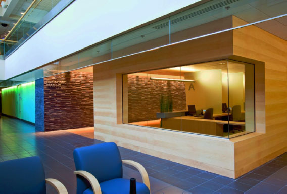
Figure 6-17. Radiology check-in.

Figure 6-18. Radiology waiting area.
Business Office
The business office is generally not large in a radiology suite, because this is a referral practice (Figure 6-19). The radiologist electronically archives only the X-ray images and a brief report on each patient as well as whatever records the referring physician may have sent. Billing and bookkeeping may be done within the suite or at another location. In a fully digital setting, an integrated data management system handles billing and insurance claims, inventory of supplies, and reports to referral physicians, as well as manages all the radiographic digital images. Radiographic images for the recent weeks or months would, of course, be online, accessible from the PACS server for the radiologist in preparing reports. A workroom may be needed for machines like a copier, fax, shredder, document scanner, printer, and possibly a postage machine. This equipment requires quite a bit of countertop space. Storage for business supplies and some paper goods is also needed. Even paperless offices need note pads, envelopes, and so forth.
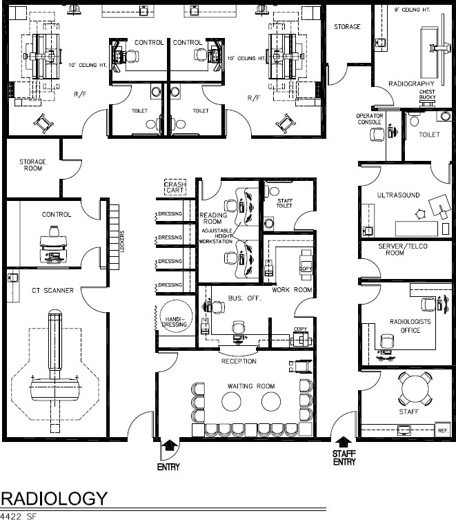
Figure 6-19a. Space plan of radiology suite, 4,422 square feet.
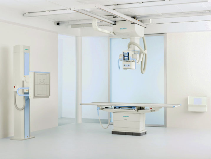
Figure 6-19b. Digital radiography room, Ysio.
It is common for radiology groups to sign contracts with hospitals to staff their radiology departments. It is not unusual for one large radiology group to staff three hospitals in a city, in addition to staffing and owning a number of outpatient radiology clinics in various medical buildings throughout the city. If such is the case, bookkeeping and billing might be done offsite at a centralized location for all of the clinics. Likewise, archiving of nearline and offline images may also be at a central location.
Patient Dressing
Allow two dressing rooms for each exam room. Each needs a chair or built-in bench, mirror, shelf for disposable gowns, and one or two hooks for clothing (see Figure 6-16). A proportional number of dressing rooms must be handicapped accessible. According to the Americans with Disabilities Act 2010 Guidelines, 5 percent of dressing rooms (but no fewer than one) must be accessible. Taking into account the clear area in front of the bench to enable a wheelchair to turn around, the room dimensions would be close to 6 × 8 feet in size. There are numerous specific details such as mirror placement, critical heights, and so forth that need to be followed. Regulations change, making it imperative to consult codes prior to design. Widespread differences exist in ADA interpretation between states and even municipality enforcement within a state.
Sometimes dressing rooms have an emergency buzzer for summoning staff. In a clinic with a sufficient number of dressing rooms, patients may leave their personal effects in the dressing room, which should have a lockable compartment for handbags, briefcases, or jewelry if the room cannot be locked. It is actually preferable to have lockers outside dressing rooms so that others may use the room as in Figure 6-14, which also serves as a subwaiting area. The dressing area should be carpeted, since patients may be walking barefoot.
Gowned Waiting. Certain procedures require disrobing and gowning. Typically, these are cloth gowns that need to be collected after use in a soiled linen bin that needs to be conveniently located. Men and women may sit in a unisex subwait room (see Figures 6-14 and 6-16) or they may enjoy more privacy by waiting in a private dressing room located close to the procedure room until called (Figures 6-20a and b). These dressing/consult rooms offer a degree of privacy, amenities, and design that far exceed what is often found in diagnostic imaging facilities.
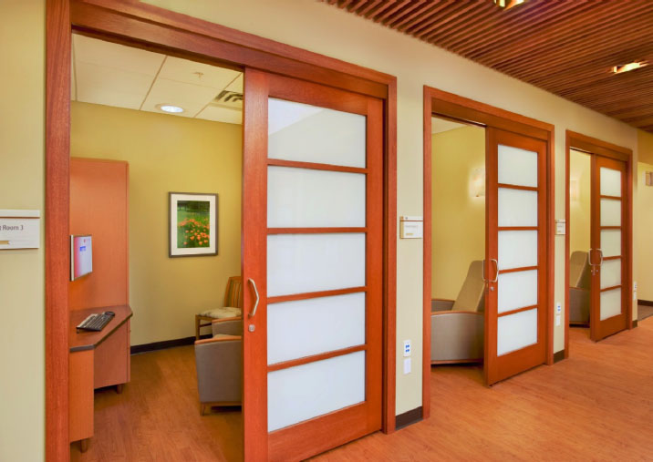
Figure 6-20a. Diagnostic imaging private consult/exam rooms with storage units for personal belongings surrounding the subwait central nurse station.
Stay updated, free dental videos. Join our Telegram channel
VIDEdental - Online dental courses


