Chapter 7
Radiographic Interpretation of Disease
Aim
The aims of this chapter are to:
-
outline the principles of interpretation of DPRs
-
describe some of the disorders that the general dental practitioner may encounter on DPRs in clinical practice. However, it is not the intention of this chapter to provide a comprehensive account of abnormalities of the jaws.
Outcome
After studying this chapter, the reader should have a basic understanding and knowledge of the radiographic features of the more common conditions that affect the teeth and jaws.
Introduction
Radiographic interpretation is the process in which information is gleaned from radiographs. Radiographs are an adjunct to the clinical examination and form part of the diagnostic process. They provide information about disease though its radiographic features. In addition, they are helpful in treatment planning and patient management.
In order to interpret radiographs it is important to have an understanding of the science of image formation. A brief outline follows, but for a fuller account the reader is referred to Chapter 1 of ‘Interpreting Dental Radiographs’ by Horner et al. (2002), and other more detailed texts.
Image Formation
Images are formed on radiographs because of differential absorption of x-ray photons as they pass through the tissues. X-ray absorption is proportional to the cube of the atomic number (Z3) of the absorber and to its density, but inversely proportional to the cube of the photon energy of the x-ray beam (1/E3). High atomic number or dense substances such as gold or enamel are more radiopaque than less dense or lower atomic number materials such as dentine, the soft tissues and, in particular, air, which show varying degrees of radiolucency. So the radiographic image is made up of a range of shadows of different shades of grey, depending on the physical make-up of the tissues and the exposure factors used.
The image of a DPR consists of a zone of sharpness that corresponds to the shape of the jaws. This curved focal trough is narrower anteriorly than posteriorly. Only those objects in the centre of this layer are accurately depicted whilst objects at the margins of the focal are blurred and distorted (see Chapter 6).
When examining a DPR, it is important to bear in mind that the image has less resolution than of intraoral radiographs. This is because:
-
the intraoral radiographic image is formed directly on the film emulsion, whereas in dental panoramic radiography the image is formed mainly by light emitted from the intensifying screens. This light diffuses in all directions from the screens before reaching the film, resulting in a degree of blurring.
-
the panoramic process involves movement which inherently produces some unsharpness, whereas there is no movement of tube or film in intraoral radiography.
Principles of Radiographic Interpretation
It is all too easy in a busy surgery to hold a radiograph up to a bright room light or a window and give the radiograph a cursory glance. Whilst this approach may reveal gross radiographic features, more subtle diagnostic information can be missed.
So How Should One Examine a DPR?
It is important to study any radiograph both systematically and thoroughly. A suggested scheme is listed below.
Use appropriate viewing conditions
A light box, which:
-
has even illumination of optimal brightness (remember that a fluorscent tube gradually looses brightness and so requires periodic replacement)
-
is well maintained, and clean
-
is large enough to accommodate the whole film
-
has a high intensity light source to examine dark areas of the film
Exclude or mask off light peripheral to the radiograph to reduce glare. This permits the pupils to dilate allowing the eyes to gather more information.
Where possible view radiographs in subdued, ambient lighting in a quiet distraction free environment.
Use magnification. Although this is particularly pertinent to examining intra-oral radiographs, it is also helpful when viewing problem areas on DPRs.
Examining radiographs in this way is less tiring on the eyes, improves radiographic contrast and maximises radiographic detail.
Be familiar with the normal panoramic image
It is essential to be able to recognise normal anatomical structures and variations of normal features in order to identify an abnormality. This includes both the hard and soft tissues, ghost shadows and image artefacts that occur with DPRs (Chapter 3).
Assess image quality (see Chapter 6)
Poor image quality results in loss of diagnostic information. This can arise from inappropriate film processing or exposure factors producing radiographs that are excessively pale or dark, whereas inaccurate radiographic technique results in image distortion.
Examine the radiograph systematically
-
Use continuous eye movements rather than staring at one point.
-
Follow or trace all anatomical outlines checking for discontinuity, displacement or destruction. This usually requires several ‘trips’ around the film.
-
Check for lack of symmetry by comparing left and right sides and if present decide whether it is significant.
Familiarise yourself with disorders of the jaws
It is important to have an understanding and knowledge of the diseases that affect the jaws, their histogenesis and behaviour. For example, radicular cysts show unicystic growth, expand equally in all directions and appear round, whilst keratocysts are elongated because they enlarge along the cancellous bone due to difficulty in resorbing and expanding the cortical plates. Odontogenic disorders arise in or are centred on the alveolar parts of the jaws, so an abnormality confined to the basal bone is probably not of odontogenic origin.
Relate what you see to the clinical findings
Age, gender, race, the clinical history, the clinical examination and the results of special tests provide useful information for radiographic diagnostic process.
Use previous radiographs
These provide information on the presence or absence of pre-existing disease and on the progression of existing disease.
When examining a DPR, remember the limitations inherent in the panoramic image. It is a very useful view for many conditions, but don’t forget that additional views may be needed to obtain a fuller picture. For example, a view at right angles (e.g. lower true occlusal view) to show jaw expansion, or parallax views to assist with location of unerupted teeth or foreign bodies may be needed.
This chapter now briefly describes some of the conditions that can appear on DPRs, under the following headings:
-
Disorders of the teeth
-
Disorders affecting the jaws
-
Disorders in the soft tissues
-
Disorders of the maxillary antrum
-
Disorders of the temporomandibular joint.
Disorders of the Teeth
Hypodontia
This is a developmental condition in which one or more teeth fail to form. It is more prevalent in the permanent dentition (<7% excluding wisdom teeth) than the primary dentition (<1%). It particularly affects third molars, lower second premolars and maxillary lateral incisors. Its severity varies from absence of one tooth (common) to complete failure of development of the dentition or anodontia (rare).
Absence of a permanent successor often leads to prolonged retention of the primary predecessor. This can result in ankylosis of the primary molars, which may then submerge due to bone remodelling. Fig 7-1 shows a patient with hypodontia.
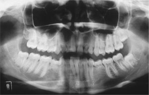
Fig 7-1 Hypodontia. The upper lateral incisors, upper and lower second premolar, and the upper right wisdom tooth are absent. There is retention of the upper primary canines and lateral incisor, and the lower primary second molars.
Certain syndromes are associated with hypodontia, some of which are outlined in Table 7-1.
| Disorder | Associated features |
| Ectodermal dysplasia | Numerous missing teeth, conically shaped teeth, hypotrichosis, hypohidrosis, saddle-shaped nose |
| Down syndrome (Trisomy 21) | Maxillary hypoplasia, delayed cognitive skills, hearing and vision defects, cardiac abnormalities. |
Hyperdontia
The condition in which there are teeth additional to the normal series is referred to as hyperdontia, or supernumerary teeth. It affects approximately 1% of the population and occurs mainly in the permanent dentition, particularly in the upper central incisor, and the molar and premolar regions of the jaws.
The types of supernumerary teeth are summarised in Table 7-2. Supernumerary teeth in the maxillary midline region may be poorly displayed on DPRs if unfavourably positioned in relation to the image layer. However, supernumeraries in the posterior regions are usually well shown on DPRs (Figs 7-2 and 7-3).
| Type | Location | Appearance | Features |
| Mesiodens | Either side of the midline of the maxilla | Small and conically shaped | Occurs singly or paired. Can erupt, invert, or prevent eruption of the permanent incisor. Develops chronologically between that of the primary and permanent central incisors. |
| Tuberculate | Either side of the midline of the maxilla, usually palatally located | Small, cusped tooth | Can occur singly or paired. Develops chronologically shortly after the permanent central incisors, and usually prevents their eruption. |
| Supplemental premolars | Mainly premolar or molar regions | Resembles normal premolars or molars | Develops shortly after the adjacent permanent teeth, often remain unerupted. |
| Paramolars | Adjacent to the molar teeth | Small and rudimentary | Situated buccal or lingual to a maxillary molar |
| Disto-molars | Distal to the wisdom teeth | Often small and conical | Occasionally erupt |
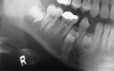
Fig 7-2 Two supplemental supernumeraries at an early stage of development and a displaced, unerupted lower right second premolar.
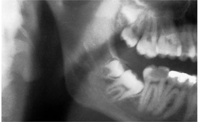
Fig 7-3 Unerupted upper and lower distomolar with incomplete root development. The lower right third molar is impacted and the second molar is grossly decayed.
Whilst supernumerary teeth may be an isolated anomaly, they are also found in certain systemic disorders, e.g. Gardner’s syndrome and cleidocranial dysplasia (Fig 7-4). Cleidocranial dysplasia is associated with multiple supernumerary and unerupted teeth (Fig 7-4).
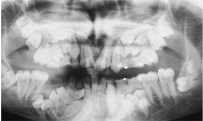
Fig 7-4 Cleidocranial dysplasia, showing numerous unerupted permanent and supernumerary teeth. Very few of the permanent teeth have erupted.
Impacted Third Molars
Lower wisdom teeth often fail to fully erupt because of insufficient room to accommodate them into the dental arch. Impacted, partially erupted wisdom teeth are prone to develop caries and/or pericoronitis. Although the DPR is usually perceived as the most appropriate view to image impacted wisdom teeth, there are alternatives views. (Table 7-3).
| Technique | Advantages | Disadvantages |
| DPR | Shows all four wisdom teeth. | Relative lack of image definition. |
| Shows full depth of mandible. | Long exposure time-patient must keep still. | |
| Good patient compliance. | Dose may be larger than periapical views | |
| Oblique lateral mandible | Alternative to DPR. | Relative lack of image definition. |
| Shows upper and lower wisdom teeth on one side. | Short exposure time. | |
| Technique simple with good patient compliance. | Some image distortion. | |
| Periapical radiographs | Good image definition. | Poor patient acceptance due to lack of depth and sensitivity of lingual sulcus. |
| Useful for examining single wisdom tooth. | Unsuitable for patients with a tendency to gag or limited mouth opening. | |
| Vertical parallax views can be used to help identify position on the IDC. | Not suitable for deeply placed wisdom teeth. | |
| Widely available. |
The radiographic assessment of impacted wisdom teeth has been described in Chapter 8 of ‘Interpreting Dental Radiographs’ by Horner et al. 2002, to which the reader is referred. For ease of reference, a scheme is outlined below that contains the key features for assessing an impacted lower wisdom tooth.
Nature of impaction
-
type of impaction; soft tissue, tooth, bone, or a combination of these.
-
angulation of impaction, relative to that of the vertical axis of the lower second molar. The types are: horizontal, mesio-angular, vertical, disto-angular, transverse (rare). Whilst horizontal impactions may look difficult, distoangularly impacted wisdom teeth often prove troublesome to remove, due to the close approximation of the roots of the wisdom tooth to the second molar roots and the lack of access and space to deliver the tooth.
Status of crown
Assess whether sound, carious and/or bulbous. Decay is common in those teeth susceptible to food stagnation, notably partly erupted, mesio-angular or horizontally impacted wisdom teeth.
Root morphology (Fig 7-5)
-
stage of root development
-
number of roots
-
curvature
-
size
-
bulbosity
-
proximity to the inferior alveolar canal.
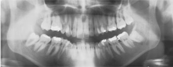
Fig 7-5 Both lower wisdom teeth in this patient are mesio-angularly impacted, the lower right having a conical root, the apices lying close to the inferior alveolar canal.
Wisdom teeth with roots that are short and conical are easier to remove than those with multiple, long and curved roots.
Association with the inferior alveolar (dental) canal
It is essential to determine the proximity of the root to the inferior alveolar canal. An association is present if there is change to the root where it is crossed by the canal, or change to the canal where it crosses the root. These changes are depicted diagrammatically in Fig 7-6. An example of a close relationship of tooth and canal is shown in Fig 7-7.
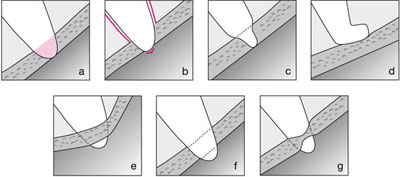
Fig 7-6 Line diagrams illustrating the different radiographic appearances of roots grooved by the inferior alveolar canal. a) change of density (radiolucency) of the root; b) loss of lamina dura around the root where it is crossed by the canal; c) constriction or narrowing of the root; d) curvature or hooking of the root where it abuts up against the roof of the canal; e) change in direction of the canal as it crosses the root; f) loss of one or both of the cortical outlines (tramlines) of the canal; g) constriction or narrowing of the canal.
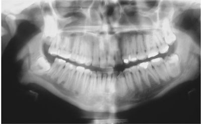
Fig 7-7 Both lower wisdom teeth roots are grooved by the inferior alveolar canal. Note the deviation of the canal on the right side and the radiolucent band at the root apex of the lower left wisdom tooth where it is crossed by the canal. The lower left wisdom tooth is carious.
Other features to assess
-
Depth of tooth in bone/bone level; the amount of bone covering the crown.
-
Density of the investing bone, the size of the marrow spaces and the number of bony trabeculae.
-
Size of follicular space; normally 1 to 2 mm, but often enlarges following recurrent pericoronitis. If wider than 5 mm, indicates pathological change, such as dentigerous cyst formation.
-
Condition of the remaining dentition, in particular presence of dental caries and periodontal bone loss.
Maxillary Canines
After the third molar, the maxillary canine is the second commonest tooth to fail to erupt, with up to 2% of the population being affected. During its eruption it is guided into position by the distal aspect of the root of the maxillary lateral incisor. By the age of 10 years, the crown of the unerupted canine is usually palpable as a smooth, domed expansion of the buccal alveolus. If the canine is not palpable by this time, it is probable that its eruption is abnormal and so requires further investigation to confirm its presence, to assess the likelihood of its eruption and whether treatment is required to assist its eruption. An intra-oral view (or parallax views) may be all that is required, but a DPR is indicated when it necessary to assess other unerupted teeth, as for example with orthodontic treatment planning.
Whilst a DPR will image unerupted canines, it may be of limited value for those teeth that are not completely located within the focal trough.
Radiographic assessment should include:
Position:
An unerupted maxillary canine may be placed, palatally, buccally or lie in the arch.
On a DPR, the width (mesio-distal dimension) may be used to determine the position of a canine in the arch. Assuming there is no radiographic distortion, if the canine appears wider than normal (compare with the contralateral erupted canine) it suggests that it lies palatally. This is because objects on the medial aspect of the focal trough appear magnified (and also less sharp). The converse is also true, i.e., a buccally displaced tooth will appear narrower than normal (Fig 7-8).
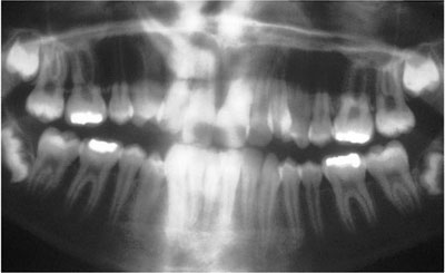
Fig 7-8 A DPR showing how position of ectopic teeth will influence their image on the DPR. In this case the right canine is widened (palatal position) and the left canine narrowed (buccal position).
Although the width of a maxillary canine image on a DPR is a useful guide to its location, confirmation may still be required. This can be achieved by taking an upper occlusal radiograph of the canine, which is viewed by placing it above the panoramic film and parallax applied in a vertical direction (Fig 7-9, a and b). In parallax, two views are taken of the same area but with a different tube angulation. If the object (canine crown) moves in the same direction as that taken by the tube shift relative to a fixed object (lateral incisor root) it lies palatally, whilst if it moves in the opposite direction to that taken by the tube, it will lie on the buccal side.
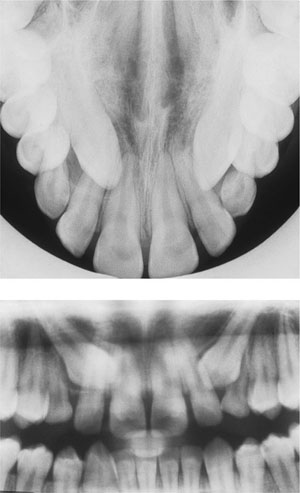
Fig 7-9 a) Upper anterior occlusal view showing two unerupted maxillary canines and b) DPR of the same patient. The tube angle for the occlusal film is 60–65° downwards, but approximately 8° upwards for the DPR. Note that the crowns of both canines are located higher up the lateral incisor root (closer to the apex) on the occlusal film 7.9.a, when compared with the DPR. Thus, they are seen to move in the same direction (downwards) as the tube angulation changes from the occlusal to the DPR, so confirming its palatal displacement.
Note the degree of angulation of the canine relative to the adjacent teeth and the amount of space between the adjacent teeth.
Crown
Stay updated, free dental videos. Join our Telegram channel
VIDEdental - Online dental courses


