Chapter 2
Dental Panoramic Radiographic Technique
Aim
The aims of this chapter are to outline the principles of panoramic image formation and the technique of dental panoramic radiography.
Outcome
After studying this chapter the reader should have an understanding of the basic concepts of dental panoramic image formation and the technique of obtaining a dental panoramic radiograph.
Introduction
Demonstrating the whole of both jaws on a single film is an advantage, particularly for assessing disorders too large to be recorded on intraoral radiographs or as a substitute for conditions requiring multiple intraoral films. If a Dental Panoramic Radiograph (DPR) is to be of optimal clinical value, it must be performed accurately and the resultant films correctly processed. The procedure of taking a DPR may seem reassuringly straightforward, but in fact it is technically exacting and requires attention to detail. Mastering the technique is made easier if you have a clear understanding of how the image is formed and of the image characteristics.
Panoramic Image Formation
The theory of panoramic image production is complex and beyond the remit of this book. However, a brief outline is provided, but for a more comprehensive account the reader is referred to other texts.
Obtaining a satisfactory single image of both jaws without distortion or superimposition of other structures is complicated because of their horseshoe shape. One solution to this problem is to record a curved slice that follows the shape of the jaws. The slice recorded in dental panoramic radiography is of variable width, being about 10 mm anteriorly and 25 mm posteriorly. The region imaged extends from the level of the orbital floor to the just below the lower border of the mandible. The curved object (the jaws) is displayed as a flattened out ‘panoramic’ picture which is created by using slit beam scanning and a form of tomography.
Tomography
Tomography is a technique that uses synchronous movement of an x-ray tube and film cassette carrier, which are linked by a rod that rotates about a pivot point. During the exposure the cassette holder moves in one direction whilst the x-ray tube moves in the opposite direction, as shown in Fig 2-1.
-
An object at the pivot point (B) appears at the same place on the film whilst objects above and below this plane have a different linear velocity and so are not sharply shown. Thus objects in plane B are clearly depicted, but objects in other planes, as shown by the letters A and C, are blurred or stretched out and thus not recognisable because they appear in different places on the film.
-
The position of the image layer can be adjusted within the object by raising or lowering the pivot point.
-
A wide angle of tube and cassette movement results in a narrow zone of sharpness, whilst a small angle of travel in broad zone of sharpness, as illustrated in Fig 2-2.
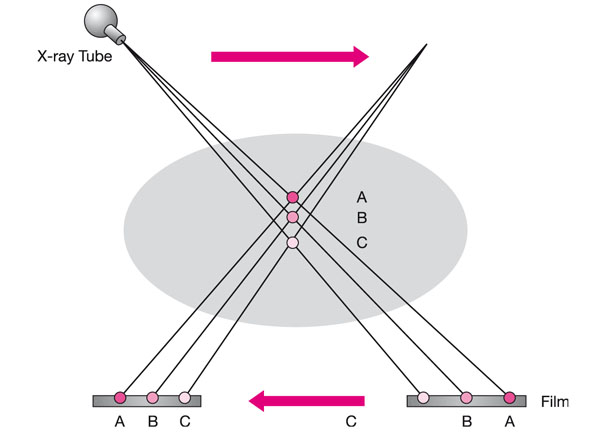
Fig 2-1 Diagram illustrating the principle of tomography.
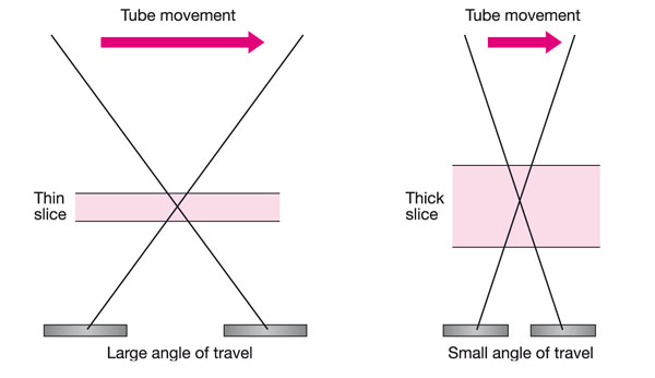
Fig 2-2 Image layer thickness is determined by angle of travel.
So tomography produces an image of a flat plane, but to record the teeth and jaws it is necessary to image a curved plane that corresponds to the shape of the jaws.
The shape of the jaws can be thought of consisting of the arcs of three circles, as shown in Fig 2-3. The centre or pivot point of each circle is shown by the numbers 1 2 & 3, with their respective arcs. To obtain this curved slice, it is necessary for the tube and cassette carrier to rotate sequentially about these three pivot points. The wide angle employed at the front of the jaws produces a narrow slice.
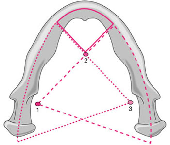
Fig 2-3 Shape of the jaws consisting of the arcs of three circles.
However, using fixed or stationary centres of rotation results in high radiation doses at the pivot points. This can be overcome by continuously moving or sliding the centres of rotation along a curved path between the three centres, as shown in Fig 2-4.
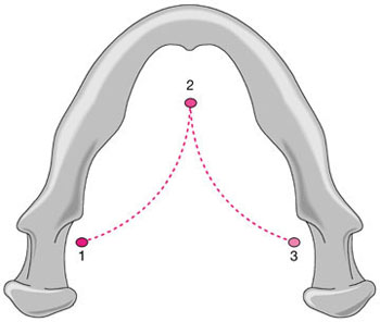
Fig 2-4 Rotation centres sliding from one centre to another.
Slit Beam Imaging
Unlike a conventional dental x-ray set, the panoramic x-ray tube head is designed/>
Stay updated, free dental videos. Join our Telegram channel
VIDEdental - Online dental courses


