APPROACHES TO TREATMENT OPTION SIX
OSSEOINTEGRATED FIXTURE SUPPORTED PROSTHESES
(using the Brånemark system)
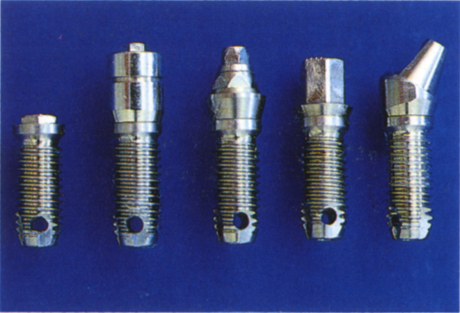
There are six situations in which osseointegrated fixtures may be used in treating a patient with failure in a restored dentition. These are:
- Replacement of a section of the restoration, the replacement being totally fixture supported (Figs 33-1a–b; 33-21).
- Replacement of a section of the restoration, with linkage to tooth abutments (Figs 33-20 + 21).
- Removal of all remaining tooth abutments and replacement with a fixture supported prosthesis (Figs 33-15 + 19).
- Removal of all remaining tooth abutments and replacement with an overdenture prosthesis (Figs 31-3a + 33-14).
- Replacement of a single tooth with a fixture supported crown (Figs 4-27 + 33-21).
- The placement of ‘sleeping’ fixtures (Fig 33-1d). Fixtures are placed but are left unexposed and are then available for future use, if necessary. Thus, if there are edentulous areas and surgery is required prior to bridge replacement, for example, for crown lengthening, it may be possible to ‘bury’ fixtures at the time of surgery. Should there be further failure later, the tooth abutments may be extracted and the fixtures exposed. In consequence, there is a minimal transition period between extraction and conversion to an osseointegrated fixture supported prosthesis.
Indications for Osseointegrated Fixture Supported Prostheses
- When failure is so extensive that reconstruction solely on tooth roots is unwarranted (Figs 33-1b, 33-19, 33-20 + 21).
- When fixed bridgework supported by teeth has a poor prognosis and the patient is adamantly opposed to a removable denture or would not be able to tolerate one due, for example, to a severe retching problem, or an unfavourable, flat endentulous ridge morphology with shallow sulci (Fig 33-19).
- When the removal of part of a restoration results in an edentulous area, the treatment of which would require re-restoration of adjacent teeth and possible destruction of sound existing bridgework in order to extend it to incorporate the endentulous area (Figs 33-1a–b).
- When treatment of failed distal units will require free end saddle partial dentures as part of the restoration (Figs 33-1a–b, 33-20).
- When removal of failed units leaves insufficient tooth support for replacement bridgework. Some sections may be replaced with osseointegrated prostheses (Figs 33-1a, 33-20 + 21).
- When removal of failed restorations results in an edentulous or nearly edentulous jaw opposing a fixed reconstruction or natural dentition, particularly if the edentulous jaw has an unfavourable ridge morphology on which to construct a complete denture (Figs 33-16, 33-19a).
Fig. 33-1 Replacement of failed restorations with osseointegrated prostheses.
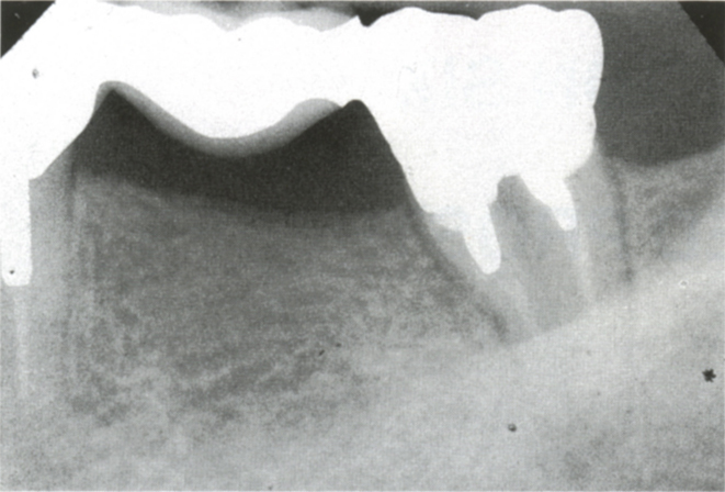
Fig. 33-1a (i) Replacement of a small section of failed bridgework with a totally osseointegrated fixture supported bridge. Repeated abscess formation on 37. Sclerosed pulp canals, caries in furcation. Prognosis for re-restoration is poor.
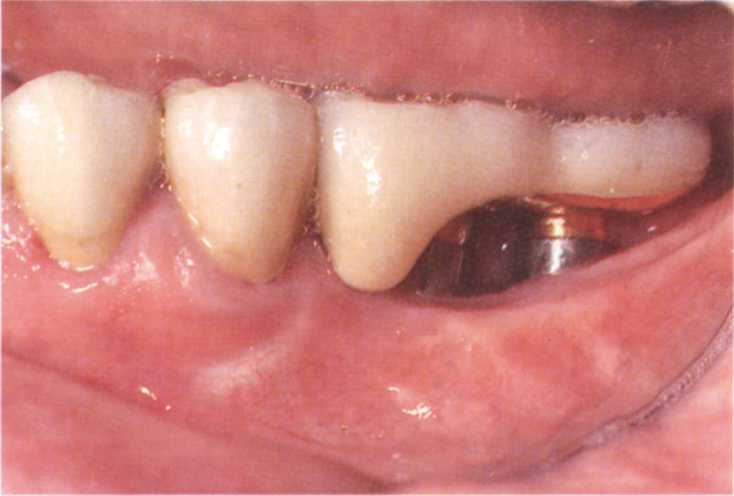
Fig. 33-1a (ii) Bridge sectioned distal to 35. Following eight weeks of healing, 2 × 10 mm × 3.75 mm Brånemark fixtures were placed. The fixture supported bridge was designed with a buccal facade for the mesial crown, since the patient showed this when smiling. There is easy access to the abutment for maintenance. A shorter abutment built out mesially would have created a difficult space to clean. Remaking the bridge with a cantilever unit from the natural roots without fixture placement would have necessitated removal of the well-fitting crowns on 34 and 35 and the crowning of 33 (surgery by Mr B. O’Riordan).
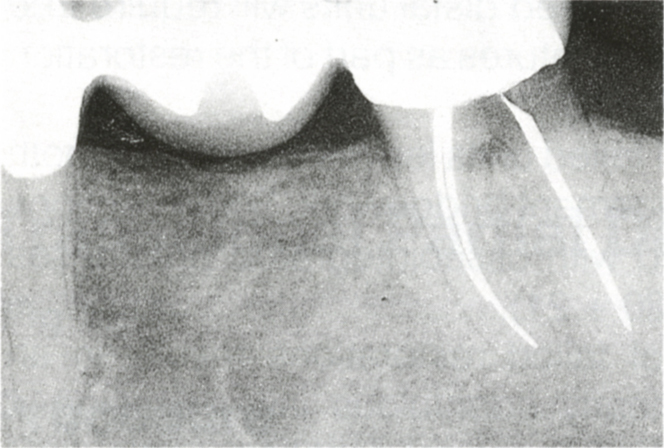
Fig. 33-1b (i) Caries on the distal of 37. Restoration would require root division and possibly hemisection, removal of the caries which would shorten the root, osseous resection to expose sound tooth on the distal root, re-root filling and fabrication of a post and core on the shortened root. The final bridge would have a poor prognosis.
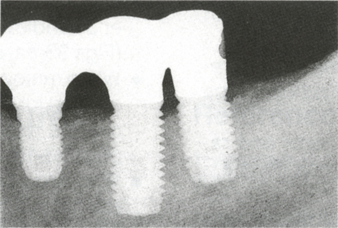
Fig. 33-1b (ii) A 7 × 3.75 mm, a 10 × 5 mm and an 8 × 5 mm fixture were inserted four months after extraction of 37 in preparation for a fixture supported bridge – this has a better prognosis than a fixed bridge using the tooth and obviates the need for a free end saddle partial denture.
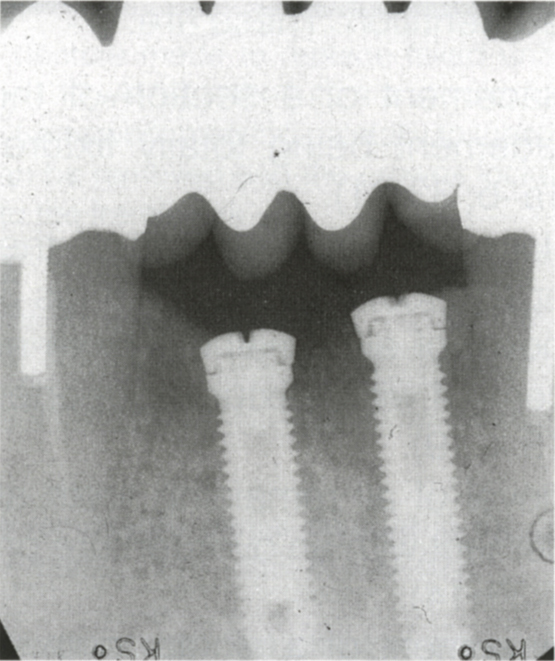
Fig. 33-1d “Sleeping” fixtures for future use. If the bridge, which was part of a reconstruction was to fail, the fixtures could be exposed and used.
Factors which should be Considered
Factors Related to the Clinician
- Training
- Ability
- Experience
- Availability of surgeon, prosthodontist, technician
- Availability of diagnostic facilities
- Availability of proper surgical facilities
Factors Related to the Patient
- General health
- Attitude
- Local health:
mucosa
bone
teeth
periodontium - Morphological features of the field of operation:
cross sectional ridge form
bone quality
bone width
bone height - Length of the edentulous span and its relationship to adjacent teeth
- Curve of the edentulous span
- Relationship of the proposed fixture sites to vital structures
- Relationship of the proposed fixture sites to the opposing jaw
- Relationship of the proposed fixture sites to the anticipated position of the replacement tooth
- Smile line
- Facial aesthetics
- Phonetics
- The transition from the existing restoration to the fixture supported restoration
- Keratinization of the mucosa around the fixtures
- Maintenance
Factors Related to the Biomechanics of Fixture Supported Prostheses
- Whether to join the fixture supported sections to adjacent teeth
- Framework design and choice of materials
- Occlusion and the materials for the occlusal surfaces
- Choice of articulator
Factors Related to the Type of Prosthesis
- Overdenture
- Fixed bridge
Training
It is imperative that the clinician has attended suitable courses. These should not only demonstrate technique, but also consider the biological aspects. They should enable the clinician to evaluate critically, the efficacy of the available systems and for this purpose long-term clinical and basic research data are necessary. The choice of a system should not be based upon a manufacturer’s advertising, or anecdotal presentation of individual cases by clinicians. All possible steps should be taken to ensure that failure of the existing restoration is not followed by failure of its replacement. Failure following the use of implant systems based on inadequate clinical and laboratory data could have important medico-legal implications for the dentist.
Ability
Clinicians must be objective about their own ability. Treatment must not be attempted for cases beyond the competence of the operator. Referral must be considered.
Experience
The recommendation of the Brånemark group is that initially, treatment should be restricted to favourable anterior lower jaw sites, where the outcome is most predictable. Difficult maxillary sites should only be attempted after experience has been gained.
Availability of Surgeon, Prosthodontist, Technician
It must be decided whether the clinican will provide all phases of treatment, or whether to adopt a team approach. As with other aspects of restorative dentistry, overall control, treatment planning and co-ordination should be the prosthodontist’s responsibility, with the services of other specialists called upon as necessary.
Availability of Diagnostic Facilities
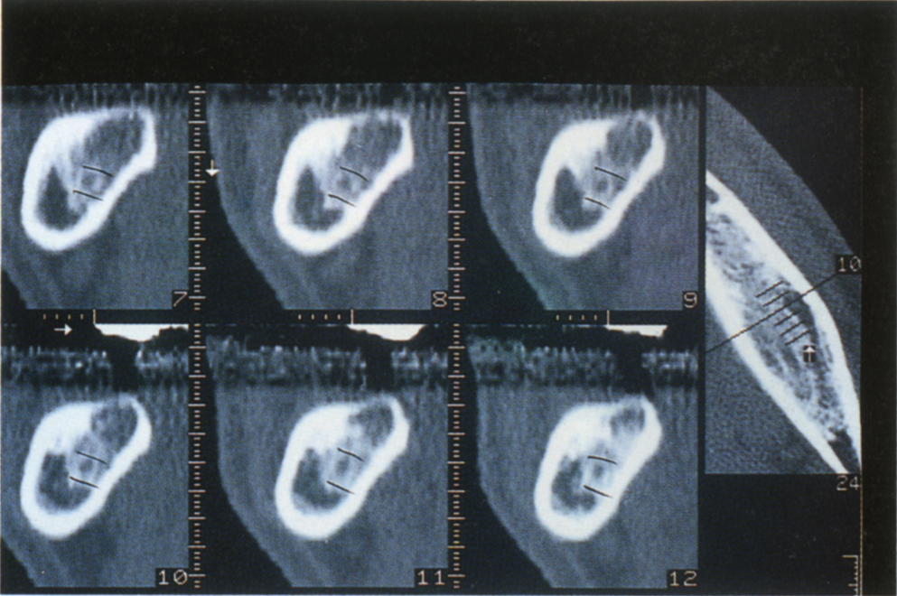
As with all forms of treatment, the more complete the diagnosis, the less likely that inappropriate treatment is carried out and the better the prognosis. All cases will initialy require a dental panoramic tomogram (DPT), a long cone parallel beam periapical series of selected areas and possibly, a lateral cephalostatic view. Diagnosis, however, can be greatly facilitiated by tomographic views or computerized tomography (CT) with cross sectional reformatting (Figs 33-7, 33-9). These give very accurate data about the cross sectional dimensions of the jaws. Permanent damage to the inferior dental nerve resulting from surgery which was carried out without reference to tomograms or CT scans, could have unfortunate medico-legal consequences for the operator.
Availability of Correct Surgical Facilities
A sterile working environment with correct instrument layout and trained assistance is absolutely essential. In the absence of such facilities, implants should not be embarked upon.
Related to the Patient
General Health
According to Lekholm and Zarb (1985)1 and corroborated by Smith et al. (1992)2 ‘age does not appear to influence patient selection, nor does a large number of chronic health conditions. Thus patients with medical conditions, such as (controlled) diabetes, arthritis and cardio-vascular diseases have been operated on, as well as patients on long-standing steroid medication, without any adverse long-term effects. Such patients will, of course, require conventional precautions throughout the entire surgical intervention’.
Many of the risks are those related to general anaesthesia, which may be overcome by use of local anaesthesia and sedation techniques. General surgical risks, such as excessive haemorrhage in patients on anticoagulant therapy must be controlled in the appropriate manner. Patients should be specifically questioned about aspirin use, because it can be purchased without prescription, patients may not consider aspirin medication, however, it can influence blood clotting. Surgery should be delayed for two years following radiotherapy and the patient should be provided with a general anaesthetic to avoid additional soft tissue trauma and the vasoconstriction of a local anaesthetic.3 Hyperbaric oxygen therapy may be valuable.3 Severe osteoporosis and long-term steroid therapy can result in poor bone quality, jeopardizing the prognosis. However, Dao et al. (1993),4 after an analysis of the literature, concluded that osteoporosis is not a risk factor. Uncontrolled diabetes and alcohol or drug abuse may compromise wound healing and home-care and require a cautious approach to treatment, testing first the response in sites with the best prognosis prior to commencing treatment in less favourable sites. Renal dialysis alters the calcium/phosphorous balance and may, therefore, influence bone metabolism. Fixture placement is contraindicated in patients undergoing dialysis and in patients undergoing chemotherapy.
Cigarette smoking impairs the outcome of periodontal surgical therapy5 and similarly, smokers have a significantly greater percentage of fixture failures (11.28%) than do non smokers (4.76%).6 If possible, it is sensible to try and restrict smoking for one month prior to surgery and for one month subsequently. However, realistically this may not be viable. (The efficacy of this recommendation has not been tested.)
Attitude
It is important to assess the patient’s attitude in relation to:
- Reasons for treatment
- Any psychological problems
- Realism, regarding timing
Reasons for Treatment
Patients seeking treatment because of an inability to masticate or other functional difficulties related to a mobile prosthesis, and some cases of poor aesthetics are good candidates for treatment.7 However, patients who are unaware, until told, that existing work had failed, or who are trying to regain lost youth by having teeth ‘fixed-in’ may present problems. A patient in the former category who is subjected to a course of treatment requiring a long period of time may acknowledge that they understand how long treatment will take, but in reality they dismiss this and subsequently become very agitated. The patient who is trying to regain lost youth may require more than a fixed dentition to fulfil their requirements.
Psychological Problems
Patients with problems of psychogenic origin may become convinced that provision of a stable dental occlusion will cure their problems (see Chapter 27). Although osseointegrated prostheses may provide the occlusal stability, if the psychogenic problem remains unresolved the problem can remain. Disappointment may lead to litigation by the patient.
Kiyak et al. (1990)7 reported a correlation between high scores of neuroticism and less satisfaction with treatment results. Such patients should not be denied treatment, but require more supportive therapy, as do those who are taking psychotropic drugs.
Realism, Regarding Timing
In the lower jaw, there will be an interval of at least three to six months between the placement of the fixtures and their use for supporting a prosthesis. In the maxilla there will be a six month interval. Furthermore, if, as is common with existing failure, extraction of teeth or ridge augmentation are required, it may be necessary to wait nine to 12 months before the fixtures can be placed, thereby increasing the timespan. However, techniques have been described for the placement of fixtures directly into extraction sites, ‘encouraging bone regeneration and integration’ through the exclusion of epithelial downgrowth.8 These procedures should not be used in the presence of periapical infection. It is, however, preferable to wait at least six weeks following extraction to allow wound closure to occur, with epithelialization over the extraction site. The incision at fixture placement can then be remote from the fixture site and a good seal obtained with vertical matress sutures, so that the fixtures are isolated from the oral environment during osseointegration.
Sometimes, it is particularly difficult to ensure the patient is comfortable and functioning with a fixed prosthesis during the transition stage from failed bridgework to osseointegrated fixtures. It is often necessary to extend the duration of treatment to retain some useful abutments during the healing phases (Figs 33-14d, 33-15, and 33-16). The patient must be realistic about the timescale that is involved.
Local Health
Mucosa
Mucosal lesions such as herpetic stomatitis, candidiasis, fistulae and epulides must be treated prior to fixture placement.
Bone
Abnormalities, such as tooth remnants, impacted teeth, cysts, residual bone infections and tumours must be treated and healing allowed to occur prior to the placement of fixtures. Following the extraction of teeth associated with large bony lesions, it is advisable to allow nine to 12 months for healing before fixture placement. Following extraction of teeth which have fractured, or teeth with advanced periodontitis or small periapical areas, it is advisable to wait four to six weeks before fixture placement. Surgery should not be delayed beyond eight weeks, since bone resorption may occur with consequent unnecessary compromise of fixture length and aesthetics. It is sometimes possible, when extracting teeth with advanced periodontitis, to reduce the bone to the base of the socket. The wide bony shelf, so produced, allows immediate placement of the fixtures.9
Teeth
Carious lesions must be excavated and either dressed or restored to remove a source of infection. Endodontic lesions must be treated. Endodontically involved teeth that are to be retained as abutments for provisional bridgework and then extracted, may be dressed with calcium hydroxide, following debridement and preparation.10–11 Final obturation can be omitted in such cases.
Periodontium
Data from studies by Lekholm et al. (1986),12 Apse et al. (1989),13 Quirynen and Listgarten (1990)14 and Bauman et al. (1992)15 suggest that osseointegrated fixture sites can be colonized by microflora from around the teeth and that periodontal pathogens can accelerate perifixture disease if patients are not well maintained. Furthermore, animal experiments16 indicate that lesions in the tissues surrounding fixtures, but not those around teeth, extend into the bone marrow. This indicates that once established, the spread of infection and loss of alveolar support may be more rapid around fixtures than around teeth.
It is possible that organisms from sites around teeth with periodontitis only invade the perifixture tissues after the failure of integration and do not cause the failure. However, until proven otherwise, it is prudent to assume that they can be aetiologic in perifixture disease. As such, periodontitis must be treated or teeth extracted prior to fixture placement, particularly since Henry et al. (1993)17 reported that in partially edentulous patients, fixture failure was more likely to occur in those patients with relatively high plaque indices before fixture placement. Following treatment, the patient must be maintained so that periodontitis is not re-established. Whether teeth with periodontitis, which are remote from the fixture site, can be retained in an untreated state and what constitutes remoteness has not been established. However, it should be noted that Haffajee (1991)18 reported that pockets of 4 mm or more may act as reservoirs for organisms which may reinfect other periodontal sites. The more residual pockets, the more the chance of reinfection. Treatment must not be confined only to the sites in which fixtures will be placed.
Morphological Features of the Area to be Operated Upon
Cross Sectional Ridge Form
Lekholm and Zarb (1985)1 described five cross-sectional ridge forms for the maxilla and mandible and four jaw bone quality types. The five cross sectional ridge forms encountered are (Fig 33-2):
A. Most of the alveolar ridge is present.
B. Moderate ridge resorption has occurred.
C. Advanced ridge resorption has occurred and only basal bone remains.
D. Some resorption of the basal bone has started.
E. Extreme resorption of the basal bone has taken place.
Jaw Bone Quality
The four types are (Fig 33-3):
1. Almost the entire jaw consists of homogeneous bone.
2. A thick layer of compact bone surrounds a core of dense trabecular bone.
3. A thin layer of cortical bone surrounds a core of dense trabecular bone.
4. A thin layer of cortical bone surrounds a core of low density trabecular bone.
Fig. 33-3a Proposed classification of jaw bone quality. (1) Almost the entire jaw is comprised of homogeneous bone. (2) A thick layer of compact bone surrounds a core of dense trabecular bone. (3) A thin layer of cortical bone surrounds a core of dense trabecular bone. (4) A thin layer of cortical bone surrounds a core of low density trabecular bone.
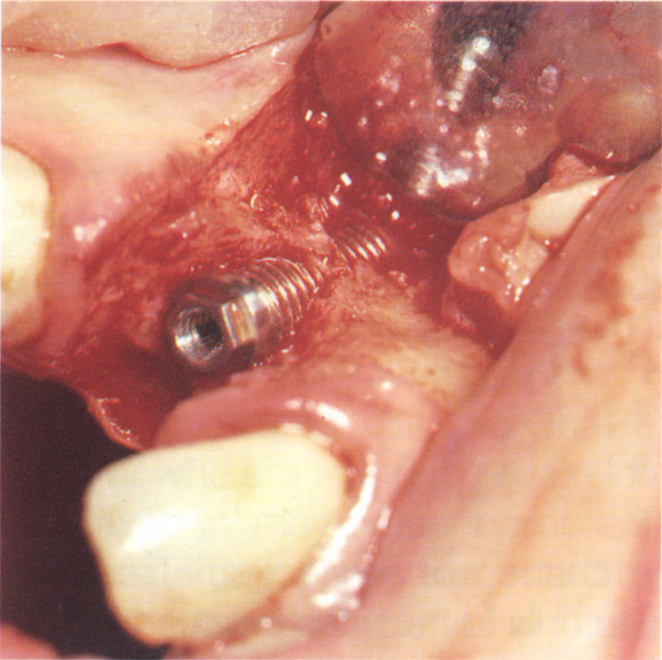
Fig. 33-3b The ridge is narrow, due to loss of the buccal plate of bone. The 15 mm fixture has 5 mm encased in apical bone, but the majority of the remaining buccal threads are exposed.
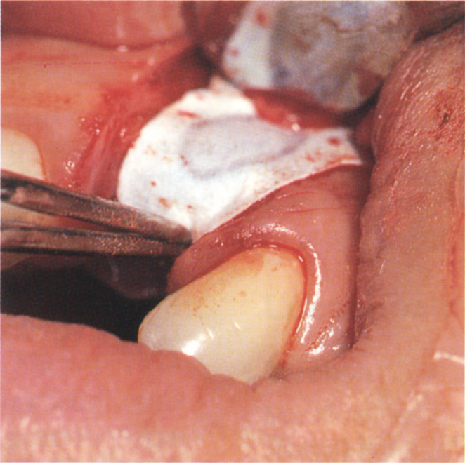
Fig. 33-3c Gore-Tex Oval 4 membrane being adapted to cover the fixture. It tucks under the edge of the palatal flap and the central more rigid portion assists in tenting it out. Bone chips were removed from the alveolus distal and apical to tooth 21 and were used beneath the Gore-Tex to maintain the space over the fixture threads.
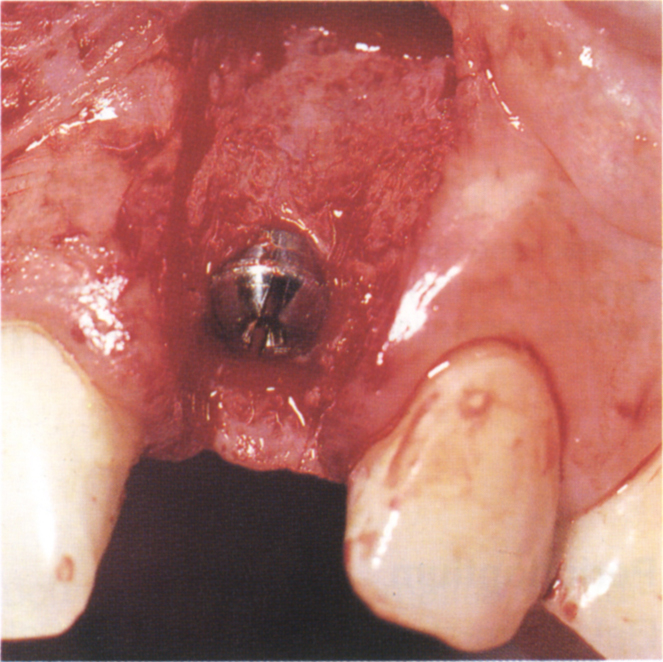
Fig. 33-3d Six months later. The Gore-Tex has been removed. Note the bone deposition.
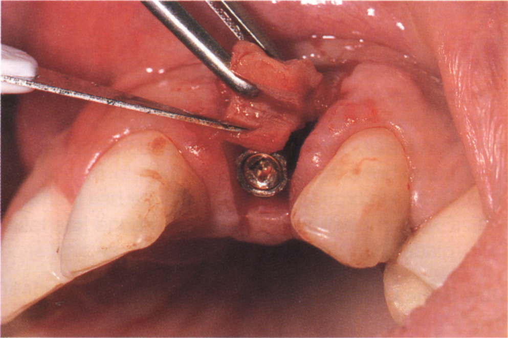
Fig. 33-3e If for aesthetic reasons the soft tissues require augmentation, this can be carried out at abutment connection. The thick palatal flap has been divided vertically, maintainig the apical blood supply to both sections. The inner connective tissue is folded and held in place by a buccal suture passing through both inner and outer sections. This pedicle connective graft ‘plumps’ out the buccal tissue. If the flap were thin and could not be divided, then a free connective tissue graft from, for example the palate, would be required. An immediate temporary crown is made and the tissues sutured around it.
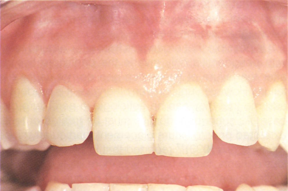
Fig. 33-3f Ten weeks later, the definitive crown is made. Note the contour of the interdental papillae. The apical mucosal greyness is due to an amalgam tattoo resulting from an apical retrograde amalgam placed 12 years prior to extraction of the tooth.
They state that upper and lower jaws of shape groups B. and C., when combined with quality groups 2 or 3, are associated with a favourable prognosis for implants, whereas upper and lower jaws of shape group D or E, especially when combined with quality group 4 make for a poor prognosis. These findings are supported by Friberg et al. (1991)19 who reported that of 4641 fixtures, 69 had failed by the one year follow up. Of these, 13.4% failure occurred in sites of shape D and E compared to 3.9% in shapes A – C. A failure of 19.2% occurred in bone quality 4, compared to 3.9% in quality 1 – 3. In partially edentulous patients, however, van Steenberghe et al. (1990)20 reported a failure of 6% after one year in type 4 bone. Bahat (1993)21 reported a 5.5% failure rate in type 4 bone in the posterior maxilla after periods of between five and 70 months. However, a five year analysis reported that the risk of failure can be as high as 50% in type 4 bone.22 It should be remembered that long-term data on the efficacy of fixture supported bridgework is derived from the treatment of edentulous patients in which fixtures are located primarily in basal bone. The partially dentate patient will usually have fixtures placed in alveolar bone or bone regenerated by surgical techniques. The literature must be carefully followed, so that the patient is given an honest appraisal of the prognosis and so that the most appropriate techniques are used.
Bone Width
At least 4.5 mm of bone bucco-lingually is required for the placement of a 3.75 mm diameter fixture and 6 mm is required for a 5 mm diameter fixture. Nyman et al. (1990)23 reported on the widening of a narrow ridge by the placement of a cell exclusion membrane (Gore-Tex – Gore Co.) on the buccal and lingual aspects of a fixture which was not completely encased with bone at insertion. It is important that the apex of the fixture is firmly embedded in bone, to prevent movement.
Fenestration of a buccal bony plate can be treated by placing an osteoid stimulating space filler, such as autogenous bone chips, over the site which is then covered by a cell exclusion membrane. Provided there is good anchorage of the fixture occlusally and apically, a concave buccal bony plate is not a contraindication for fixture placement24 (Fig 33-3).
If the ridge is to be augmented to increase height and/or width prior to fixture placement (Chapter 22), the following should be borne in mind:
- The augmentation technique should result in bone formation to provide a site for osseointegration. Non-resorbable graft materials should not be used.
- Soft tissue expansion, advancement or grafting will be required to cover the site to be augmented.
- More than one surgical procedure may be required to optimize aesthetics.
- The treatment time may be extended – augmentation will usually require a minimum of six months.
- Fee estimation is difficult since outcome is unpredictable as are the number of procedures required.
- The long-term prognosis for fixtures placed in augmented ridges is unknown. The bone may not be similar to alveolar or basal bone and may represent woven bone. The fixture may not exhibit integration with the new bone117 and the bone may not be well suited to accept occlusal loads.118
Mellonig et al. (1993)25 described the functions of cell exclusion membranes in the augmentation of bone for dental implants as follows:
- ‘They act as a physical barrier, separating the overlying gingival connective tissue from the underlying implant or osseous surface.
- The space created will allow endosseous cells or other appropriate cells to repopulate the area and undergo cell division.
- The physical barrier will act as a second surgical flap, providing protection for the blood clot and stabilizing the wound.
- The wound stabilizing effect will allow mechanical stress acting on the tissue flap to be diverted from blood clot to barrier. Micro movement of up to 10–20 microns during the early stages of would healing is enough to divert the differentiation of mesenchymal cells into fibroblasts, instead of osteoblasts.
- Epithelial migration will be impeded by the barrier.’
Bone Height
The longer the fixture, the less chance there is of failure. Fixtures longer than 10 mm in the mandible and 13 mm in the maxilla have a very good prognosis.26, 20, 27, 17
For standard protocol at least 7.5 mm of bone height is required for a 6 mm long (5 mm diameter) fixture and 8.5 mm for a 7 mm long (3.75 mm or 4 mm diameter) fixture. These are the shortest fixtures available for each diameter. In some situations, such as when the inferior alveolar nerve is in danger of being traumatized and the patient will not accept nerve transpositioning, the standard protocol may require modification. For a 3.75 mm or 4 mm diameter fixture, if a complete countersink is not provided and the fixture is not fully inserted but is stable, it can be placed in less bone height, particularly if cell exclusion membranes are used to augment the height. Fixtures of 5 mm diameter do not have a shoulder for countersinking. Such procedures are applicable to partially edentulous cases in which provisional bridgework is provided, thereby ensuring that the fixture will not be loaded through the mucosa during the integration stage. With short fixtures, however, the outcome is unpredictable as the fixture may not be adequately stabilized. Furthermore, in the posterior mandible, where bone height above the neurovascular bundle is frequently a problem, soft tissue coverage over ridge augmentation is problematic.
It should be acknowledged that the average reduction in height during the first year following tooth extraction has been reported to be 2–3 mm in the maxilla28–29 and 4–5 mm in the mandible.29–30 The successful, early placement of fixtures can prevent this bone loss.
Length of the Edentulous Span and its Relationship to Adjacent Teeth
The peripheries of fixtures should be a minimum of 2 mm and should preferably be 3 mm apart (Figs 33-4a–b). Ideally, a minimum of 14 mm is required between the heights of contour of adjacent teeth to accommodate two 3.75 mm diameter fixtures. The space is occupied as follows:
| Two fixtures – 2 × 3.75 mm | = 7.5 mm |
| 3 mm between the peripheries of the fixtures | = 3.0 mm |
| 1.75 mm between the peripheries of the fixtures and the adjacent tooth × 2 | = 3.5 mm |
| 14.0 mm |
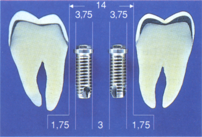
Fig. 33-4a There is 14 mm between the teeth. This is sufficient for placement of 2 × 3.75 mm diameter fixtures.
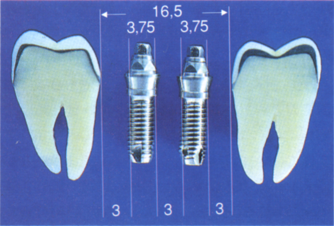
Fig. 33-4b 16.5 mm intertooth space is a more ideal distance. Note that the Estheti-Cone abutments are wider than the fixtures. The distance between tooth and fixture has been increased to 3 mm, compared to 1.75 mm in Figure 33-4a.
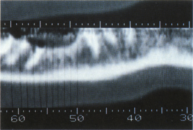
Fig. 33-4c (i) Panoramic view from CT scan. Reformations are perpendicular to the axial cuts. If the fractured distal root of tooth 46 were removed, leaving 47 in situ, a fixture placed in CT section 56 would project onto the crown of 47, since this tooth is tilted.
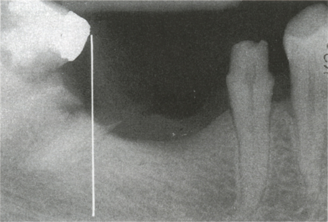
Fig. 33-4c (ii) Periapical view. The vertical line represents section 56. Note that a fixture placed vertically would result in the abutment contacting the mesial surface of tooth 47.
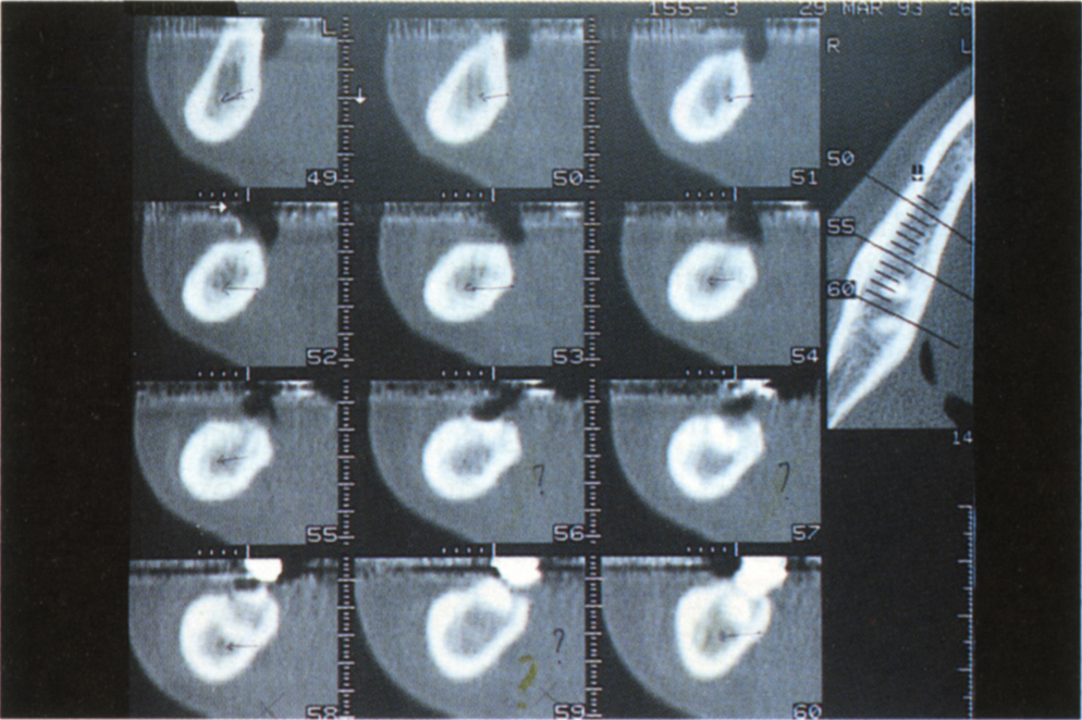
Fig. 33-4c (iii) Reformatted sections do not allow the angulation of tooth 47 to be visualized.
This represents approximately 3.5 mm from the tooth surface to the fixture centre and 7 mm between two fixture centes. It is possible to place two 3.75 mm diameter fixtures in a 13 mm wide space by reducing the distance from the teeth to the peripheries of the fixtures to 1 mm or 1.5 mm and/or reducing the space between the peripheries of the fixtures to between 2 mm and 3 mm. Fixture placement, however, is more difficult, damage to the adjacent teeth is more likely and the resulting restorations are more difficult to maintain. Less than 2 mm of bone between fixtures may result in bone necrosis. When drilling the bone, it is not possible to measure and drill to interfixture or tooth to fixture tolerances of 0.25 mm and, therefore, the closer the space is to the minimal dimensions, the more likely it is that errors will occur. A 16.5 mm intertooth space is more ideal, allowing 3 mm between the fixture peripheries and between tooth surfaces and fixture peripheries.
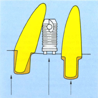
Fig. 33-5a Converging roots reduce the inter-root distance. Parallel copings align two abutments for seating of a provisional bridge. If the copings are used for alignment of the fixtures, this may result in misangulation and damage to the root.
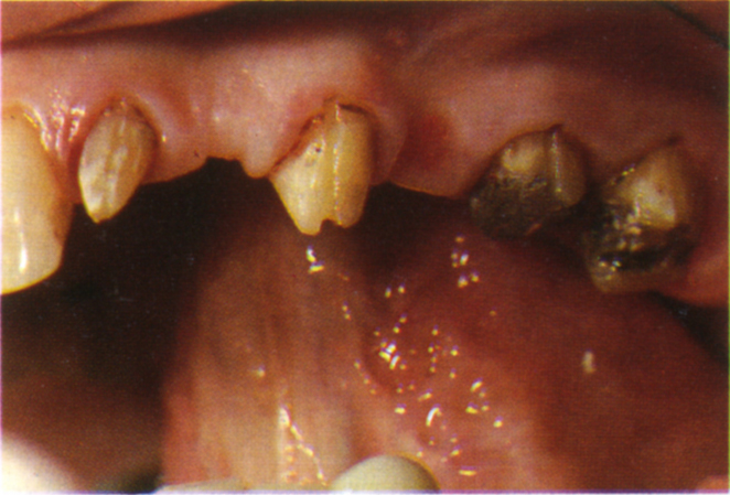
Fig. 33-5b Tooth 22 mesially angulated.
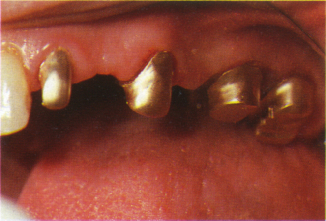
Fig. 33-5c Preparations uprighted on copings.
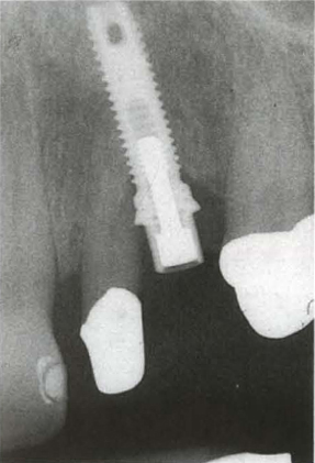
Fig. 33-5d The fixture has been aligned to the coping on 22 and approximates the root.
In the presence of a wide ridge it may be possible to place one fixture towards the buccal aspect and one towards the lingual, so that there is 2–3 mm of interfixture space with a mesiodistal overlap. In such circumstances the intertooth space may be less than 14 mm, yet two fixtures are accommodated.
Two 5 mm diameter fixtures require 2.5 mm of additional space to two 3.75 mm fixtures. Additional fixtures require space to accommodate the diameter of the fixture plus 2 mm, preferably 3 mm space between the peripheries of the fixtures.
In a single 3.75 mm diameter fixture, 6–7 mm of space is required between adjacent teeth.
The intertooth distance should not be assessed solely from reformatted sections of CT scans. Reference must be made to the CT panoramic views and periapical radiographs, as tilted teeth may reduce the apparent space (Figs 33-4c). The tilted relationship can be observed on the panoramic and periapical views, but not on the reformations.
The angulation of the tooth roots must be assessed from radiographs, as converging roots may limit the space available for fixture placement. For example, 7 mm between the amelocemental junctions of two adjacent teeth may reduce greatly if the roots converge (Fig 33-5). If teeth have been uprighted on copings to accommodate provisional bridgework, care must be taken in angulating the fixtures lest roots are damaged (Fig 33-5).
These guidelines can be reduced but the closer the fixtures are placed to adjacent teeth, the more likely that the root will be damaged or misangulation will occur, due to instrument impingement. The abutments to fit 3.75 mm, 4 mm or 5 mm diameter fixtures for the Nobelpharma system are either 4.5 mm (standard abutment) or 4.8 mm (Cera One, EsthetiCone) in diameter (Fig 33-6). A 3.75 mm diameter fixture, placed with its threads 1 mm from an adjacent tooth will have 0.475 clearance between the tooth and an EsthetiCone abutment. This may compromise embrasure form. Two fixtures placed with their threads 1 mm apart, (fixture centres 4.75 mm apart for 3.75 mm diameter fixtures), would not allow sufficient space for EsthetiCone abutments and only 0.25 mm clearance for standard abutments.
Curve of the Edentulous Span
Fixtures placed in a line will be loaded less favourably than those placed around a curve.31
Relationship of the Proposed Fixture Sites to Vital Structures (Fig 33-7a)
Gunne et al. (1991)32 reported that, following fixture placement in the posterior mandible, 39% of sites exhibited sensory disturbance initially, reducing to 19% at two years with only a small further reduction at three years. Henry et al. (1993)17 reported a 4% incidence of paraesthesia at three years and Ellies (1992)33 reported a 13% incidence, lasting from one to four years. This constitutes a high risk of nerve damage and patients should be warned of this possibility.
The dimensions of residual bone in relation to the inferior alveolar canal, the mental foramen, the maxillary sinuses and the floor of the nose must be evaluated. CT scans with reformatted views may be used (Figs 33-7; 33-9–10). In the Brånemark system, it is necessary to have a minimum of 7.5 mm of usable bone occlusal to the inferior alveolar canal for the placement of a 6 mm (5 mm diameter) fixture. For a 7 mm fixture, 8.5 mm of usable bone is required (3.75 mm or 4 mm diameter). It is sensible to assume that there is 2 mm less height available than that measured from the CT scan.
Provided there is adequate cortical plate in which to stabilize a fixture, it is possible to lift the floor of the antrum and nose and for bone to form around the fixture. Bone grafts placed between the alveolus and antral lining34 and/or occlusal to the alveolus35 can be used to stabilize fixtures and to promote osteogenesis. A fixture surface should be no closer than 3 mm to the anterior wall of the mental foramen, or the anterior margin of a loop of the inferior alveolar canal anterior to the foramen. It is imperative that the dimensions are assessed prior to surgery.
In cases where there is severe resorption, techniques for lateral transpositioning of the inferior alveolar nerve have been described. In one report of 10 patients,36 normal function had returned in all patients 12 months after surgery. In another report of 10 procedures, two patients had unilateral mild sensory disturbance which resolved in three weeks, the others displayed no such symptoms.37
The risk of morbidity must be related to the skill and experience of the surgeon.
Relationship of Fixture Sites to the Opposing Jaw (Fig 33-7b and c)
There must be enough space between the jaws to allow for: a minimum of 1.5 mm–2 mm of a standard abutment over the soft tissue in the mandible and 0.5 mm in the maxilla; the overlying gold cylinder, which is either 3 mm or 4 mm high; the prosthesis. If a conventional 3 mm abutment will be used, the minimum space required to accommodate the abutment and gold cylinder between the top of the fixture and the opposing occlusal surface is 6–7 mm. Ideally, this space should be 10 mm, to accommodate the occlusal restoration. An EsthetiCone abutment with a 1 mm collar and overlying gold cylinder requires 6.7 mm space from the top of the fixture to the opposing dentition, to accommodate the abutment and overlying gold cylinder to which must be added the occlusal restoration. Deep overbites may present difficult space and angulation problems and must be carefully analysed.
There must also be sufficient access for the handpiece during fixture placement. The latter may be severely restricted if overerupted teeth or overlong fixed bridgework are retained in one arch.
The angulation of bone and bucco-lingual relationship to the opposing jaw influences the fixture angulation, and may preclude ideal fixture location relative to the opposing jaw. Although corrections can be made with angulated abutments or ridge augmentation, the more favourable the opposing relationships, the easier treatment can be carried out (Figs 33-7c–h, 33-16f [viii]). In the maxilla, the buccal plate of bone resorbs more rapidly than the palatal plate, whereas in the mandible, the lingual plate resorbs more rapidly than the buccal plate. The greater the resorption, which is a function of: the patient’s metabolism; the amount of prior bone loss due to periodontal disease; the amount of bone loss due to surgical trauma; the period of time since extraction; the loading of the bone by a denture, the greater the disparity between the arches will be.38 To prevent overloading the retaining screw, the prosthesis should not extend laterally by more than the diameter of a fixture in the molar region, or twice the diameter in the incisor region.31
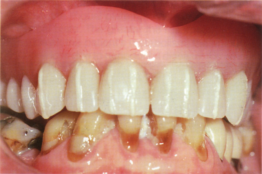
Fig. 33-7b (i) Radiopaque markers (barium sulphate) sealed to the patient’s denture with a light curing resin (Palaseal – see Appendix).
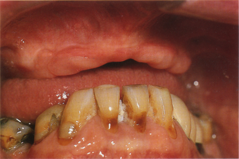
Fig. 33-7b (ii) Note the adverse mandibulo maxillary relationship.
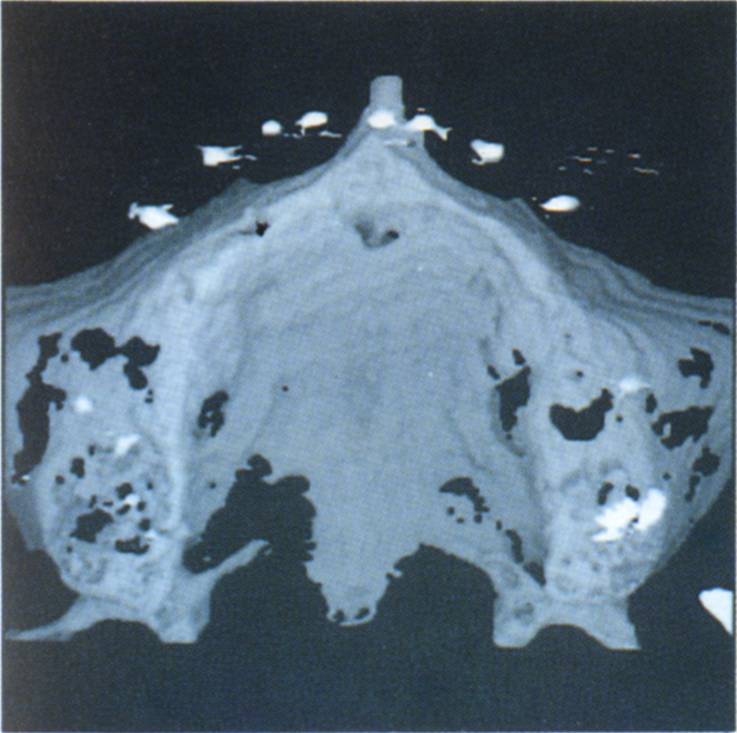
Fig. 33-7c (i) 3-D reformation shows the positions of the teeth relative to the alveolus.
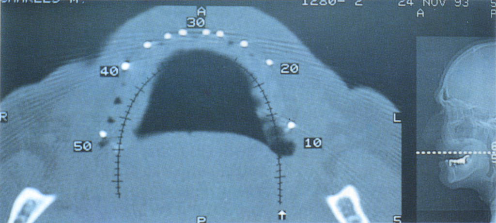
Fig. 33-7c (ii) Axial CT cut.
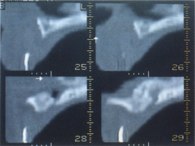
Fig. 33-7c (iii) Reformatted views show the need to position the teeth buccal to the alveolus. An overdenture is the treatment of choice.
Fixtures should ideally be aligned parallel, or almost parallel (a mesio-distal convergence of approximately 10° assists in the development of a natural looking ‘interdental papilla’24) and in the correct bucco-lingual position.
Relationship of the Proposed Fixture Sites to the Anticipated Position of the Replacement Tooth (Figs 33-7d to j)
The relationship of the remaining bone to the anticipated tooth position determines the feasability of a fixture supported replacement. For example, in the maxilla, buccal plate resorption or loss of bone through trauma may result in an edentulous area being palatally placed relative to the adjacent teeth. Without ridge augmentation, the position of the fixture retained restoration may be aesthetically unacceptable, unless an overdenture is provided.
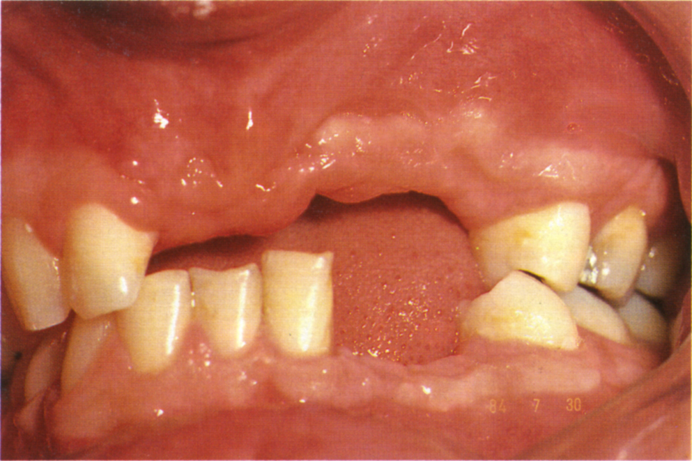
Fig. 33-7d Edentulous area following road traffic accident.
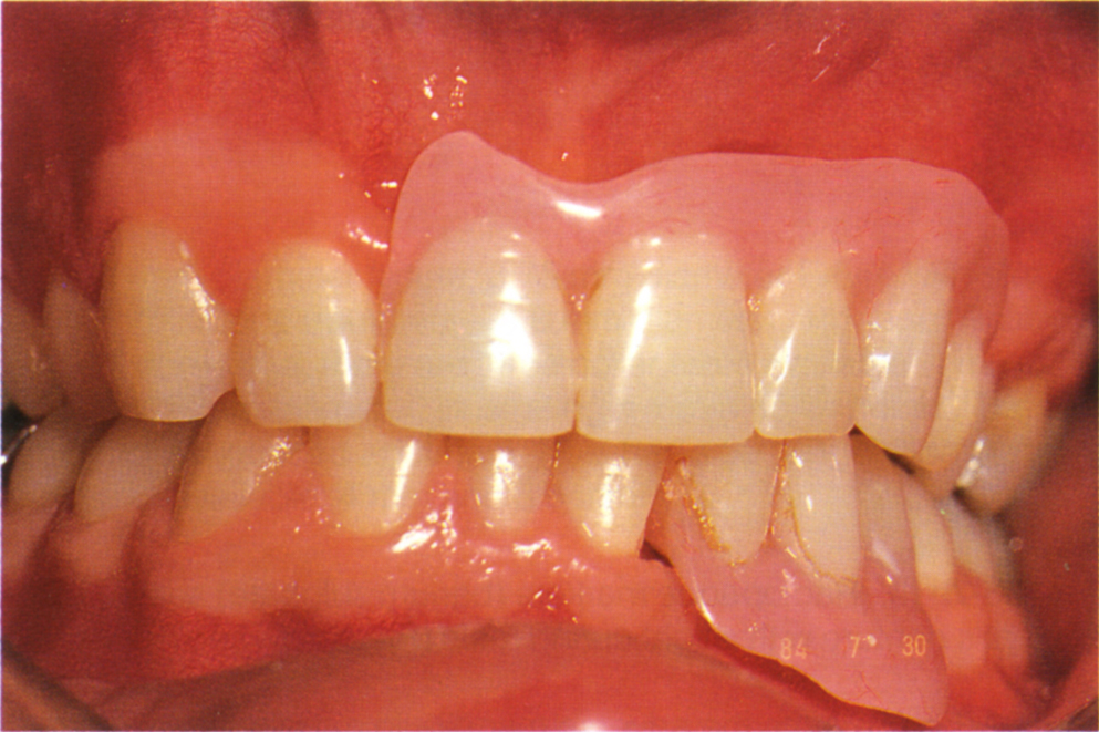
Fig. 33-7e Tooth try-in.
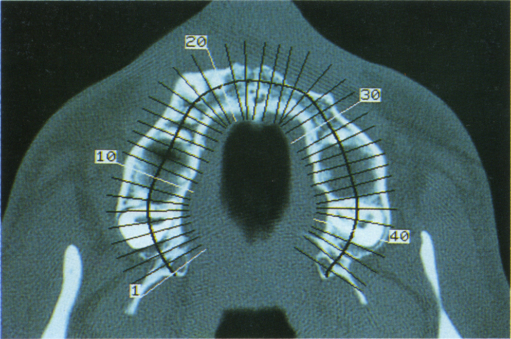
Fig. 33-7f Axial cut CT scan. There is a wide alveolus, adequate for placement of fixtures.
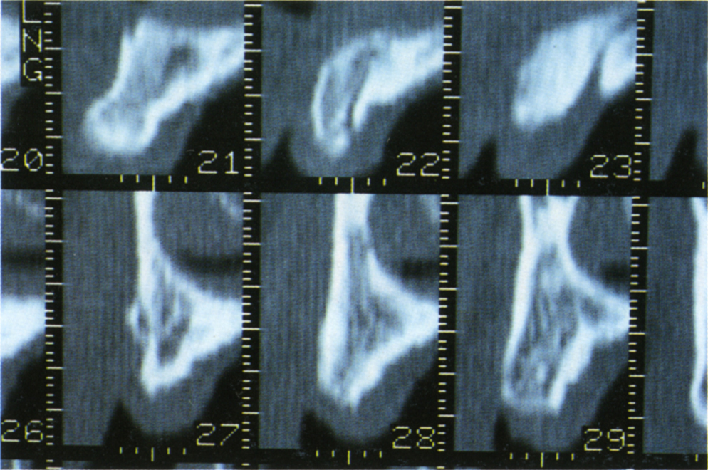
Fig. 33-7g Reformatted sections perpendicular to the axial cut, corresponding to marks 21–23, 27–29 on the axial cut. These marks are 2 mm apart. There is adequate bone height for fixtures at sites 21, 23, 27, 28, 29, but see Figure 33-7e.
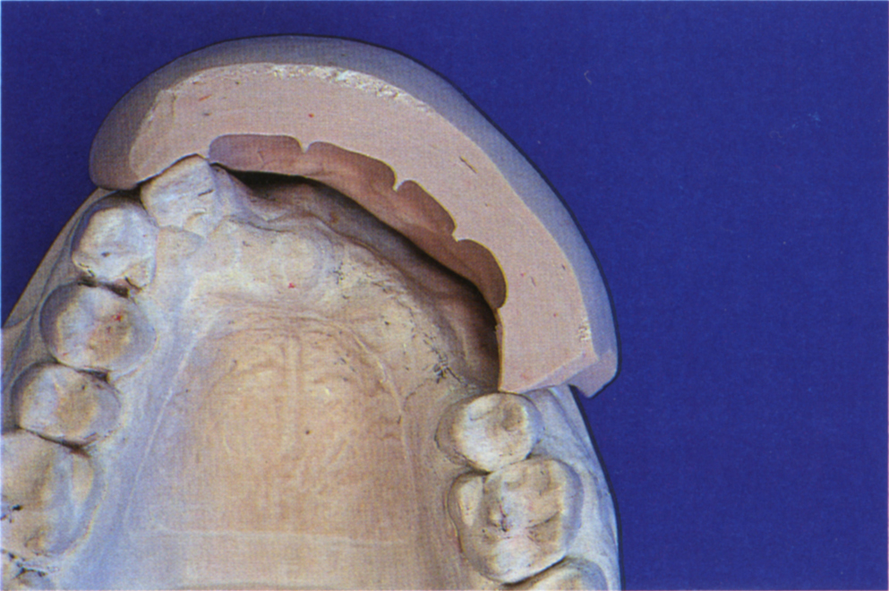
Fig. 33-7h Labial index made to the tooth try-in and positioned on the cast. Note that the tooth position is considerably labial to the edentulous alveolus. Vertical placement of fixtures into the alveolus would create a large horizontal discrepancy between the fixtures and the teeth. This, in addition to the need for the replacement of gingivae, indicates use of an overdenture, unless bone grafting techniques are used. Labial inclination of the fixtures would require uprighting with angulated abutments, otherwise the screws would exit through the labial surfaces of the teeth. The angulated abutments would not load the fixtures axially. Careful analysis of the CT scans, the patient and study casts is essential.
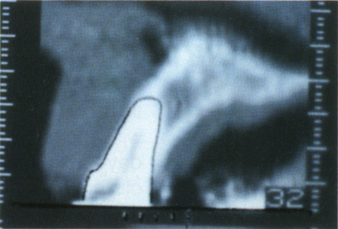
Fig. 33-7i Outline of tooth 21 (section 32) drawn on a tracing paper overlay. Note the markers at the base of the section have been drawn (different patient from Figs 33-7a to e).
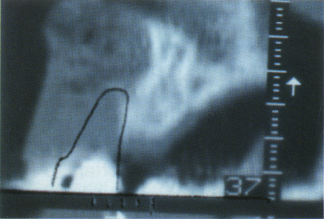
Fig. 33-7j Overlay from section 32 positioned over section 37 and orientated by the markers and the bottom of the section. This reveals that the replacement tooth must be positioned considerably anterior to the ridge. Computerized programmes are available to do this (SIM/Plant – Columbia Sc. Inc.), but the clinician may not always have access to them.
Smile Line
A patient with a ‘smile line’ or functional lip line which does not expose the gingivae (Fig 33-19a), presents fewer aesthetic difficulties than the patient with a smile line in which conventional abutments would show (Fig 33-19c). Tapered abutments (EsthetiCone – Nobelpharma) overcome the aesthetic problem of unsightly abutments by positioning margins submucosally. However, long-term clinical studies are required to establish whether the mucosal margin will, with the passage of time, retract, thereby exposing the abutment margin.
Facial Aesthetics
The existing failed restorations may support the facial soft tissues through buccal flanges on removable prostheses. Conversion to a fixture-retained, fixed prosthesis may produce disappointing facial aesthetics – overdentures or removable gingival facades (epithesis) should be considered in such situations. Provided that a space is allowed for adequate oral hygiene, it is sometimes possible to provide a fixed cantilevered gingival facade as part of a fixed prosthesis.
Phonetics
Fixtures are narrower than teeth. This, combined with bone loss and a fixed prosthesis with space between its undersurface and the mucosa, can create spaces which produce phonetic difficulties (Fig 33-16f). This possibility must be assessed prior to designing the definitive restoration and the use of a removable appliance to close the embrasures must be considered. Furthermore, lack of ideal positioning of the fixtures may lead to bucco-lingual enlargement of the prosthesis or incorrect tooth positioning, further compromising phonetics.
The Transition from Failed Restorations to Fixture Supported Restorations
The options for the transition stages, from the failed restorations to fixture supported restorations are:
- No transitional restoration
- Removable transitional restoration
- Fixed transitional restoration
The options must be discussed with the patient as the sequence length and associated cost of treatment may vary substantially, depending upon which option is adopted.
Three situations require consideration:
(i) When the Patient is Rendered Edentulous Prior to Fixture Placement
In this situation it is important to ensure that the transitional denture does not transmit load to the underlying fixtures, nor traumatize the overlying mucosa. Denture stomatitis must be treated with anti-fungal agents and if there is no response, the blood analysed for differential white cell count, haemoglobin level, iron binding capacity and total serum iron. Attention must be paid to the fit and occlusion of the denture.
If a sufficient number of additional fixtures can be inserted and sacrificed subsequently, then these can be connected at the time of insertion and used to support a provisional bridge. Therefore, the remaining fixtures will not be loaded during the integration stage and the patient has a fixed restoration. The efficacy of such treatment requires assessment by controlled clinical studies.
(ii) When Some Teeth Remain and there is no Periodontitis
The transition from the failed restoration to the fixture supported restoration can be through fixed or removable prostheses. Regular hygienist appointments are advisable at two monthly intervals to check the oral hygiene status and carry out root debridement, if necessary, to maintain the healthy periodontal status. Teeth which exhibit periapical radiolucencies or symptoms of pulpal inflammation or necrosis, which are in the quadrant in which fixtures are to be placed, must be treated endodontically prior to fixture surgery. If such teeth are to be retained only during the transition stage, to support a provisional restoration and then extracted, they can be treated by canal debridement, preparation and calcium hydroxide dressing, final obturation is not required.10–11 If they are to be retained, final obturation is required. Periapical inflammation must be resolved prior to fixture surgery.
(iii) When Some Teeth Remain and there is Periodontitis
The transition is difficult, as the patient may not be motivated to control disease, yet there is a risk of transfer of organisms from the teeth to the fixtures (see page 493). It was reported, in a three year prospective study, that the highest incidence of fixture failures occurred in patients with a relatively high plaque index before fixture placement.17 Hygienist appointments at one monthly intervals must be adhered too. Chlorhexidine mouthwash (0.2%) should be used twice daily. In the absence of a satisfactory response in a patient with refractory periodontitis, doxycycline 200 mg initially, and then 100 mg each day should be administered for three weeks.39 Further recurrence should be treated with metronidazole 250 mg every eight hours for 10 days.40 It is essential that neither the patient nor the clinician are lulled into a false sense of security, and think that the fixtures will resolve the problems, whilst retaining teeth with periodontitis.
If the patient’s compliance deteriorates, leading to failure of the provisional bridge abutments it may, in the presence of a sufficient number of fixtures, be possible to expose some fixtures early, connect abutments and use these to support the provisional bridge and thus prevent transmucosal loading of the remaining fixtures. There is a real risk of failure in the fixtures supporting the provisional bridge.
Endodontic considerations are as in (ii) above.
Keratinization of the Mucosa Around the Fixtures
Data from edentulous patients restored with fixture supported prostheses indicate that the presence of keratinized tissue around the fixtures is not necessary for long-term success,40–44 although local soft tissue lesions and discomfort may occur. However, a three year study of partially edentulous patients restored with a combination of fixtures and natural abutments reported that no failures occurred around fixtures with attached ‘gingivae’ both bucally and lingually (17 fixtures), whilst seven failures occurred in 48 fixtures with partially or no attached gingivae.32 Until proven otherwise, it would seem prudent to ensure that attached tissue is present around fixtures in tooth/fixture supported bridges.
Maintenance
Following the completion of treatment, a maintenance prescription must be made. The details depend upon whether or not teeth remain, the patient’s compliance and whether or not periodontitis remains or reoccurs (see page 529).
Factors Related to the Biomechanics of Fixture Supported Prostheses
- Whether to join fixtures to teeth
- Framework design and choice of materials
- Occlusion and the choice of materials for the occlusal surfaces
- Choice of articulator
Whether to Join Fixtures to Teeth
Construction, fitting, maintenance and retrievability are all simplified if the fixture supported section is independent of the teeth. However, this is not always possible since: teeth may be retained between the fixtures; it may be possible to place only one fixture, so that connection to an adjacent tooth is necessary if a bridge is to be constructed; a tooth may require stabilization by connection to the rigid fixture supported section.
The possible advantages of connecting the teeth to fixtures are: additional support to convert a cantilever design to a fixture and tooth supported design; the proprioception from natural teeth may limit the load applied to fixtures. However teeth incorporated between fixtures will be subjected to different stresses than teeth at the end of bridge spans and may not be loaded sufficiently to provide proprioceptive feedback.
Partial or complete loss of periodontal ligament receptors in a patient with an osseointegrated fixture supported prosthesis in one or both jaws, results in an interocclusal detection and discrimination threshold which is approximately 2 × – for fixtures against teeth, to 3 × – for fixtures against fixtures, that of opposing natural teeth.45 Furthermore, the low loads, that can be detected when applied to teeth cannot be detected when applied to fixtures.46
Preliminary data32, 47, 48 indicate a favourable response to the connection of teeth to fixtures, however, many parameters have not been tested, such as the affect of: tooth mobility; vital or root filled teeth, since a higher load will be applied to a non-vital tooth before there is patient awareness;49 length of the span; number of teeth incorporated; number of fixtures incorporated; length of fixtures; distance between fixtures; distance between teeth; type of teeth, that is, molars, premolars, canines, incisors; the maxilla versus the mandible; occlusal load, that is, a patient with large well developed muscles of mastication versus a frail patient with small musculature. The current data must be interpreted cautiously and the clinician must keep abreast of the literature. The following points should be considered when deciding whether or not to join teeth to fixtures.
Simplicity of Construction
Construction is simplified if the fixture supported section is independent of the teeth. Linkage requires passivity of fit, not only between the superstructure and the fixture abutments, but also between the superstructure and teeth. Long span ceramo-metal reconstructions will require post-ceramic soldering to obtain this passivity of fit (see page 203).
Retrievability
An advantage of fixture supported prostheses is the ease of retrievability, should a problem develop. Linkage to teeth complicates the design and clinical procedures associated with retrievability.
Cantilever Extension
Assuming a maximal occlusal force of 300 N in the molar region, which is comparable to the forces reported by Falk et al., 1989;50 Carlson, 1985;51 Haraldson, 1988;52 Carr, 1987;53 Haraldson, 1979;54 Hobkirk, 1992.55 Rangert et al. (1989)31 calculated that to avoid fracture of the retaining gold screw, which has an ultimate tensile strength of approximately 600 N, posterior fixture supported cantilevers should not extend more than 2 × the inter-fixture distance (Fig 33-8c [i]). However, lateral forces on cantilevers will produce bending moments about the distal fixture. In the presence of five or six fixtures positioned around the arch, the bending moment at the distal fixture will be resisted adequately by the other fixtures. In the presence of only two fixtures in a line, the bending moments will not be resisted adequately and may result in the failure of the gold screw, which has a flexural fatigue strength of 50 to 60 Nc.56 A 50 N lateral force applied 20 mm from the fixture, producing a bending moment of 100 Ncm, would exceed the fatigue strength. Three fixtures reduce the bending moment more efficiently than two. To reduce lateral loading, posterior disclusion should be provided and in the presence of only two fixtures, the cantilever extension may be limited to the interfixture distance or less.
Rangert et al. (1989)31 suggested a maximum posterior cantilever extension of 20 mm in the mandible when using four or five 10 mm fixtures, however, in the maxilla, in which the bone is less dense, a maximum of 10 mm cantilever extension is recommended with five or six 10 mm fixtures.
In the incisal region, with a maximum occlusal force of approximately 150 N, the cantilever can extend 4 × the inter-fixture distance, provided that there are fixtures positioned around the arch to resist transverse loading. Two fixtures in a line could resist axial load on the cantilever, but not transverse loading. In such circumstances, the cantilever must be reduced or preferably eliminated, since anterior contacts in excursions will be present if anterior guidance is provided.
Flexibility of the Abutment Complex
The axial movement of a non-pathologically mobile tooth in its socket is less than 100 microns when subjected to a bite force of up to 20 N.57–59 There is a rapid axial displacement with loads of up to 10 N and then the displacement reduces to reach a maximum, at approximately 20 N, with a mean of 31 microns (SD ± 13.56) for a maxillary first molar.57 Rangert et al. (1991)60 reported that, when subjectd to loads of 25 N and 50 N, rigid cantilevers of 8 mm or 16 mm connected to either a 4 mm or 7 mm high abutment, flexed more than 100 microns at their most distal ends (Fig 33-8). This implies that a tooth attached to the end of a single unit cantilever would be subjected to axial loading as a result of abutment flexure. This would limit the displacement of the bridge so that the gold screw would not have its tensile fatigue strength exceeded. Furthermore, this does not take into account flexibility of the bone around the fixture. This was reported by Sekine et al. (1986)59 to be between 17 and 66 microns with a 20 N load and would increase the movement produced at the abutment and hence, at the end of the cantilever.
The abutment flexure described above relates to standard abutments, but it is probable that similar flexure occurs with EsthetiCone abutments, since these are fabricated from the same material and have similar cross sectional dimensions at the level of the gold cylinder margin.56
The rotational movement between the gold cylinder and the abutment is approximately 10 microns, giving rise to a movement of approximately 100 microns at a point 16 mm from the abutment.60 This can be resisted by a clinically non-mobile tooth rigidly attached to the fixture by a bridge. Repeated 50 micron transverse motion at the end of a 16 mm cantilever will give rise to gold screw preload reduction. Repeated transverse motion in excess of 100 microns will result in screw loosening.60
The Following Points should be Considered Prior to Deciding Whether to Join Teeth to Fixtures and if so, How to Make the Connection (see Figs 33-8 + 33-20–21)
- The further the tooth is from the fixture, the less flexure is required of the abutment to accommodate the displacement of the tooth (Fig 33-8a). The closer the tooth, the greater the flexure required and the less likely the tooth is to share the load. However, axial loading of a tooth with clinically normal mobility positioned 8 mm from the fixture, will not overstress the gold screw.
- The greater the mobility of the tooth, the more the abutment would need to flex for the tooth to be loaded. The findings of Rangert et al. (1991)60 relate to normal tooth mobility patterns (Fig 33-8b).
- If the tooth did not share the load, then the further the point of force application from the fixture, the greater the bending moment on the abutment (force × distance from fulcrum) (Fig 33-8c).
- If two or more fixtures are connected, the one closest to the pontic is subjected primarily to compressive stress, and the more remote ones are subjected to tensile stress (Fig 33-8c). The mechanics related to flexion of the abutment, change, and the bridge should, for design purposes, be considered as a cantilever extension (Figs 33-21l, s, t).
- A molar tooth with clinically normal mobility will resist lateral rotations about a single fixture, so that the fatigue strength of the gold screw is not exceeded.
- If two fixtures are connected and cantilevers provided, lateral forces on the cantilevers will produce a bending moment in the distal abutment which may exceed the fatigue strength of the gold screw (Figs 33-8c [ii] [iii]).
- A posterior cantilever can extend twice the interfixture distance and an anterior cantilever four times the interfixture distance, but the effect of transverse forces must be considered and the cantilever modified accordingly.
- An attachment in the mesial aspect of a distal molar will allow the tooth to be intruded under axial load, thereby shortening the cantilever effect on the fixtures (Fig 33-8c [iv]). Permanent depression of the tooth section relative to the fixture supported section may occur.61–62
- If two fixtures are connected, an attachment placed in a tooth with normal mobility may resist lateral torquing of the abutment when transverse forces are applied to the pontic (Fig 33-8c [iv]). However, the level of tooth mobility at which this resistance no longer occurs such that a bending moment develops which exceeds the gold screw strength, is unknown. Furthermore, lateral forces on the tooth will result in engagement of the attachment, so that the tooth extends the cantilever in the horizontal plane.
- Reduction of the oclusal contacts in lateral excursions, that is posterior dislusion, will reduce lateral forces.
- Reduction of intercuspal occlusal contacts by 100 microns at the distal end of a cantilever will significantly reduce the bending moment at the distal fixture.63
- Reduction of the length of cantilever extension will reduce the bending moment at the fixture.
- Placement of a cylindrical slide attachment distal to the fixture, with the matrix attached to the gold cylinder (Fig 33-8c [v]), may allow a connected tooth to move laterally under transverse load and thus not produce a bending moment at the fixture. However, this assumes that the rotation of the tooth is along an arc with a rotation center in the attachment. This is unlikely to be the case, particularly since the tooth would tend to rotate lingually and apically and not purely in a horizontal plane. Any binding of the attachment resulting from dissimilar rotations will lead to lateral force application to the fixture abutment and/or wear of the attachment. Such wear may result in the pontic, which extends from the tooth, acting as a cantilever and cause an unacceptable increase in tooth mobility. In a maxillary bridge, the worn attachment may allow the pontic to move occlusally when the teeth are unopposed. Furthermore, this design complicates retrievability, as the crown on the tooth would need to be screw retained.
- Since the mandible flexes,64–65 posterior mandibular fixtures should not be joined to either teeth or fixtures on the opposite side of the mandible (Figs 33-21v–z). If a joint is required, an attachment should be used to allow some movement to occur.
- When joining teeth to more than one fixture, it is preferable for the tooth borne section to be capable of supporting the units extending from it, independent of support provided by the fixtures and vice-versa. This may not always be possible.
- It is unlikely that teeth which act as pier abutments between fixtures are subjected to functional loading unless they are considerably remote from the fixtures, or form the anterior section of a curved bridge, for example, fixtures in sites 14, 13, 12, 24, 25, teeth 11, 21, 22, 23 (Fig 33-20). In such circumstances, flexure of the abutments, bone and framework may result in loading of the teeth.
- Intramobile elements are not manufactured for the Brånemark system. Based on the above, they may be an unnecessary design complication. Furthermore, if designed to accommodate excessive tooth mobility, how is the flexure of the element calculated for each situation? How frequently do such elements require changing? Such elements however, may facilitate energy absorption under occlusal load and thereby reduce energy transmission to linked teeth. This may prevent the intrusion that is sometimes observed in these teeth.
- The data on the clinical response to combinations of fixtures and teeth32, 47–48 apply to single fixtures connected to single teeth, primarily over three-unit bridge spans in the mandible. Although the prognosis in such situations is excellent, extrapolation to other situations should be cautious.
- The length of the fixtures may influence clinical decisions, since failure decreases with increased length.
Methods of Joining Fixtures to Teeth
i) With telescopic castings over copings on the natural teeth, to make the bridge retrievable (Fig 33-20): If the fixture bridge and the telescopic coverings are fabricated as one casting, the copings should be cemented to the teeth prior to making the final impression. In the presence of non-mobile teeth, cement inside the telescopic units would prevent complete seating of the fixture bridge on the abutments and it is, therefore, omitted from the interior of the telescopes. An alternative and preferable procedure is to temporarily cement the telescopic units over the cemented copings and then make a soldering index to link them to the framework of the fixture-retained bridgework (Figs 33-20k–r).
ii) By rigid attachments (Figs 33-8c, 33-20l–o, 33-21s–u). Here the matrix may be placed in the natural abutment or distal to the fixture abutment (Figs 33-8c [iv] [v]).
iii) With screw joints. Attachments are provided as above, and a horizontal screw is incorporated to rigidly join the components.
iv) Resilient components are incorporated beneath the implant supported section, to allow movement to occur. The need for and efficacy of such devices requires verification by controlled clinical studies. Such devices are not available for the Brånemark system.
Framework Design and the Choice of Materials
The framework should be rigid and, therefore, materials with a high modulus of elasticity such as high palladium alloys (Palliag M – Degussa) are indicated. Although in this respect, non-precious metal alloys such as cobalt chromium are suitable, casting difficulties may make provision of passivity of the framework against the abutments unpredictable. Furthermore, errors are not readily corrected by soldering and there is a risk of contamination of the titanium implant components by the non-precious alloy.
There is a high probability of framework distortion occuring during the firing of porcelain for ceramo-metal restorations (see page 196), particularly when firing four or more units which are not in a line. A protocol which routinely includes post-ceramic soldering reduces the risk of fitting a non-passive framework, see page 203 and Appendix for the soldering procedure (Fig 9-14b). Gold alloys are easier to solder than non-precious alloys and produce good joints more predictably, hence these are used for ceramo-metal restorations (Degudent Universal – Degussa).
It must be stressed, however, that in resin covered bridges, one-piece castings are made and these are only sectioned and soldered if there is doubt about the passivity of fit following checking with only one distal abutment gold screw in place, initially on the working cast using 20 × magnification and then in the mouth using 2 × magnification. Similarly, short (two to three units) ceramo-metal restorations which do not pass around a curve are cast as one piece. For longer ceramo-metal spans, or where the framework passes around a curve, or in cases in which teeth are joined to fixtures, post-ceramic soldering is used to join the components. It is possible that in the future, titanium will be chosen for frameworks (Procera – Nobelpharma).
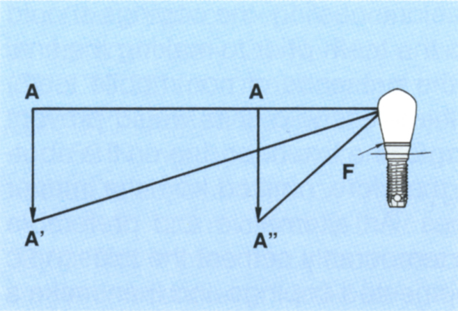
Fig. 33-8a (i) Distance A–A’ is the same as A–A”. However, since A–A’ is further from the fixture (F = axis of rotation), less flexure of the abutment is required to accommodate the movement.
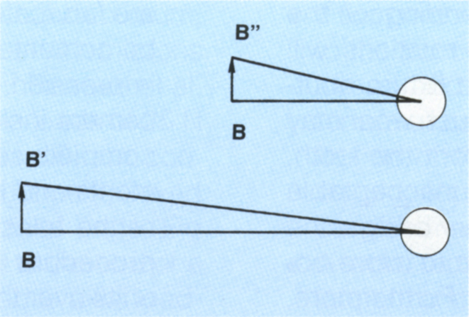
Fig. 33-8a (ii) Occlusal view. Since B–B’ is further from the fixture than B–B”, less horizontal rotation is required to accommodate similar dimensions of movement. A molar tooth with normal mobility connected to the bridge at B will resist lateral rotations around the fixture, so that the fatigue strength of the gold screw will not be exceeded.
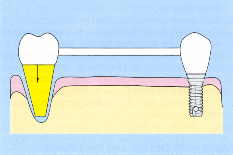
Fig. 33-8b (i) Assuming movement of less than 100 microns when the tooth is loaded, flexure of the abutment allows the tooth to accept the load, thereby limiting the flexure of the fixture abutment. Neither the tensile nor fatigue strength of the gold screw are exceeded.
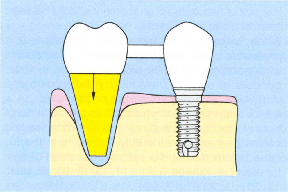
Fig. 33-8b (ii) The tooth is closer to the fixture than in 33-8b (i), therefore, more flexure of the abutment is required to accommodate the tooth movement. However, an 8 mm span with less than 100 microns axial tooth movement will not overstress the gold screw.
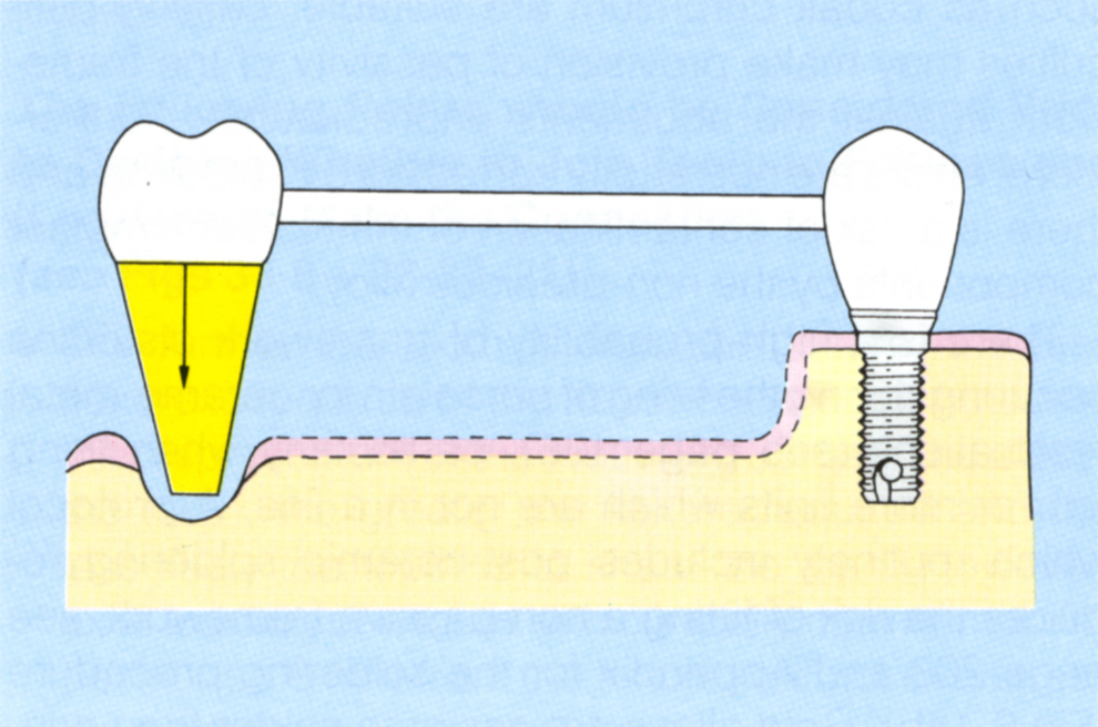
Fig. 33-8b (iii) With greater mobility of the tooth, the abutment must flex more than in Figure 33-8b (i). In order for the tooth to accept the load, the abutment must flex further. The greater the length of the span, the less flexure required, but in the event of the tooth not accepting the load, the greater the bending moment on the abutment.
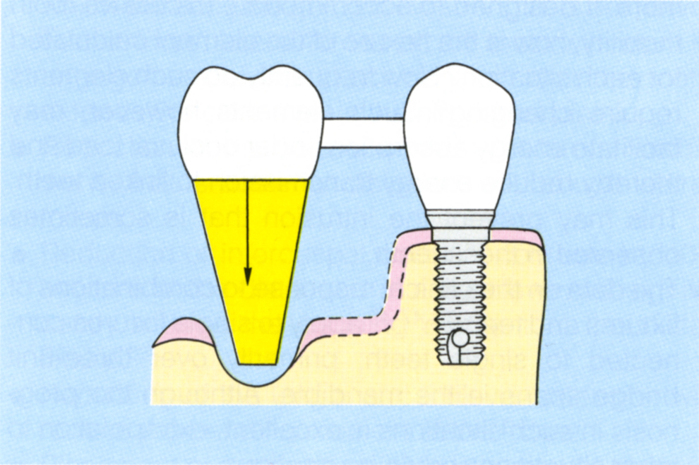
Fig. 33-8b (iv) A very mobile tooth close to a fixture requires more flexure of the abutment than in 33-8b (i), (ii) or (iii) and acts as a cantilever.
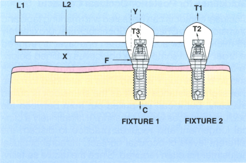
Fig. 33-8c (i) If fixture 2 is absent, rotation occurs about axis F. The tensile stress on screw T3 equals

when loaded at L1. The smaller X, the less the stress. When both fixtures are present, provided T3 is pre-stressed, loading of the cantilever applies a compressive stress on fixture 1 (C) and a tensile stress on fixture 2 (T1), stressing the screw T2. For posterior cantilevers, maximum length = 2x the distance between fixtures 1 and 2. For anterior cantilevers, maximum length = 4x the distance between fixtures 1 and 2.
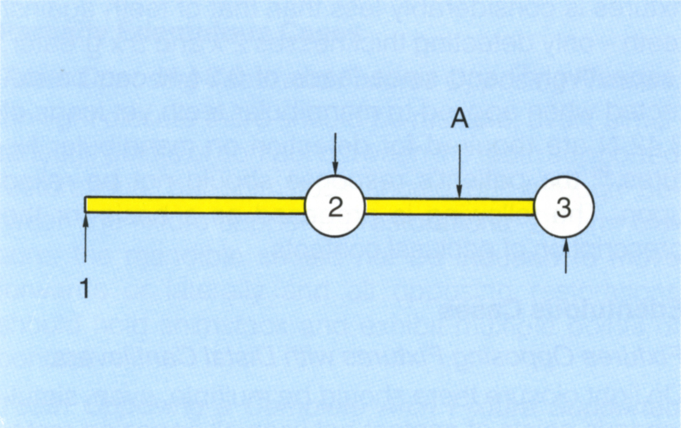
Fig. 33-8c (ii) Occlusal view of 2 fixtures with a cantilever extension. A lingual transverse force applied at 1 displaces the abutment 2 lingually. This is resisted by the bone around the fixture and produces a buccally directed force on the bridge. Abutment 3 is displaced buccally, producing a lingually directed force on the bridge (A = axis of rotation).
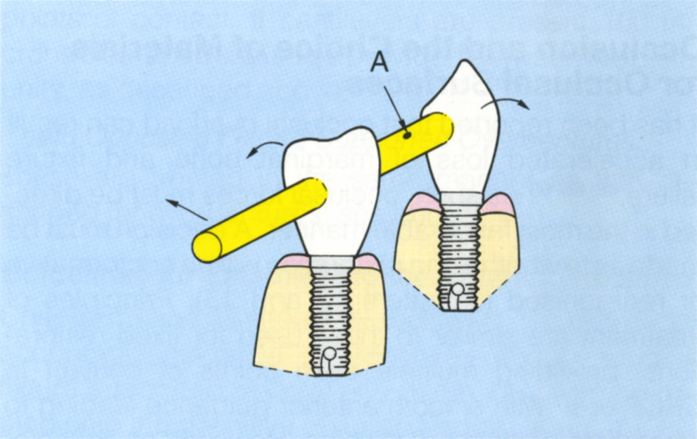
Fig. 33-8c (iii) Two fixtures with a cantilever extension, as in Figure 33-8c (ii). The transverse force on the cantilever produces a bending moment at the abutment, rotating about an axis (A) located somewhere between the two fixtures. The resultant on the abutments is not purely in the transverse plane, but includes a rotational component.
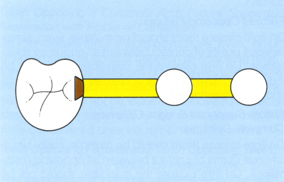
Fig. 33-8c (iv) Two fixtures connected to a tooth. A dovetail attachment positioned in the mesial aspect of the tooth. Under axial load the tooth can intrude and not extend the pontic length which is twice the interfixture distance. Transverse load on the pontics may be resisted by the tooth, although this cannot be assured. Transverse load on the tooth will extend the cantilever from the fixtures. The distal pontic must be relieved from the occlusion by 100 microns and all posterior units must disclude on excursive movements, under both light and heavy muscle load. There is the possibility that the tooth will intrude, moving out of the attachment.
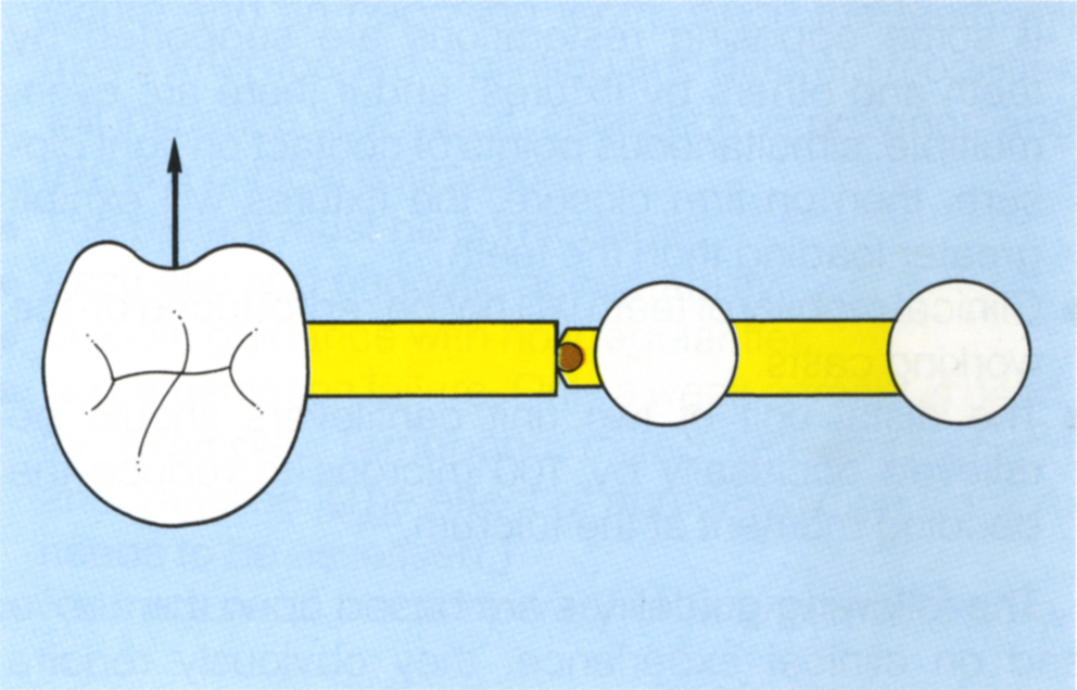
Fig. 33-8c (v) A slide attachment positioned close to the fixtures. Axial load on the tooth will not be stress broken and will extend the cantilever from the fixtures to more than twice the interfixture distance. Transverse loads may be stress broken by rotation around the attachment. However, the tooth will not move purely horizontally and the attachment may therefore engage and load the fixtures.
Occlusion and the Choice of Materials for Occlusal Surfaces
It has been reported that occlusal overload can result in accelerated loss of marginal bone and fixture failure.48, 68–69 As such, occlusal forces must be directed in the most favourable manner. A decision must be made as to whether the restoration will be conformative or reorganised (Chapters 12 and 13). Principles of treatment are similar to those used for fixed restorations, providing multiple even points of contact in CRCP or IP with smooth anterior guidance leading to immediate posterior disclusion. However, on light closure to the IP or CRCP (depending upon whether a conformative or reorganized approach has been adopted) some modification may be required. The following should be noted:
- Under axial load, teeth intrude more than fixtures.70 If some opposing restorations are supported by teeth and others by fixtures, and if there are even, multiple, simultaneous points of contact on light closure, then on firm closure, the fixtures will exhibit greater loading than the teeth.
- Clinical mobilty of teeth will not be reproduced on the working casts.
- The distal unit of two unit cantilevers should be relieved occlusally by 100 microns to reduce the bending moment at the fulcrum.63, 71
The following guidelines are based upon the above and on clinical experience, they obviously require scientific verification. A degree of clinical judgement is also required, as tooth mobilities will vary:
- From site to site depending upon the tooth – that is molar or otherwise – the level of bony support, the presence or absence of periodontal inflammation and the occlusal forces.
- Between splinted and unsplinted teeth.
- Between patients.
Guidelines for Posterior Occlusal Contacts
Occlusal contacts can be tested with marking tape and shimstock (see Chapter 1). Shimstock is approximately 15 microns thick and more than one layer is required in order to fulfil some of the objectives outlined below. In the description which follows, the term ‘shimstock should pull through’ is used. This is intended to mean that slight resistance is felt as the shimstock is pulled buccally, but it can be pulled out from between the occlusal surfaces without tearing. It is definitely a clinical judgement and requires practice to discern the different levels of occlusal contact. Intraoral occlusal adjustment is often required. Since the tactile sensitivity of both fixtures against teeth and fixtures against fixtures is considerably less than that of teeth against teeth – only detecting thicknesses 2 × and 3 × greater, respectively45 and since loads of 0.34 N can be detected when applied to mandibular teeth yet loads of 3.42 N are required for detection on mandibular fixtures,46 the patient’s response should not be relied upon. The following is proposed as a basis for the prescription of occlusal contacts.
Edentulous Cases
Fixtures Opposing Fixtures with Distal Cantilevers:
On light closure there should be multiple, even, simultaneous points of contact between all opposing restorations, except the distal unit of the cantilevers where there should be 100 microns clearance. On firm closure the mandible should not be induced to move forwards or laterally, all contacts should be maintained but the distal cantilevered units will remain out of contact.
Fixtures Opposing Fixtures:
On light closure there should be multiple, even, simultaneous points of contact between all opposing restorations. On firm closure the mandible should not be induced to move forwards or laterally and all contacts should be maintained.
Fixture Supported Bridges Opposing Complete Dentures:
On light closure there should be multiple, even, simultaneous points of contact between all opposing restorations. On firm closure the mandible should not be induced to move forwards or laterally and all contacts should be maintained.
A balanced occlusion, not posterior disclusion, is provided for excursions.
Fixture Supported Overdentures:
If spacers are used to allow movement to occur over the fixtures, on light closure there should be multiple, even simultaneous points of contact between all opposing restorations. On firm closure the mandible should not be induced to move forwards or laterally and all contacts should be maintained.
If spacers are not used and the mucosal supported saddle areas are able to rotate around the retainers, then on light contact the saddle supported teeth should hold shimstock, but this should pull through between those teeth which are over the fixtures. On firm closure the mandible should not be induced to move forwards or laterally and all opposing restorations should hold shimstock and exhibit multiple points of contact.
If spacers are not used, nor mucosal supported saddles incorporated the prosthesis is treated as a fixture supported restoration.
Partially Edentulous Cases
Teeth Opposing Teeth and Fixtures Opposing Fixtures:
On light closure there should be multiple, even, simultaneous points of contact between the tooth supported restorations, but shimstock should pull through between the fixture supported restorations. On firm closure, the mandible should not be induced to move forwards or laterally and all opposing restorations should hold shimstock and exhibit multiple points of contact.
Teeth Opposing a Complete Arch Fixture Supported Restoration:
On light closure there should be multiple, even, simultaneous points of contact between all opposing restorations. On firm closure the mandible should not be induced to move forwards or laterally and all contacts should be maintained.
Teeth Opposing a Complete Arch Fixture Supported Restoration with Posterior Cantilevers:
On light closure there should be multiple, even, simultaneous points of contact between all opposing restorations, except the distal unit of cantilevers where there should be 100 microns clearance. On firm closure the mandible should not be induced to move forwards or laterally, all contacts should be maintained but the distal cantilevered units will remain out of contact.
Teeth Opposing Fixtures and Teeth Opposing Teeth:
On light closure there should be multiple, even, simultaneous points of contact between the teeth. The shimstock should ‘just’ pull through between the teeth and opposing fixture supported restoration. The feel on the shimstock should be such that contact is ‘almost’ present, so that eruption of the opposing teeth will not occur, since this would establish heavy contact on firm closure. This is a purely hypothetical arrangement. Whether it can be sustained clinically requires verification and depends, for example, on whether the teeth are splinted or not since splinting will reduce the tendency for the teeth to move further into occlusion, particularly if both ends of the splint oppose natural teeth. On firm closure, the mandible should not be displaced and all opposing restorations should hold shimstock.
Teeth Opposing Fixtures and Fixtures Opposing Fixtures:
On light closure there should be multiple, even, simultaneous points of contact between the tooth opposing fixture supported restorations, but shimstock should pull through between the fixture supported restorations. On firm closure, the mandible should not be induced to move forwards or laterally and all opposing restorations should hold shimstock and exhibit multiple points of contact. If cantilevers are present 100 microns clearance should be provided between the distal units, as described above.
Teeth Opposing Fixture Supported Overdentures:
These are treated in the same manner as that described for overdentures, see above.
Guidelines for Establishing the Anterior Guidance
Chapter 13 and 16 should be reviewed. The criteria for acceptable guidance on temporary and provisional fixture supported restorations which can then be copied onto the definitive restorations are:
- Guidance on both the fixture supported crown and adjacent natural anterior teeth.
- In the IP or CRCP shimstock should ‘just’ pull out from between opposing fixture supported crowns but ‘hold’ more between opposing teeth or between a fixture and an opposing tooth, since the teeth will move when loaded. Splinting and different mobilities will influence how much ‘clearance’ is provided and this is a clinical estimation.
- The patient must be comfortable.
- Aesthetic and phonetic acceptability.
- Smooth guidance with no irregularities.
- No cementation failure. Only a weak cement is used, for example, Tempbond mixed with aureomycin and Vaseline. (The effect of aureomycin on titanium needs to be assessed.)
- No fracture of the temporary or provisional restoration.
A large lingual platform to the anterior teeth with shallow anterior guidance can be anticipated in patients with a large horizontal : vertical ratio for the movement between centric relation contact position and the intercuspal position, who are restored in a reorganised manner. This should be taken into account when planning anterior fixture positioning, lest location unnecessarily compounds the problem by creating excessively thick anterior teeth, leading to problems with phonetics and posterior disclusion (Fig 33-8d).
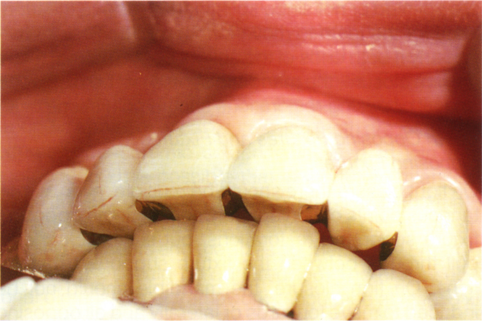
Fig. 33-8d Large horizontal : vertical ratio between CRCP and IP resulted in a distal movement of the mandible and this created a large horizontal overjet. This results in a shallow anterior guidance. Combined with fixture placement towards the anterior aspect of the ridge, the overjet produces wide teeth with an associated speech difficulty.
Guidelines for Posterior Disclusion
Factors which influence the space available to provide posterior disclusion are described on page 291.
Choice of Materials for the Occlusal Surfaces
Acrylic is advocated as the occlusal material for complete arch restoration, as this acts as a ‘shock absorber’.72 This has been verified with finite element analysis by Davis et al. (1988).73 However, these workers also reported that the increased rigidity afforded by porcelain coverage of the framework distributed the stresses generated by sustained forces, such as, those that occurred during bruxism, favourably with regards the underlying fixtures and abutment screws. Since sustained forces are more likely to occur than sudden ones, the choice of material is by no means certain and the clinician requires the results of controlled clinical studies to assist in decision making. Hobkirk et al. (1992)55 could not detect a difference in masticatory loads between porcelain or acrylic resin teeth, although it should be noted that the porcelain was retained on an acrylic base, which may have provided resilience. The Brånemark protocol emphasizes the importance of passivity of fit of the superstructure72 and fractures and fixture failures associated with porcelain occlusal coverage may not be related to the porcelain per se, but to lack of passivity of fit due to the framework distortion which occurs with ceramo-metal frameworks, unless these are post-ceramic soldered (Fig 9-13b), see page 203.
Acrylic resin has severe wear limitations if, for example, anterior guidance is provided on it, particularly if there is an acceptable porcelain reconstruction in the opposing arch. When acrylic teeth are used the anterior guidance should, if possible, be distributed between the canine, lateral and central incisors to reduce the likelihood of the acrylic fracturing from the underlying metal support. Zarb et al. (1993)74 reported high fixture survival rates after loading fixtures in partially edentulous spans for periods of two and a half years to seven years and four months when acrylic resin occlusal surfaces were provided.
Composite resin supported by a metal framework may provide a suitable compromise between acrylic resin and porcelain. However, it is possible that the loading on the material resulting from the non-mobile fixture supported bridge will be greater than that on a tooth supported bridge of similar span and this may lead to the fracture of composite resin. Quirynen et al. (1992)26 in a six year retrospective study of implant supported bridges in 168 partially edentulous jaws, reported no significant differences in the failure of fixtures supporting bridges with composite resin or porcelain, occlusal surfaces. The overall failure rate of 509 fixtures was six percent in periods of up to six years, but most of these failures occurred within the first year. Of loaded fixtures, the failure rate was less than two and a half percent. It should be noted that />
Stay updated, free dental videos. Join our Telegram channel

VIDEdental - Online dental courses


