Chapter 9
TOOTH PREPARATION, GINGIVAL RETRACTION, HYDROCOLLOID IMPRESSION TECHNIQUE, MASTER CAST SYSTEMS, SOLDERING
Principles of Tooth Preparation for Cemented Restorations
The following will be considered:
- Retention.
- Resistance.
- Margins.
- Parallelism.
- Occlusal reduction.
- Functional cusp bevel.
Retention
Retention form denotes those features of the preparation that counteract occlusally directed displacing forces. By conventional techniques, opposite ‘parallel’ walls provide retention. The longer and more nearly parallel the walls, the greater the retention. As a general rule, 10° of convergence, that is 5° taper should be aimed for, but see below. Although newer cements are being produced with claims of adhesive properties, the basic rules of tooth preparation should not be neglected. Auxiliary devices such as horizontal pins may be of value, but it is all too easy to be lulled into a false sense of security and neglect basic principles.
Resistance Form (Fig 9-1)
Resistance form comprises those features of the preparation that counteract displacing forces in all directions, other than occlusally. Such displacing forces are usually rotational and it is important to consider the possible rotations and which surfaces of the teeth, and hence which areas of cement, will resist these rotations (Fig 9-1a). The preparation should be designed so as to subject the cement to compressive stress rather than sheer stress. The dentist should examine the preparations for adequate resistance form. Note, that in figure 9-1a movement is potential movement and results in stress concentration within the cement. Shear stress is less well resisted (points 1 and 3) than compressive stress (2).
The Following Factors Influence the Resistance Form
- Magnitude of the applied load – bruxism on a non-working side contact will apply heavy loads.
- Direction of the load on non working side contacts – bruxism on a molar will result in buccally directed forces on the lower tooth and palatally directed forces on the upper tooth.
- Height of the preparation – the longer the preparation walls, the greater the surface area likely to resist rotational forces (Figs 9-1b–c).
- Width of the preparation – other factors being equal, the narrower the base, the greater the curve of potential rotatory movement, that is, the smaller the radius of the circle, and the greater the resistance form (Figs 9-1d–e).
- Location of the point of rotation – the more cervically this is, the better, since the rotation results in the crown engaging underlying tooth, which resists the rotation (Fig 9-1f).
- Rigidity and integrity of the tooth – a rigid core of for example, gold, will better resist rotation than a thin elastic stump – associated, for example, with a large access cavity in a root filled tooth which may contain microcracks.
- Taper of the tooth stump – the degree of taper influences the ability of the stump to resist potential rotation of the restoration (Figs 9-1g–h). It can be seen that curved or tapered surfaces may not engage potential rotations and would, therefore, not offer resistance.1 As the height of the preparation increases relative to the width, so the taper can increase and still offer resistance.
It can be seen, therefore, that the taper required is related to the height to width ratio of the prepared stump, and the concept that all preparations should have a 5° taper (that is, a 10° convergence) for adequate resistance form requires further consideration. Each tooth should be individually assessed prior to, and at the time of, preparation.
Fig. 9-1 Factors influencing resistance.
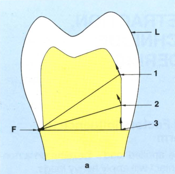
Fig. 9-1a Resistance form must counteract rotational forces. Rotation will occur about an axis through (F) contacting a rigid surface which is furthest from the load (L). Potential rotation occurs around (F). The inner surface of the crown engages the tooth preparation via the cement. Potential movement of any point, for example 1, 2, 3, is along an arc whose radius is from (F). At points 1 and 3 it is virtually parallel to the preparation and offers little, if any, resistance, at point 2 it engages the preparation and offers resistance.
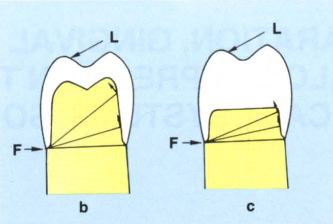
Fig. 9-1b Effect of height. A long preparation resists rotation.
Fig. 9-1c A short preparation is less capable of resisting rotation.
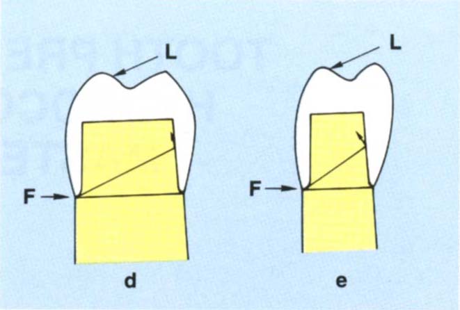
Fig. 9-1d A wide base. This creates a large radius of rotation meaning that the path of withdrawal is almost parallel to the axial wall of the preparation. The tooth does not offer good resistance form.
Fig. 9-1e Narrow base. Creates a shorter radius and more resistance form.
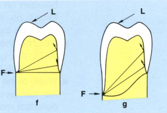
Fig. 9-1f/g Location of the margin – the further cervically the margin, the greater is the resistance.
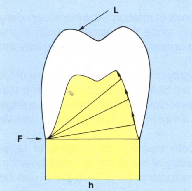
Fig. 9-1h Parallel sided preparation offers good resistance (Fig. 9-1f). A tapered preparation may not be able to resist rotations.
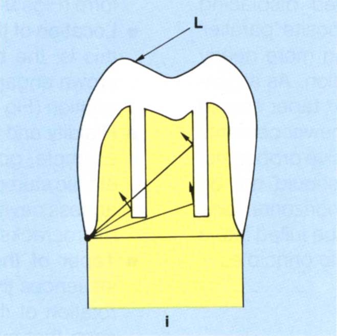
Fig. 9-1i Grooves – the further that a groove is placed from the axis of rotation, the more likely is the path of rotation to be towards the long axis of the groove. Note the occlusal portion of the groove engages better than the cervical portion.
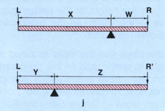
Fig. 9-1j Load L. The closer the resistance (R) is to the axis of rotation, the poorer are the lever mechanics.
for example, R needs to be larger than R’ to resist the same load L.
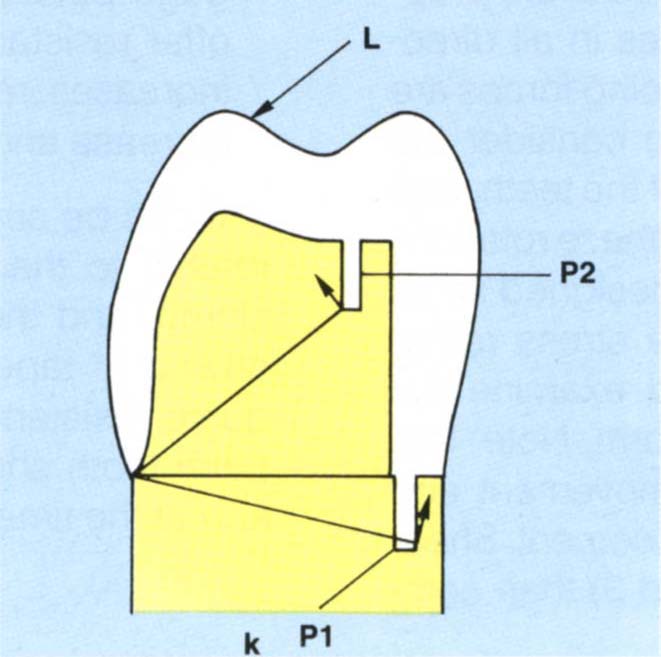
Fig. 9-1k Vertical pin resisting rotation. This should not be placed near a cervical margin (P1) because stress concentration in thin dentine can lead to fracture of the tooth. Pin P2 is more favourably positioned for the load L illustrated.
Factors that can Improve Resistance Form
- Lengthen the preparation – this will move the point of rotation cervically and increase the length of the stump.
- Reduce the taper – this will increase the surface area of the preparation which is available, to resist rotations.
- Place axial grooves – which will help to resist rotations (Fig 9-1i). The further the groove from the point of rotation, the more likely the path of rotation will be towards the long axis of the groove. The closer the groove is to the point of rotation, the more resistance will be offered. As can be seen from Figure 9-1i, it is the occlusal portion of the groove which is best positioned to resist rotations. Approximal groove near the buccal surface is close to the buccal point of rotation and will resist a buccally directed force, but is less able to resist a lingual rotation. However, the closer the resistance surface is to the point of rotation, the poorer the lever mechanics (Fig 9-1j). Overall, provided the groove will resist the anticipated rotation, remote placement is beneficial due to enhanced lever mechanics. The potential rotations must be anticipated and the preparation modified accordingly:
- Individual posterior units tend to rotate buccolingually.
- Individual upper anterior units tend to rotate buccally.
- Individual lower anterior units tend to rotate lingually.
- Bridges tend to rotate both as above and mesiodistally.
- Pins – vertical pins may assist in resisting rotation (Fig 9-1 k), but they should not be placed near the cervical margin of the preparation, as they are likely to generate high stresses in the tooth which may lead to cracking or fracture.2 Horizontal pins can increase resistance form, see page 423 Whaledent RX 90 kit.
Margins
Rosner, in 1963,3 described the angle of bevel as that angle formed by the created bevel surface with the surface which has been bevelled – that is, where there is no bevel the angle is 0 (Fig 9-2a). The shoulder angle is the angle formed between the axial wall and the line of the shoulder (Fig 9-2a).
A shoulder angle of between 90° and 135° (or heavy chamfer) with a bevel of approximately 60° and 15° respectively (Fig 9-2b) are useful and practical preparations. Convenient burs for placing the bevel are Premier Two Striper 292 and 285 (Figs 9-2c–d) each of which has three grits – 45, 25 and 10 microns. Reller et al. (1989)4 reported that final finishing of bevels was best carried out with 25 micron diamond coated finishing burs. The 10 micron bur should not be used since it produces smearing.
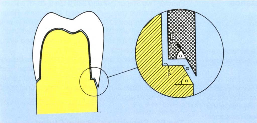
Fig. 9-2a The bevel angle is that angle formed by the created bevel surface with the surface which has been bevelled, that is, no bevel = bevel angle of zero. The shoulder angle is the angle formed between the axial wall and the line of the shoulder. This preparation has a 90° shoulder angle and a 60° bevel angle.
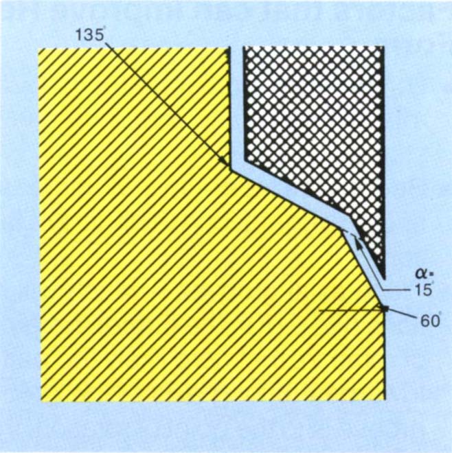
Fig. 9-2b 135° shoulder with bevel of 15°. This bevel represents 60° to a 90° shoulder angle.
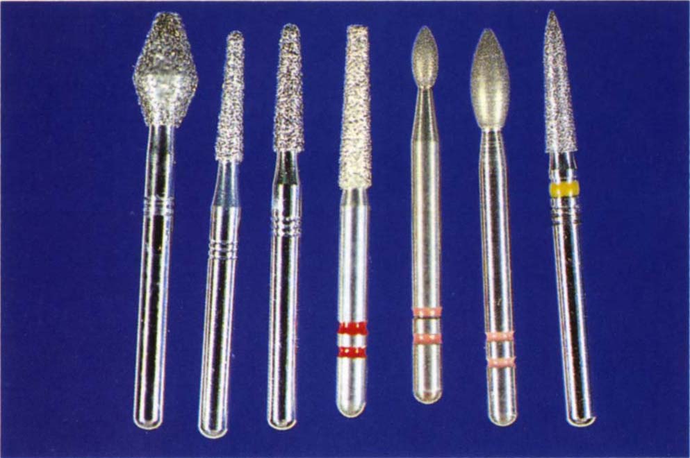
Fig. 9-2c Densko diamonds: 461 – reduces the occlusal surface; half DT and 1 DT for axial reduction. These are available in coarse, normal and fine grips. Premier 703.8f for preparing shoulders. Premier Two Striper 292 and 285 composite finishing diamonds. These are useful for placing bevels. The 45 micron (red band) and 25 micron (coral band) grits are used. Densco 1 ASF: for placing bevels in areas of limited access.
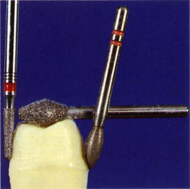
Fig. 9-2d Tooth preparation showing the use of a Densco 1 DTF to smooth the axial reduction and chamfer (preceeded by a 1 DTX), a Densco 461 for occlusal reduction, a Premier 292 for creating the bevel beyond the chamfer. The handpiece must be angulated to the tooth as shown, so as to prevent the 292 bur producing axial undercuts.
When aesthetics are of prime concern a buccal shoulder and lingual bevel will be the margin and finishing lines of choice,5 assuming that the tooth anatomy is favourable and there has been no pronounced gingival recession buccally.
The 90° Shoulder or Heavy Chamfer with a Bevel of 60° or 135° Shoulder with a Bevel of 15°
It has the Following Advantages
- It provides a good bulk of metal.
- It is easier to produce a smooth preparation and distinct finishing line with a bevel than with other finishes. In my experience, this is the most critical factor. A smooth bevel is clearly visible when trimming dies and can be accurately worked to by the technician. With careful technique excellent crown fit can be obtained. Regardless of their theoretical merits, if other types of finish do not routinely produce a smooth and visible margin, the clinical result will not match the theoretical expectations.
- There is good closure of the marginal gap between restoration and preparation (Fig 9-2e).6, 7
- It is very suitable for hydrocolloid technique. Dies made from reversible hydrocolloid impression material are on average 20 microns narrower than the original preparations.8 If 35 microns of die spacer (7 coats) are used on the axial surfaces of the die, there will be 25 microns of space for the cement. At the margins however, the casting will be on average 10 microns too narrow on each side. The margin will, therefore, bind before complete seating of the crown (Fig 9-2e). A long shallow bevel will ensure that, although not completely seated, the marginal gap will be greatly diminished, the actual width being determined by the film thickness of the cement. The errors incurred by incomplete seating are clinically insignificant.
- Shillingburg et al., in 19739 reported minimal metalwork distortion due to porcelain firing, although McLean and Wilson (1980)10 recommended either a flat shoulder or a chamfer with a 1 mm gold collar.
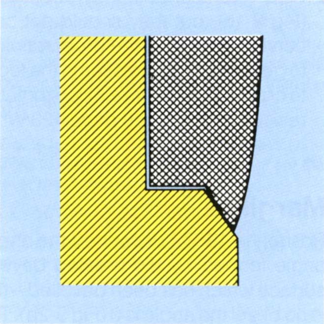
Fig. 9-2e Good closure at the margin. If the casting is tight at the margin but there is a die spacer on the axial walls, then the casting will still close on the bevel. The crown margin is inside the finishing line.
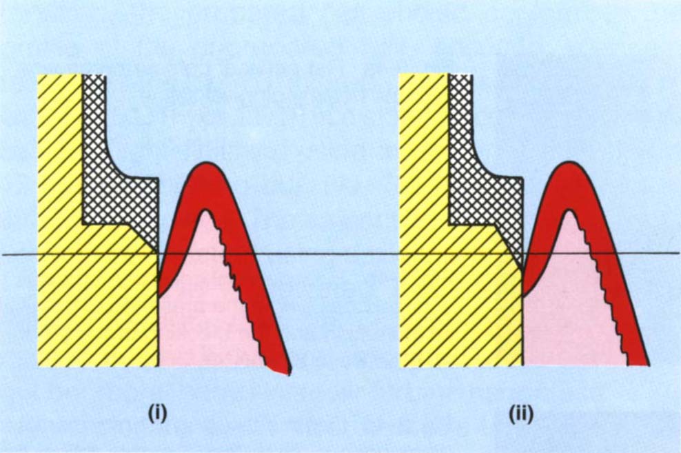
Fig. 9-2f A 45° bevel (i) extends less into the sulcus than a 60° bevel (ii) (after McLean and Wilson, 1980). The greater the bevel angle, the further the extension into the sulcus.
It has the Following Disadvantages
- It is difficult to wax and cast to, as the edge of the bevel is very thin.
- It can extend too far towards the epithelial attachment.10
- If this region of the restoration is covered with porcelain it may distort. This can be minimised by ensuring that the gold collar is at least 1 mm high.
- A 1 mm gold collar may produce an unaesthetic ceramo-metal restoration.
Occlusal Reduction
There must be sufficient tooth removal to allow an adequate bulk of restorative material occlusally, 1 mm for gold, 1.5 mm for ceramo-metal restorations.
Functional Cusp Bevel (Fig 9-3)
When there is a normal buccolingual relationship between the opposing teeth, preparations must include a functional cusp bevel: palatal inclines of upper preparations and buccal inclines of lower preparations must allow sufficient room for the restorative material. Failure to incorporate a functional cusp bevel frequently results in a ‘high’ restoration, the technician being forced to thicken the wax to ensure satisfactory casting. Subsequent reduction of the ‘high’ area results in perforation.
Crown Preparation Technique
The preparation should be so designed as to allow for an optimum thickness of restorative material. Furthermore, the restoration should have good anatomic form, particularly in the cervical third. When margins are placed subgingivally, it is imperative that the angle of the crown to the marginal gingiva is correct (Fig 9-4) and that the crown is not bulbous11 (Figs 9-4a–b). As a general rule, 1 mm of reduction is required for gold restorations, 1.25 mm for porcelain and 1.5 mm for ceramo-metal and heat cured composite restorations. There is a large discrepancy between ‘a dental millimeter’ (that is, what the dentist assesses as a millimeter) and a real millimeter. It is advisable initially to place depth cuts in the tooth, a 557 bur, being 1 mm in diameter, is useful for this purpose. The bur is sunk into the tooth to the requisite depth; as the preparation should follow the natural angulations of the tooth surface, three planes of cut on the buccal and lingual surfaces are usually made (Fig 9-4c).
Fig. 9-3 Functional cusp bevel. Buccolingual diagram (BU = buccal, L = lingual) through the first molars to illustrate.
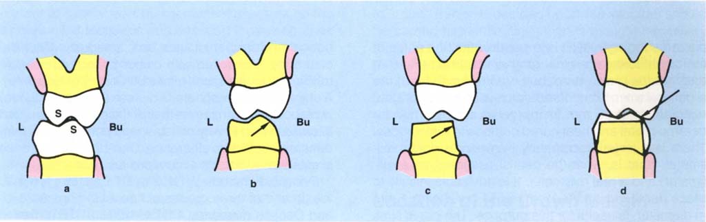
Fig. 9-3a Support cusps S – buccal lower, palatal upper.
Fig. 9-3b Preparation which has a functional cusp bevel, arrowed.
Fig. 9-3c Lack of functional cusp bevel, arrowed.
Fig. 9-3d Results in a high crown since the technician requires a minimal thickness for wax. Perforation will occur during adjustment, arrowed.
Fig. 9-4 Cervical contour of crown.
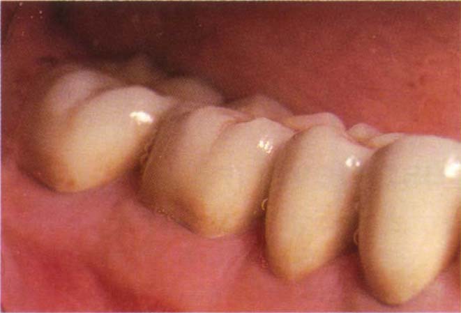
Fig. 9-4a Flat cervical contour on crowns – note the healthy gingival tissue.
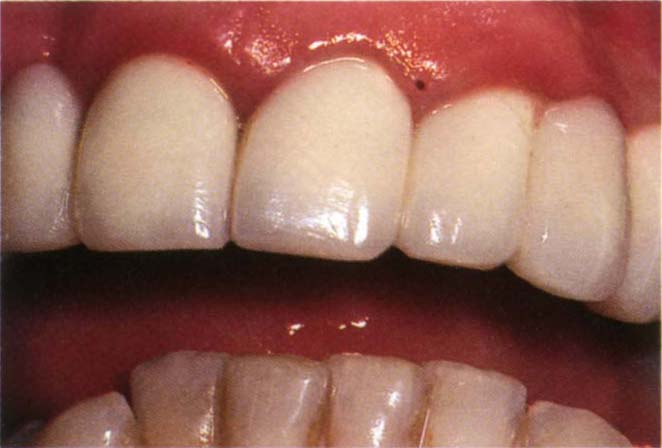
Fig. 9-4b Poor cervical contour on crowns – over bulbous – note the presence of gingival inflammation and the blocking of the embrasure between 22 and 23.
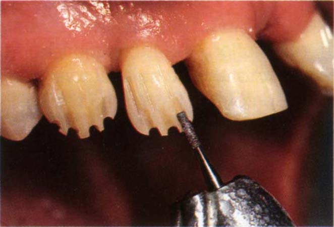
Fig. 9-4c Depth cuts using a 1 mm diameter diamond bur. Note that the cuts follow the contours of the tooth. Preparation of the mesial half will then leave the distal half intact and its profile acts as a guide to even reduction.
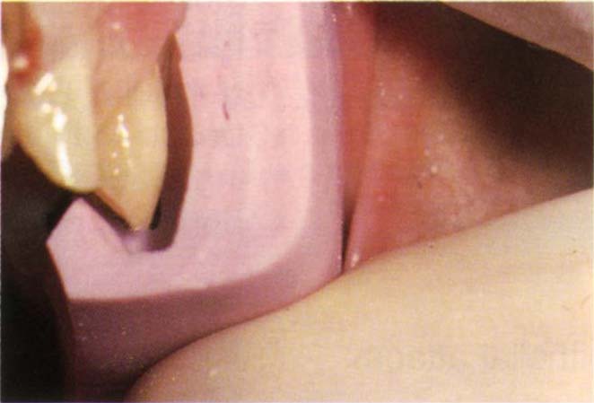
Fig. 9-4d A silicone index, made before preparation, has been cut vertically. The profile of the uncut tooth acts as a guide to tooth reduction. Note the even reduction following the original tooth contour.
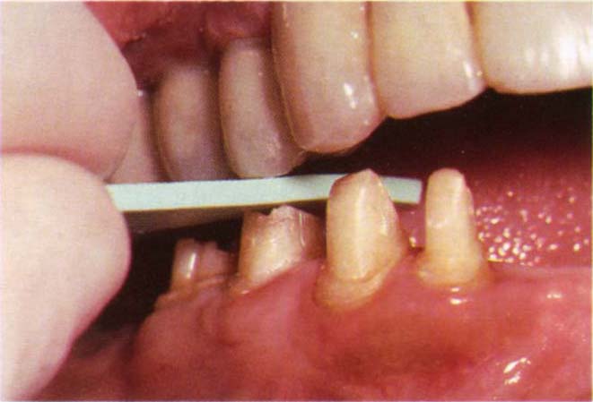
Fig. 9-4e Belle de St Claire 1.5 mm shim held between opposing tooth and preparation. The shim pulls out indicating at least 1.5 mm clearance.
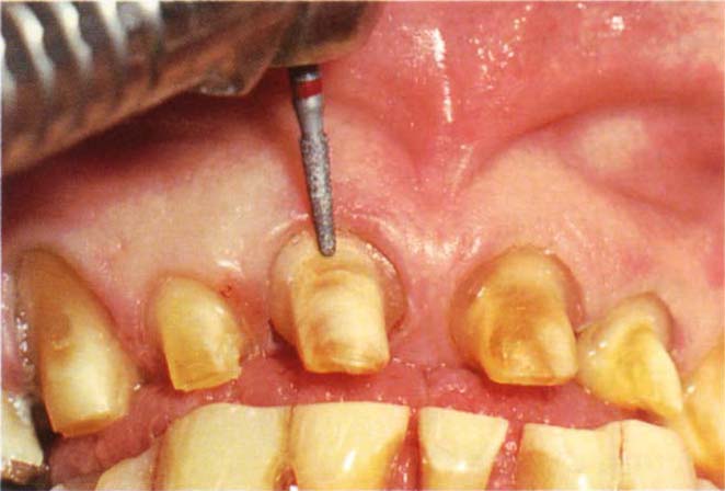
Fig. 9-4f Finishing the shoulder with the bur approaching from the buccal aspect.
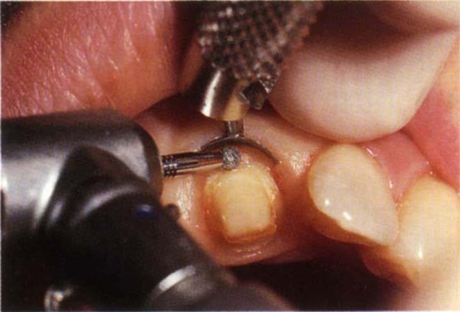
Fig. 9-4g Zekyra Gingival Protector in place prior to finishing the margin.
Occlusal reduction is readily accomplished with a Densco diamond No 461 (Figs 9-2c–d). This will reduce buccal and lingual inclines simultaneously. Occlusal clearance is checked with colour coded, disposable rubber thickness shims (Belle St. Clare Co) (Fig 9-4e). A shim of the appropriate thickness (1 mm or 1.5 mm) is placed between the teeth and the patient instructed to close in the I P. Any resistance to pulling of the shim denotes insufficient clearance. Once the I P clearance is established, lateral excursions are rechecked.
Densco diamonds ½ DTX, ½ DT, ½ DTF (½ mm at the tip and of three grades of fineness) (Figs 9-2c–d) and Densco diamonds 1 DTX, 1 DT, 1 DTF (1 mm at the tip) are very useful for axial reduction. Both are available in an extra long ‘L’ range (such as, 1 DTLF). Either the mesial or distal half of the tooth is first prepared using the depth cuts as guides. Preparation of one half of the tooth leaves the remaining half as a further guide. Unless repositioning of the crown is required, the prepared half should conform to the profile of the unprepared half, ensuring adequate removal of the tooth. The preparation is smoothed with either a ½ DTF, or 1 DTF in a slow handpiece, followed by very ‘light’ finishing using a Jet, Tungsten Carbide 12 bladed finishing bur, No. 7664 (Jet Ltd) in an air turbine handpiece. The amount and contour of reduction can be checked using a silicone index (Fig 9-4d).
When a bevel is indicated, it is prepared using a Premier Two Striper No. 292 or 285 (Figs 9-2c–d) of 40 micron grit (red band) and smoothed with a 25 micron grit bur (coral band) in an air turbine handpiece.
Occasionally the Premier burs are too wide to use approximally, without damaging an adjacent tooth. In such cases a narrower Densco 1 ASF bur (Fig 9-2c) is useful. It should be appreciated, however, that the larger the diameter of the bur, the smoother will be the finish. If the finishing line is to extend into the gingival sulcus, then 00 Ultrapack (Ultradent Co.) retraction cord is placed in the sulcus prior to preparing the bevel (see below for technique).
When a shoulder is indicated, it is prepared with either a 1 DT bur or a flat ended Premier 703.8C and finished with the finer Densco 1 DTF or Premier 703.8F, or a round diamond bur (Fig 9-2c). If the 703.8C bur is used, great care must be taken to prevent a stepping effect at the shoulder. The latter should be prepared coronal to the desired level and then refined with a one mm diameter round bur. The shoulder is then planed with chisels. Provided there is adequate access, a smoother shoulder is prepared as follows. A piece of 00 Ultrapack retraction cord is placed in the gingival sulcus and a Densco 1 DTF bur in an airturbine handpiece, then used with the bur perpendicular to the buccal aspect of the preparation (Fig 9-4f). Running the bur at slow speed by intermittent pressure on the air controlled footpiece and ensuring the bur tip does not gouge the axial surface of the preparation, the shoulder is gently planed.
Although 12 and 40 bladed tungsten carbide burs can produce very smooth margin finishes,4 my experience is that these finishes can be ridged and that, generally, a smoother, less ridged margin is obtained with fine diamond burs, preferably of large diameter. A very useful gingival retractor and protector (Zekyra Gingival Protector – Maillefer) is illustrated (Fig 9-4g). This does not allow a buccal approach for shoulder finishing, but does protect the gingiva.
Following the completion of the preparation, the tooth is gently cleaned of debris with a mixture of flower of pumice and water, using a rubber cup in a slow speed handpiece (green band).
For further details, the reader is referred to Pameijer (1985), Chapter 8.12
Porcelain Butt Fits (Fig 9-5)
If the presence of a gold collar will produce an unaesthetic ceramo-metal restoration, provided that a shoulder angle of between 90° and 135° can be prepared (preferably 90°), then a porcelain butt fit restoration should be provided.
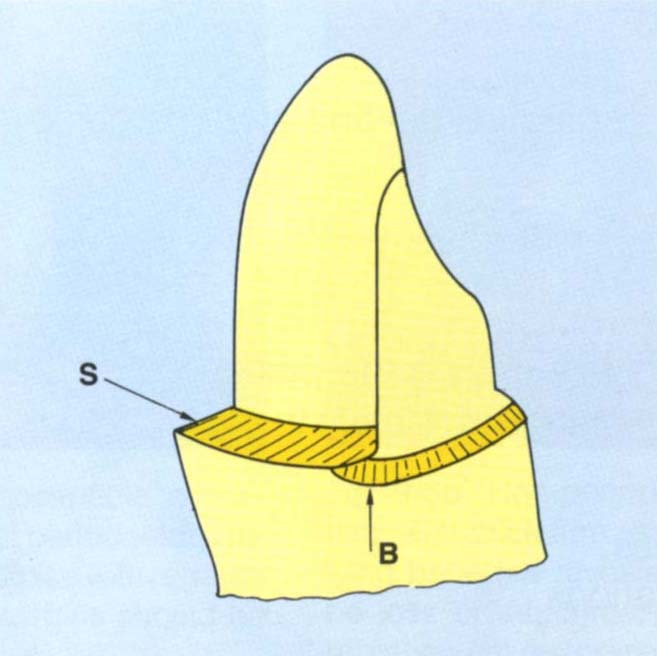
Fig. 9-5 Porcelain butt fit preparation. The shoulder (S) should be prepared to pass further lingually than intended for the porcelain fit. A bevel (B) is then placed, which removes some of this shoulder. The buccal portion of the preparation has greater axial reduction than the lingual portion.
It is necessary to prepare a shoulder on the buccal surface and a bevelled finishing line toward the lingual surface of the preparation. The transition from one finishing line labially to a different one lingually is difficult to prepare and difficult for the technician to wax to. If such a finish is decided upon, the shoulder should be carried further lingually than is thought necessary (Fig 9-5) and then a bevel placed to pass buccal to the mesial and distal extension of the shoulder. This removes part of the shoulder but provides a smooth transition from bevel to shoulder. The metalwork is carried onto this bevel and swept upwards and forwards.5, 13–14
For laboratory details, see Appendix.
Location of the Crown Margin
The periodontal literature would imply that all crown margins should ideally be placed supragingivally,15 the following factors need to be considered in deciding marginal location.
- Aesthetics.
- Periodontal health and tissue response.
- Caries.
- Finishing.
- Protection of supragingival dentine and enamel.
- Fractures.
- Medical history.
Aesthetics
The primary factors influencing the positioning of the labial/buccal crown margin in relation to aesthetics are:
- Lip line.
- Gingival thickness.
- Patient’s expectations.
Lip Line
The visibility of crown margins is dependant upon the functional lip line. This should be carefully assessed on a number of occasions, the assessment must be made before the administration of any local anaesthetic. A low upper lip line enables maxillary margins to be positioned supragingivally and the restoration to have a metal edge, whereas a high lip line may necessitate subgingival location with a metal or porcelain margin. Sometimes it is possible to use a porcelain margin, finishing at the gingival crest. It must be remembered that high lip lines can expose all buccal margins or just the margins anteriorly or just the posterior margins. It is helpful to take Polaroid photographs of the smile line. The print is sent to the laboratory to help in determining the width of metal collars on ceramo-metal crowns. A low lower lip line produces similar problems to a high upper lip line.
Gingival Thickness
Thin gingival tissue is often positioned over a dehiscence or fenestration in the underlying bone. Inflammation of the crestal tissue – which will often result from instrumentation during crown preparation, cementation and from the presence of the crown margin – can lead to a union of the oral and sulcular retepegs, causing breakdown of the epithelium with cleft formation and exposure of the crown margin. In such cases, the aesthetic result suffers and it is better to be realistic and prepare the margin at the gingival crest. Tissue thickness can be assessed by gently placing a periodontal probe into the sulcus and observing tissue displacement and how visible the probe is through the gingiva. Thick tissue will show minimal or no displacement and the probe will be barely visible.
The crestal height of the bone can sometimes be seen on long cone periapical radiographs. Even if not visible, the crestal location can be projected from the borders of the approximal crestal images. Occasionally ‘sounding’ is used. Under local anaesthetic, a straight probe is pressed through the gingivae to assess the location of the underlying hard tissue as bone or tooth.
Patient’s Expectations
Often if the hazards of subgingival margin location to gingival health are explained to patients, they will opt for aesthetic compromise.16 However, it should be noted that the same workers reported that the commonest reason for patient dissatisfaction was visible crown margins. Certainly, when the primary cause of failure is aesthetic, great caution must be exercised when prescribing further aesthetic compromise. ‘Think twice’ before using a supragingival margin.
Periodontal Health and Tissue Response
There is little doubt that gingival and periodontal health are compromised by subgingival margin location17–18 and in particular by subgingival overhangs.19–20 However, this does not mean that all margins must be located supragingivally. Freilich et al. in 199211 reported that well fitting fixed bridge retainer margins located up to 1 mm subgingivally had no effect on periodontal probing depths or bleeding on probing, when compared with non-restored teeth. However, retainer margins located 2 mm to 3 mm apical to the gingival crest exhibited significant periodontal changes. From the periodontal viewpoint, the primary factor to be considered is the susceptibility to periodontitis.
No compromise should be made with patients who have lost periodontal support and are obviously susceptible to the disease (Fig 9-6a), and wherever possible margins should be supragingival. On the other hand, the patient with thick firm tissue, dense underlying bone and no loss of attachment (Fig 9-6b) is probably immune to periodontal disease, and although subgingival location may cause some marginal inflammation, there is not reason to suppose that this will convert the patient into a periodontitis susceptible individual. Obviously there are patients between these two extremes. Lang et al., in 1983,21 reported that the subgingival placement of extremely well-fitting gold restorations did not alter the bacterial flora, whereas similar restorations with overhangs altered the flora towards gram negative melanogelic organisms, which are associated with periodontitis. In this well controlled study bleeding tendency gradually increased with well-fitting subgingival restorations, but there was no loss of attachment. From the periodontal viewpoint, therefore, if for some reason subgingival margins are indicated, a marginal adaptation must be as accurate as possible. It has been reported that clinically acceptable retainers with clinically detectable deviations of slight overextension or underextension of margins had significantly greater gingival index scores than matched non-restored teeth.11 Newcomb in 1974 reported that the closer the crown margin was to the base of the crevice, the greater the amount of gingival inflammation.22 Inflamed gingivae will, of course, give rise to poor aesthetics (Fig 9-7).
Fig. 9-6 Periodontal health and margin placement.
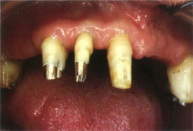
Fig. 9-6a Patient who is susceptible to periodontal disease and has lost periodontal support cannot tolerate compromise with regards to the periodontium. The margins should be supragingival.
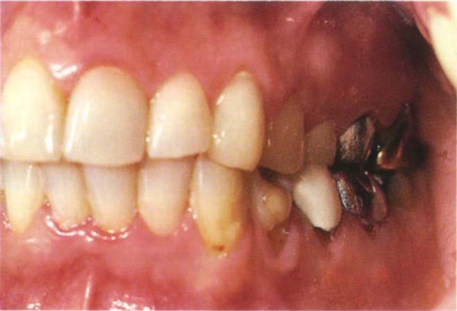
Fig. 9-6b Non periodontitis-susceptible patient with thick firm tissue and dense underlying bone (as revealed on radiograph) and no loss of attachment. The margins of the replacement restorations can be placed subgingivally without fear.
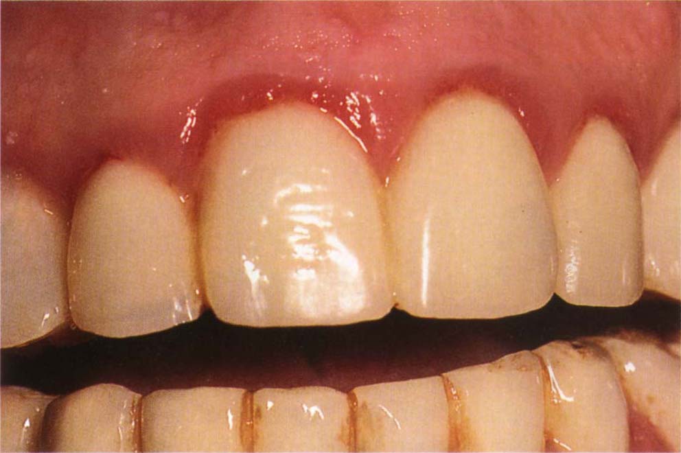
Fig. 9-7 Inflamed tissue gives rise to poor aesthetics.
Caries
There is little doubt that caries is a primary cause of failure of restorations.23–25 Black, in 1947, advocated subgingival marginal location, since ‘this would be in a caries immune zone’.26 Black’s conclusion was drawn from the observation that the enamel gingival to the contact areas of the extracted premolars of 14 year olds showed no decalcification. Being unaware of the presence of junctional epithelium, which in the 14 year old would still be adherent to the enamel, he did not realise that the enamel he was observing had never been exposed to the oral environment, being protected by the adherent epithelium. It was reported by Valderhaug et al., in 1976 that subgingival margins do not have a lesser frequency of caries than supragingival ones,18 in which case there is no indication for subgingival location from a caries protective standpoint. This issue is not entirely resolved, however.
Ramfjord (1988), for example, stated that there is no caries protective benefit from subgingival margin placement, yet he also states that one of the consequences of pocket elimination is an increased susceptibility to root caries.15 If this is so the implication is that the pocket imparts resistance to caries of the root surface. Infrapocket positioning of the margin would, therefore, be in a less caries susceptible area. This observation obviously requires further investigation and is not being advocated for clinical practice.
Finishing
There is a direct correlation between the fit of the crown margin and recurrent caries.24 It is easier to finish, make an impression, check and clean supragingival margins than subgingival margins. However, this does not mean that it is impossible to achieve the required quality with subgingival margins. The result will be determined by:
- The access.
- The tissue thickness (my clinical experience is that thick tissue is less readily irreversibly damaged and less likely to bleed than thin tissue).
- The clinician’s ability. This may be the most important factor and should not be underated. It is essential that the dentist is realistic about his own ability.
Protection of Supragingival Dentine and Enamel
It is very difficult to finish margins on cementum and dentine. These tissues are relatively soft and will be damaged by finishing procedures. By the same token, however, exposed supragingival dentine may be damaged by toothbrushing (Fig 9-8a), or maintenance instrumentation. An enamel margin is easier to finish, but enamel left exposed beyond the margin can be damaged by erosion. In some instances, therefore, it is best to cover all supragingival structure. With severe recession because of taper of the root, it may not be possible to extend the preparation subgingivally, or to the gingival crest, without unwarranted destruction of the remaining tooth and danger to the pulp (Fig 9-8b).
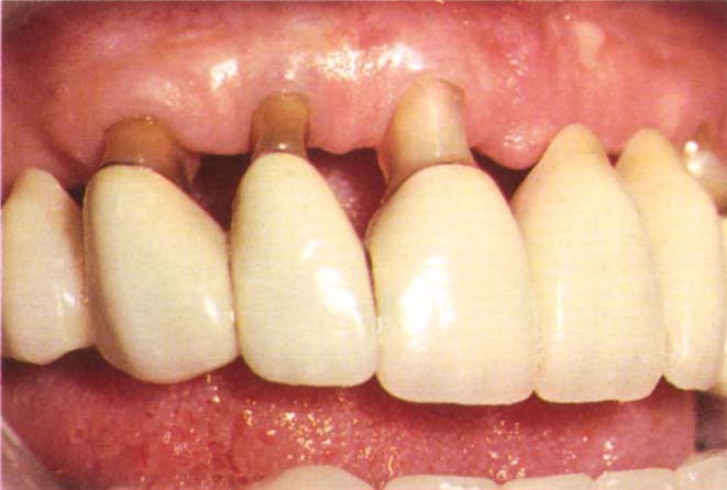
Fig. 9-8a Supragingival dentine damaged by tooth brushing. Note the narrowed roots which are now susceptible to fracture.
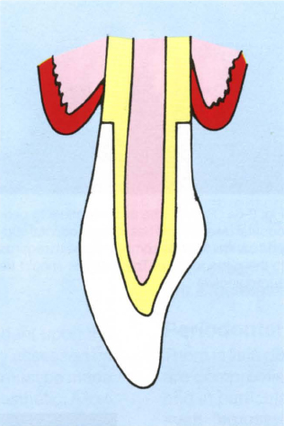
Fig. 9-8b With advanced recession the tapered root is exposed. Shoulder preparation at the gingival margin may be excessively destructive of tooth structure and this may jeopardize the pulp. Remember that the pulp chamber is usually wider bucco-lingually than mesio-distally. Radiographic interpretation can be misleading.
Fractures
Subgingival tooth fracture may necessitate clinical extension of the crown margins subgingivally. Clinical crown lengthening (Chapter 20) and rapid orthodontic extrusion (Chapter 24) are sometimes indicated. On other occasions it is better to extract the tooth and place an osseointegrated fixture, fixed bridge, or removable partial denture.
Medical History
A history of any condition rendering the patient susceptible to infective endocarditis is an indication to keep subgingival instrumentation to a minimum, as are any factors which predispose towards marginal inflammation.
Parallelism – the Correction of Small Discrepancies
For fixed bridgework, unless interlocking screws are to be used, it is necessary to provide parallel or near parallel (10-15° of convergence) preparations. Since interlocks complicate laboratory procedures and cementation – any small discrepancies between screw and threaded channel will lead to non-passive seating of the units or open margins due to non-seating of the units, it is preferable to use near parallel preparations. Sometimes at the provisional restoration stage it is found that preparations are slightly out of parallel. Corrections can be made in the laboratory, see Appendix and DuraLay copings made to guide subsequent tooth modification. Just before seating the provisional bridgework, the DuraLay coping is placed on the preparation which is then modified by carefully reshaping the preparation protruding through the window in the coping (Fig 9-8c). This allows the provisional restoration to be seated and also finalises the preparation.
Fig. 9-8c Correction of small discrepancies in parallelism. The distal surface of 44 is undercut relative to 43.
Stay updated, free dental videos. Join our Telegram channel
VIDEdental - Online dental courses


