The Celay System
The Celay (Ceramic Inlay) System was developed in 1988 at the Clinic for Fixed and Removable Prosthodontics at the University of Zürich, Switzerland in cooperation with Microna Technologie (Spreitenbach, Switzerland) (Eidenbenz 1992). The goal was to produce strong and highly aesthetic inlays as efficiently as possible. The basic idea was to produce an individual, well-fitting ceramic component from an industrially prefabricated ceramic block. The use of a more homogeneous ceramic material with optimized physical properties represents a substantial advantage compared to ceramics constructed in the dental technician’s laboratory. Today, the Celay system is mainly used to manufacture ceramic inlays and onlays in the laboratory. It is also combined with the In-Ceram technique (Celay In-Ceram) to manufacture aluminum oxide (Al2O3) as well as spinel (MgAl2O4) frameworks for single crowns and small anterior bridges.
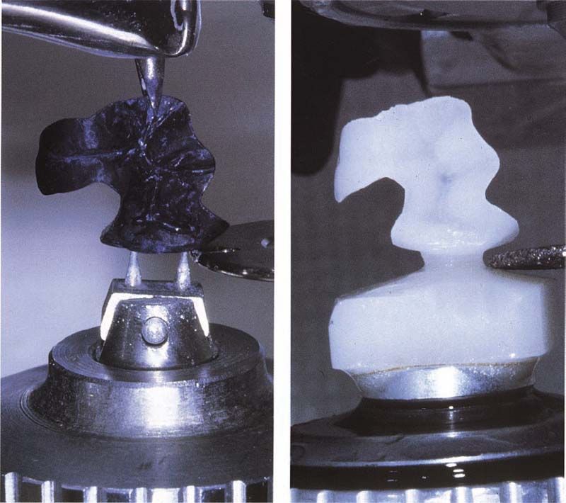
456 Copy-milling procedure
Left: Mechanical sensoring of the reconstructed inlay.
Right: Synchronous milling of the ceramic inlay from an attached ceramic block (Celay Blank).
Copy-Milling Procedure
In contrast to the Cerec system, the Celay system does not use an “optical impression” to create a model, from which information is taken and used by a computer and transferred to a mill. Instead, the model (pro-inlay or pro-crown) is preformed using a light-cured resin on the master model (Celay Tech).
The piece is fixed in a special attachment unit and a three-dimensional construction is copied by means of mechanical sensoring and synchronous milling. The degree of freedom and the interpretation of the Celay system’s reader allows it to shape any forms from industrially presintered ceramic blocks (Vita Celay Blank or Vita Celay Alumina Blank). The copy-milling unit is driven by an air turbine (4.2 bar, 80 m/sec).
Technical Procedure
Based on the size of the piece to be copied, the ideal ceramic block is first selected from a number of different sizes of prefabricated blocks and fixed in the milling unit. Ceramic blocks are available to the technician in the Vita Colors A4, A3, and A3.5.
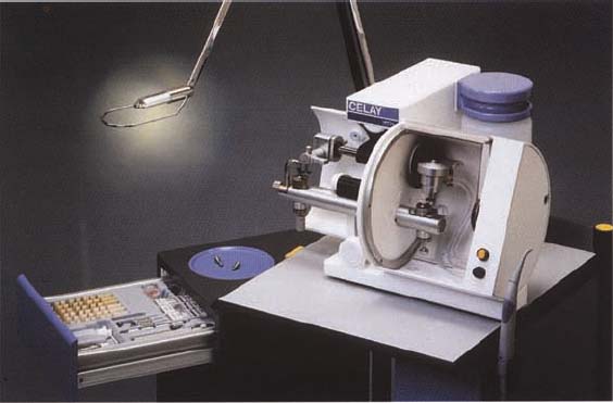
457 Celay machine
The sensoring device is on the left, the milling unit on the right.
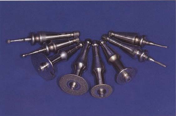
458 Scanning devices (disk, cylinder, ball) have exactly the same shape as the corresponding milling instruments
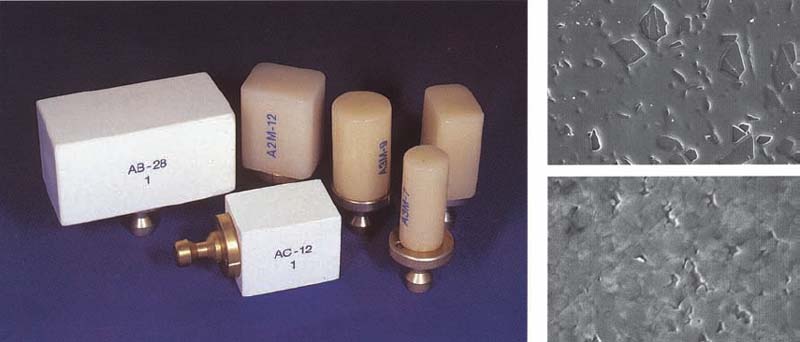
459 Ceramic blocks
Prefabricated ceramic blocks for inlays (Vita Celay Blank; A2/A3) or crowns as well as bridges (Vita Celay Alumina Blank; white).
Right above: Vita Celay inlay ceramic (feldspar ceramic; flexure strength 123 ± 15 MPa; magnification x 1000).
Right below: Vita Celay alumina ceramic (infiltration ceramic; flexural strength 547 ± 13 MPa; magnification x 3000).
SEM micrographs: H. Lüthy
The mechanical scanning of the pro-inlay or pro-crown attached to the scanning unit is carried out with different scanning tools. These tools correspond in form to diamond-coated milling tools. The shape of the piece is copied and roughly cut with the cutting tool (124 μm) under continuous water cooling with three nozzles aimed at the ceramic platform.
In a second step, the different milling diamonds are replaced by correspondingly finer finishing disks and cylinders (64 μm) and the final shape of the ceramic piece is milled with the help of touch control.
A very thin layer of white powder is sprayed onto the prefabricated plastic body as touch control and serves to provide an overview of the scanning process. It is not until after finishing is completed that the fit of the inlay or the crown cap can be optimized by carefully trying it on the master model.
Preparation and Fit
Inlays and Onlays
A mechanically shaped inlay or onlay (e.g., Celay or Cerec) is dependent on the availability of a careful, smooth preparation with perpendicular outer preparation margins, since irregular sections can only be reproduced to a limited degree due to the size of the milling tool. The cavity surface should have no sharp-edged transitions, because these concentrate stress (possible fracture locations) that will lead to fracture of the tooth and/or the inlay.
In vitro evaluations of composite and ceramic inlays show that composite inlays and pressed ceramic inlays have the best average fit (10–50 μm). The optimal fit of a shaped Celay inlay, measured over the entire marginal length, is between 50 and 80 μm and is comparable with the Cerec 2 generation. It is also comparable with perfect, laminated inlays. The fit of ceramic inlays can, from a technological point of view, be efficiently optimized with a mixture of wax and ceramic (Celay Optimizer).
The advantage of the Celay system as compared to the new Cerec 2 generation is that the occlusal and interproximal anatomy of inlays and the form of the framework of the crown can be individually shaped.
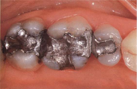
460 Initial situation
Old, defective amalgam restorations located in the first quadrant.
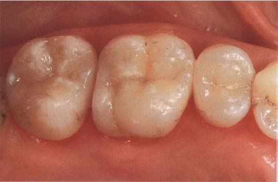
461 Clinical end result
Adhesively cemented ceramic Celay inlays (tooth 17, MOD; tooth 16, onlay; tooth 15, DO).
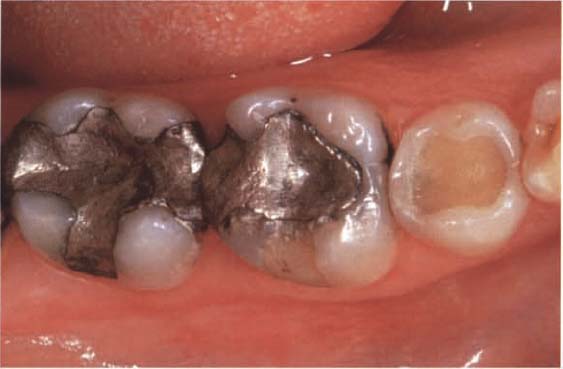
462 Initial situation
Old, defective amalgam restorations located in the fourth quadrant.

Stay updated, free dental videos. Join our Telegram channel
VIDEdental - Online dental courses


