CAD/CAM in Restorative Dentistry
The aim of developing computer-controlled production technologies for use in restorative dentistry is to improve the quality of the construction units and at the same time to lower manufacturing costs by simplifying the method and reducing the production time. More than ten different computer systems have already been described in the literature for dental applications and have also to some extent been used clinically (Rekow 1993). The use of computer technology is justifiable only if computer-assisted design (CAD) and computer-assisted manufacturing (CAM) produce dental reconstructions that fulfill or improve existing material characteristics and/or clinical quality (Besimo et al. 1995).
The computer-assisted systems known today differ mainly with regard to the type of three-dimensional data recording system used to image the prepared tooth. In contrast, the automatic manufacturing (CAM) of the pieces is quite similar and consists mainly of a numerically controlled (NC) machine with a material-specific milling unit that can be moved in three axes in relationship to the piece being worked on (Becker and Heidemann 1993). The precision of the optical recording unit is achieved with a charged coupled device (CCD) image recorder (e.g., Cerec) and is dependent on the number of pixels (Schlegel et al. 1991). This also determines the resolution of the combined CCD camera and three-dimensional scanning through laser triangulation (e.g., Sopha and Cicero).
The Cerec system has for some time now made intraoral data recording possible. Thanks to the short exposure time, it is no longer necessary to temporarily attach the camera to the jaw. However, the precision of the method is not only restricted by the resolution of the image recorder, but also by the coating that needs to cover the tooth surface to enhance the contrast between the projected lines and the tooth surface (Becker and Heidemann 1993).
Modern mechanical sensing methods (e.g., DentiCAD and Digitizing Computers System [DCS]) in principle allow higher resolutions (Schlegel et al. 1991) than optical systems. In addition, they are capable of reading details intra-orally, thus permitting the location of subgingival parts of the crown preparation. In general the miniaturization of purely mechanical digitizing units has not yet progressed to a point when they are useful directly in the oral cavity. Moreover, the sensing device must be attached to the jaw during the digitizing procedure. Another problem is the physiological mobility of the supporting teeth. This can cause reading errors that can be avoided during intraoral recording with the touch-free optical data recording systems. Therefore, today’s computer systems equipped with mechanical readers are only and exclusively used on the model (Becker and Heidemann 1993).
A possible parameter for judging the performance of a production method is the marginal fit of the pieces. Reactions in the literature to the marginal adaptation of complete casts or metal-ceramic crowns made with the traditional casting technique have been mixed. As different studies have shown, the average gap size of 20 μm can be achieved under optimal laboratory or clinical-experimental conditions (Belser et al. 1985; Böttger et al. 1988). These results are in conflict with clinical observations. In a retrospective cross-sectional study, Diedrich and Erpenstein (1985) found that of fifteen partial and full crowns produced under uniform practice and laboratory conditions, the average gap width was 91.5 ± 89.1 μm.
Possibilities and Limitations of Computer-Controlled Production Technologies
Using the Cerec system, the average gap size under experimental conditions of uncemented ceramic inlays is 100–150 μm (Hahn 1990; Peters and Dieniek 1991; Rose et al. 1990).
The DentiCAD System enables an average gap size of 23 ± 23 μm for single crowns. The measurements ranged from 1 to 49 μm (Rekow et al. 1991).
The DCS described below achieves an average marginal fit of 47.0 ± 31.5 μm in the newest in vitro studies on crown frameworks made from titanium. The data ranged between 0 and 220 μm. Of the measurements, 6.8% exceeded 100 μm, usually caused by titanium chipping in the marginal area of the crown margins (Besimo et al. 1995).
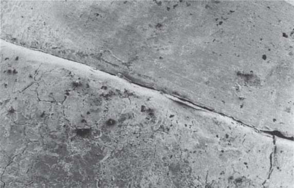
483 Margin area of a crown framework milled in titanium using the DCS System
C Crown
T Tooth
SEM micrograph, magnification x 50
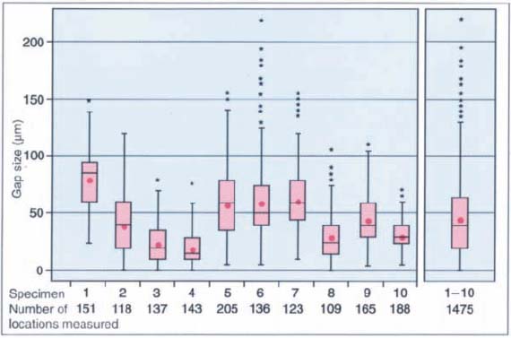
484 Variations in margin gap size of ten DCS frameworks milled in titanium
The boxes include the 25th to 75th percentile of the observations. The small stars mark extreme values; the red dots represent mean values. The line within the box indicates the median. The number of measurements for each crown examined by SEM is shown below the diagram.
(Adapted from Besimo et al. 1995.)
Stay updated, free dental videos. Join our Telegram channel
VIDEdental - Online dental courses


