In all cases of maxillofacial trauma, formal clinical appraisal, preferably by a specialist, should precede imaging. Some facial injuries require no imaging at all; others necessitate complex image investigation, so it is essential that the specialist’s examination focus on the most appropriate imaging. Many factors are involved in the process, and success is heavily dependent on good teamwork among the surgeons, nursing staff, radiographers, and radiologists.
In deciding whether a patient requires imaging, it is important to remember that that there will be a radiation dose to the patient as well as a time and financial cost. Although the radiation dose from a simple orthopantomogram (OPG) is low, there are many glandular structures in the head with a high cell turnover. These have a higher susceptibility to radiation effect. Patient presentation varies enormously, from an alert patient who has received a minor blow to a severely injured, comatose patient with polytrauma who may have extremity, abdominal, thoracic, spinal, and central nervous system injuries in addition to the facial fractures.
Acquiring images will inevitably introduce delay into a patient’s treatment, and some may suffer as a result. It is essential to achieve balance between the need to identify all important lesions and the need to minimize radiation exposure and the time delay.
Imaging Modalities and Techniques
Plain Radiographs
Plain radiographs provide the foundation of day-to-day imaging. They may on their own be sufficient to provide a radiological diagnosis, or they may need to be complemented by other modalities, such as computed tomography (CT). The general rule (anywhere in the body) is that fractures should be imaged in at least two planes, preferably at right angles to one another. However, although this is true in many circumstances in facial injury and is also true for locating foreign bodies, it is not a universal rule in the face.
Although a specialized skull radiographic unit is helpful, none of the plain film techniques (see “ Radiography of Facial Injuries ”) requires it. Most can be quite adequately obtained with the use of an upright, bucky apparatus with an overhead gantry tube, provided the patient can sit up or stand.
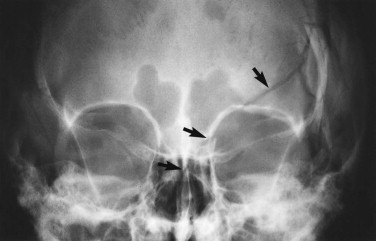
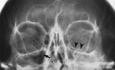
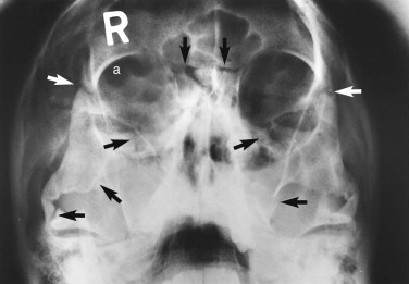
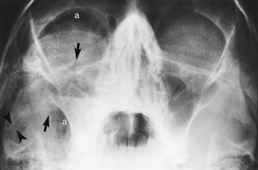
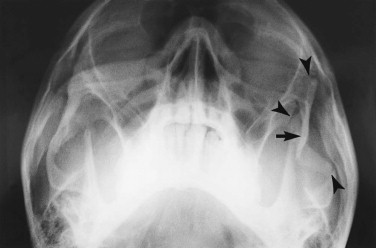
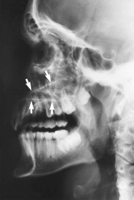
For reasons of classification and convenience, the face is often divided into upper, middle, and lower thirds, and the middle third is further divided into central and lateral components. Suspected fractures of the upper third of the face require a Caldwell projection ( Fig. 5-1 ) or, preferably, a modified Caldwell’s view ( Fig. 5-2 ) and a lateral projection. Middle-third injuries require occipitomental 10-degree ( Figs 5-3 and 5-4 ) and 30-degree ( Fig. 5-5 ) views, which can be supplemented by a lateral projection if the central middle third is involved ( Fig. 5-6 ). Lower-third injuries require a posteroanterior (PA) mandible view and panoramic tomography (OPG) or, if the latter is not available, lateral oblique views of both sides (see “ Radiography of Facial Injuries ”). These views should be taken with the patient erect whenever possible, not only for comfort but to show fluid levels in the sinuses. Such plain film views may not be necessary if CT has been or needs to be done on an emergency basis or if there are adequate radiographs available from a primary referring hospital. Other projections (see “ Radiography of Facial Injuries ”) are rarely needed.
Computed Tomography
CT has almost entirely supplanted nonpanoramic tomography. It has the advantage of providing multiplanar thin-slice images of the facial skeleton, overcoming the problem of superimposition of structures that inevitably occurs on plain radiographs. The newest generation of multidetector CT scanners (MDCT) are able to acquire data very rapidly. Slice information obtained in one plane can be reconstructed to provide images in alternative planes, if such alternative image planes are not obtainable directly.
A small field of view should be used, and the scanning should be performed with a high-resolution bone algorithm. Soft tissue windows can then be obtained from this original dataset. Generally, a slice thickness of 2 to 4 mm is adequate in assessing facial trauma and has the advantage that the examination is faster than when thinner slices are acquired. However, if reformatting is needed, very thin slices are required: 1-mm axial slices should be obtained with subsequent coronal reformats. Sagittal reformats are not commonly required for facial imaging, and obtaining thinner axial slices, although technically possible, yields no significant improvement in resolution.
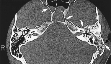
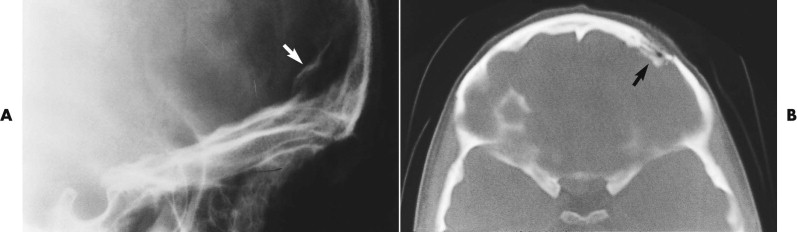
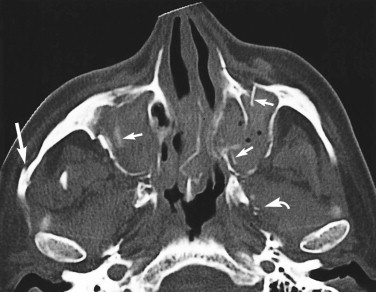
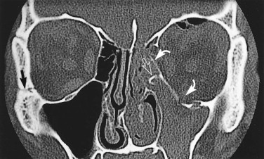
In almost every case coming to CT scanning, axial-slice images are obtained ( Figs. 5-7 through 5-9 ). The standard position for axial (transverse) slices is with the slice plane parallel to the anthropological baseline. This position is easy for the patient, and landmarks are easy to identify on the initial scanogram view. However, CT scanning protocols vary considerably with clinical circumstances. Coronal images are particularly helpful in orbital examination ( Fig. 5-10 ) but are also useful in other situations. Coronal imaging has the benefit of visualizing the horizontal struts or plates of bone, which in standard axial slices lie parallel to the slice plane and therefore are poorly visualized. Such horizontal plates include the orbital roof, cribriform plate, orbital floor, and hard palate.
Direct coronal imaging is ideally performed in the true coronal plane, but two factors may require the gantry angle to be adjusted. First, many patients, particularly the elderly and those with a rigid spine, may not be able to extend their neck sufficiently. Indeed, in some patients, direct coronal scanning cannot be done at all (or, if the cervical spine is still under suspicion, should not be done). Second, dental amalgam and other fixed prosthodontic devices can produce serious streak-like artifacts that seriously diminish image quality.
Three-dimensional (3-D) datasets have become increasingly requested since the advent of navigational surgical techniques. These new approaches to surgery require CT information to accurately direct the navigational equipment. Early published data from navigational surgery centers suggest these techniques confer improved functional and aesthetic results with reduced operating times.
With the advent of digital image storage and Picture Archiving and Communication Systems (PACS), CT images are now routinely assessed on the computer rather than on the cut film of old. This has several advantages, because the software associated with the viewing computers allows for image manipulation (e.g., magnification) and direct calibrated measurement.
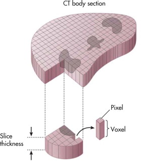
When a CT is performed, the scanner ascribes a unit measurement to a 3-D pixel, called a voxel, that is representative of a portion of the area scanned. Many voxels make up an image ( Fig. 5-11 ). The unit measurement ascribed is known as a Hounsfield unit and relates to the density of the tissue in that small area. The values of these measurements range from −1000 (fat) to more than +1000 (bone). If this range of values were translated directly into a gray scale, the human eye would not be able to differentiate all shades of gray from each other, and critical information would be lost. To allow complete assessment of the range of tissue densities, the viewing systems allow users to “window” the data. Based on a selection from the user, the computer sets a density middle value and a viewable range that the eye can appreciate. These settings allow certain tissues (e.g., bone, lung, brain) to be completely assessed according to the known density ranges they contain. It is critical to be aware of windowing and how to adjust the windows when assessing CT images so that image data are not missed ( Fig. 5-12 ).
Stay updated, free dental videos. Join our Telegram channel
VIDEdental - Online dental courses


