The location of certain bony landmarks is important in the planning stage as well. These include the proximity of the floor of the nose in the anterior maxilla, prominent maxillary incisive foramen or mandibular genial tubercles, or a more anteriorly positioned maxillary antrum for a maxillary canine or first premolar clinical situation. Modification of the surgical plan may become necessary based on the findings on the scan.
Additionally, any pathology found on the scan must be identified and factored into treatment. If the clinician does not feel she/he has the expertise to fully interpret image data, it should be referred to a specialist.
Anything that is identified on the scan that may alter or modify the treatment plan must be discussed by all members of the treatment team as well as with the patient. This may involve simple changes (such as from screw to cement retention for the crown), or much more significant modifications (such as a change in the number of or location of fixtures as well as preimplant reconstructive procedures).
Treatment planning
Treatment planning includes the number of teeth that will be replaced, the number and location of implant fixtures (determined by the scan results), whether site development is required and what type of procedures are necessary to achieve this (determined from both the clinical examination and the radiographic assessment), whether teeth will be removed, if fixture(s) will be placed immediately or delayed and if the restoration will be screw-retained or cemented.
Radiographic/surgical G
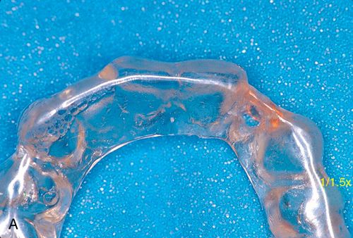
A properly designed guide stent is often crucial for esthetic situations. The stent should be anatomically correct and represent the size, shape, and position of the planned restoration. The stent can be made of hard acrylic (such as a night guard designed with pontics) or with rigid tray material (formed on a wax-up of the case) (Fig. 16-2 A). (See the section on Stents in Chapter 17). When there is a posterior edentulous distal extension, the stent should be secured on the adjacent teeth anterior to the planned implant site(s). For cases with only posterior teeth in one sextant (anterior and unilateral posterior edentulous ridge), the stent must extend far enough posteriorly on the edentulous side so it rests on the crestal gingiva beyond the extent of the incision. Often the stent will serve a dual role, being both a radiographic and surgical guide
When used during scanning, radiopaque markers are placed to show the location of the planned restoration in relation to the underlying bone. If a single tooth is being replaced, then markers are put on the stent in that location only. If multiple teeth are missing, then the markers need to be placed for each tooth in the restoration regardless of how many fixtures are considered, thus allowing for identification of the most ideal sites.
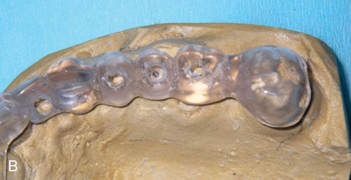
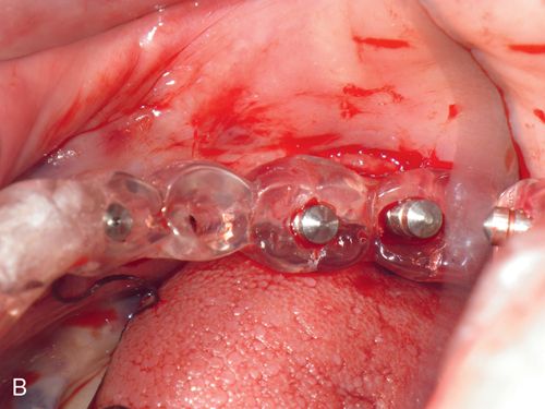
Marking the stent can be achieved in different ways. A radiopaque material can be applied on the surface of the teeth on the stent (such as barium powder or a piece of lead foil from a conventional x-ray film) which will provide an outline of the planned restoration on the scan image. Another method is to place a 2- to 3-mm diameter hole in the center of the occlusal table (for posterior teeth) or cingulum (for anterior teeth) to mimic the screw access hole of the fixture (Fig. 16-2 B).
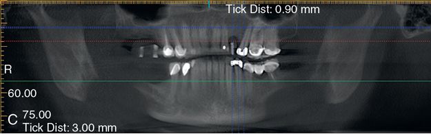
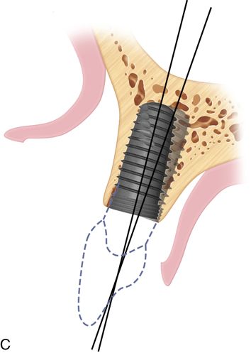
The hole in the stent is filled with gutta percha that will be displayed radiographically as a white vertical line over the scanned ridge (Fig. 16-2 C). In both instances, the markers will allow the surgeon and restorative dentist to see the location of the bone in relation to the planned restoration.
With this information the surgeon can relay to the restorative team member the size options for the fixture, such as length and diameter ranges, and the location the fixture can occupy in the ridge. This also allows the restorative dentist to convey a fixture location preference. In the case of multiple fixtures, this information can be used to identify the best location for the fixtures supporting the restoration. At this time the stent can be adjusted to represent the endpoint of this collaboration. Repositioning of the guide hole of the radiographic stent can be accomplished, thus converting it into the surgical stent.
Gathering as much initial pertinent information as possible and maintaining good communication between all team members can eliminate most, if not all, potential future problems.
Surgical planning
Surgical treatment planning the single tooth case may appear to be quite simple. However, the basic principles of surgical preparation and placement apply regardless of the number of implant fixtures that will be placed. The single implant situation is unique because there are usually two natural teeth adjacent to the fixture location and the relationship between the position of the fixture and the interdental bone between the approximating teeth is critical to the outcome of treatment.
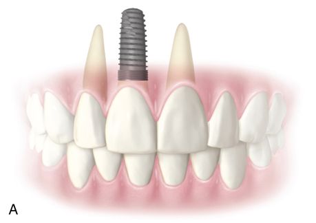
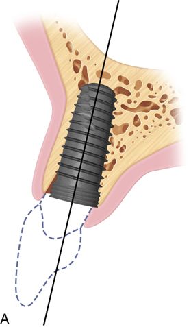
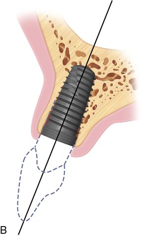
One of the major esthetic challenges is the creation of a normal peri-implant gingival complex mimicking that of a natural tooth. The fixture platform must be positioned sufficiently apical to allow formation of a proper restoration subgingival emergence profile. In the non-periodontally involved case (no crestal bone loss) this requires the platform to be at least 2 to 3 mm apical to the level of the facial cementoenamel junction (CEJ) of the adjacent teeth (Fig. 16-3 A). In a restored dentition, the facial restoration margins (crowns, veneers, etc.) of the adjacent teeth are used as the landmark instead of the CEJ. If restoration of the adjacent teeth is anticipated, the final position of the soft tissue margins need to be determined (with provisional restorations or a diagnostic wax-up) before fixture placement. These guidelines apply to implants placed into a healed edentulous ridge or for immediate placement at time of extraction. When immediate placement is performed, the platform will be apical to the interproximal bone height, and radiographically this will show the implant platform being apical to the interproximal bone (Fig. 16-3 B). Therefore only hard tissue landmarks can be used when assessing platform position radiographically. Clinical observation is needed to assess platform position in relation to the soft tissue margins.
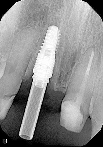
When the diameter of the fixture is less than that of the tooth root that was extracted, this apical placement is necessary in order to create a natural sub-gingival flare (emergence profile) which will mimic the shape of a natural tooth. Without this submarginal space, it may be impossible for the dental laboratory to provide a naturally appearing crown. If the platform is positioned too coronally, there is also a risk that the crown-fixture interface could become visible.
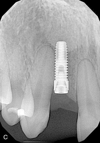
Violation of the periodontal ligament space of an adjacent tooth would result in damage to the natural dentition as well as create a fixture-to-periodontal ligament (PDL) fiber contact. The latter would interfere with osseointegration and result in fibroencapsulation of the implant (Fig. 16-3 C) placed too close to the adjacent canine violating the PDL space. The fixture ultimately failed.
In addition, if the platform is too close to the approximating teeth, there will be insufficient lateral space to create the appropriate tooth shape.
The center of the fixture should be palatal to the position of the incisal edge or at the cingulum (the buccolingual dimension) of the final planned restoration. For proper surgical healing sufficient thickness of the buccal plate is required in order to maintain the integrity of the facial crest. The closer the fixture is positioned to the buccal plate, the greater the likelihood of a dehiscence and apical shrinkage of the soft tissues. Improperly angled placement could also result in perforation of the facial plate, with the fixture apex being beyond the confines of the bony housing.
Palatal positioning is a necessity for the screw-retained restoration. The long axis of the implant must provide sufficient space for the laboratory to add material to the body and incisal edge of the restoration while leaving adequate space for the insertion of driver tips within the screw access hole (Fig. 16-4 A).
The angulation of insertion of the fixture is also crucial for the screw retained restoration. Using the platform level as the fulcrum of rotation, the angle of insertion can affect the type of retention for the restoration.
If a cement retained restoration is planned, the long axis of the screw path should be no farther facial than the incisal edge to allow for proper abutment design (Fig. 16-4 B). With this type of restoration, more flexibility is present regarding platform positioning. The long axis of the fixture should ideally be in line with the incisal edge of the planned restoration.
The angulation of insertion of the fixture is also crucial for the screw retained restoration. Using the platform level as the fulcrum of rotation, the angle of insertion can affect the type of retention for the restoration (Fig. 16-4 C). If the platform is positioned too far buccally, then the proper height of contour and emergence profile of the restoration cannot be achieved regardless of whether the restoration is screw or cement retained.
The maintenance or creation of interdental papillae and avoiding “black triangles” is one of the most crucial aspects of success in the esthetic zone. To achieve this requires an understanding of the biology as it applies to both the surgical and prosthetic aspects of single tooth replacement.
The fixture must have proper 3-D placement (particularly occlusoapically and mesiodistally) to allow the restorative dentist to create proper restoration contours to support the papilla.
Clinical case: Maintaining the papillae
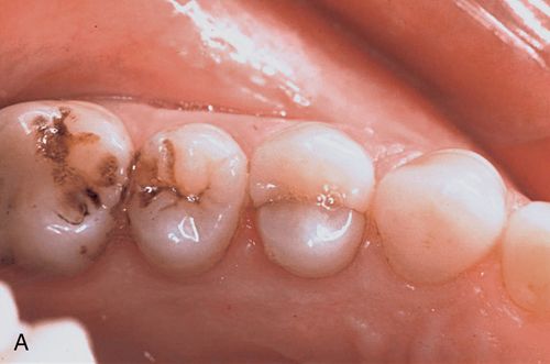
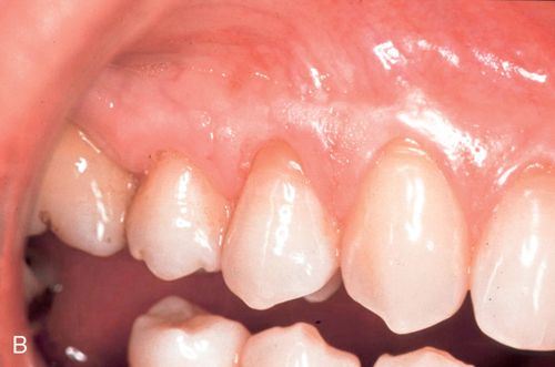
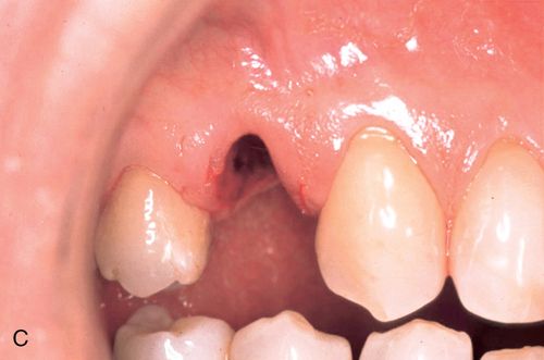
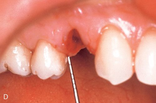
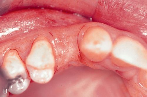
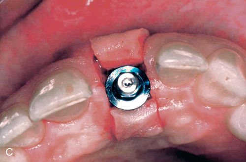
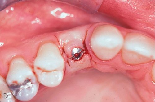
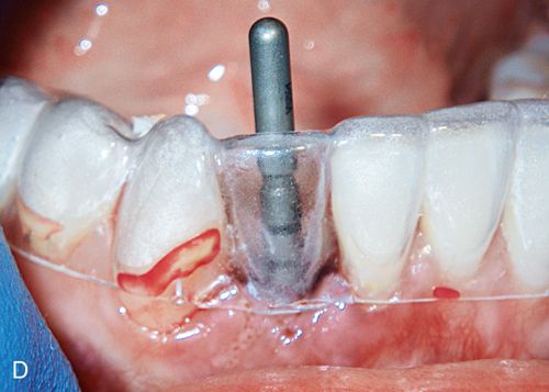
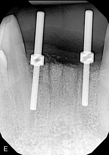
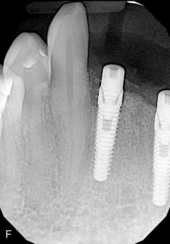
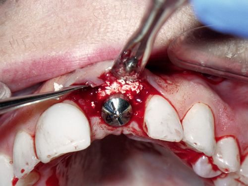
A 33-year old woman presented with a fractured maxillary right first premolar (Fig. 16-5 A,B) that was not restorable. After atraumatic extraction (Fig. 16-5 C), fixture placement the site revealed an intact socket with good interproximal crestal bone (Fig. 16-5 D).
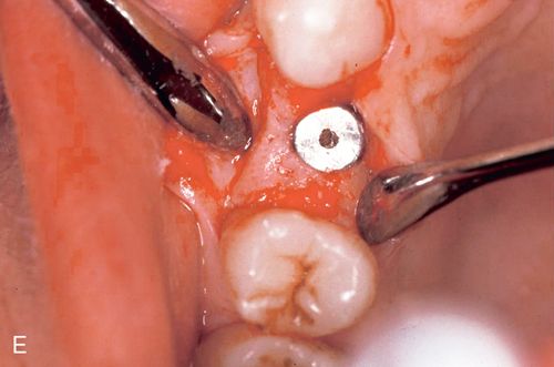
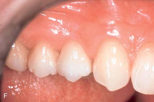
An immediate implant fixture was placed and after healing (Fig. 16-5 E) and provisionalization (Fig. 16-5 F), an excellent soft tissue result was achieved.
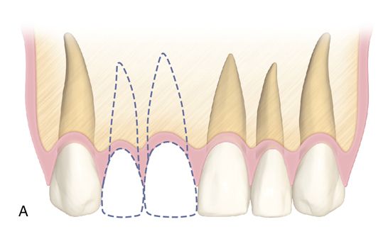
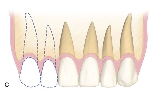
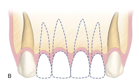
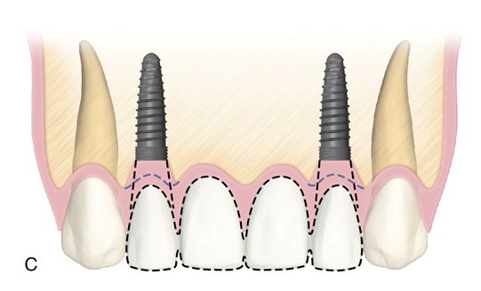
The same considerations regarding single tooth implants apply to multiple tooth edentulous areas; however, there are additional factors to consider other than the volume of bone. From the soft tissue standpoint, when single implants are placed between two teeth, the bone and PDL fibers on the natural tooth determine papilla position. When placing two adjacent implants, this is no longer the case. Without the root surface and PDL fibers to maintain bone height, the interimplant bone is more prone to resorption and cannot support the soft tissues. For the low esthetic risk patient (low lip line, thick, flat gingival biotype and/or wide alveolar ridge mesiodistally) or a patient without any cosmetic expectations, placing individual fixtures could be acceptable. Many patients present with a thinner, scalloped gingival biotype with considerable esthetic display of gingiva, whereby placement of a fixture to replace each missing tooth runs a higher risk of failing to achieve esthetic expectations.
The minimum distance requirements are slightly different when placing adjacent fixtures as compared with a single fixture. Although the 1.5 mm distance requirement from the adjacent teeth does not change, there must be at least 3 mm between each fixture (discussed below) in order to maintain bone and tissue height. This effectively increases the amount of mesiodistal edentulous ridge length necessary to successfully place individual fixtures for a cosmetic end result. This concept applies to placement in the immediate socket as well as the healed ridge. These situations occur most often in the maxillary lateral incisor positions as well as with all mandibular incisors, where the size of the teeth and the amount of interradicular bone is typically narrow. In the case of the mandibular incisors, avoiding adjacent fixture placement often becomes a functional necessity (e.g., lack of adequate mesiodistal length to place two fixtures), but the esthetic considerations still apply.
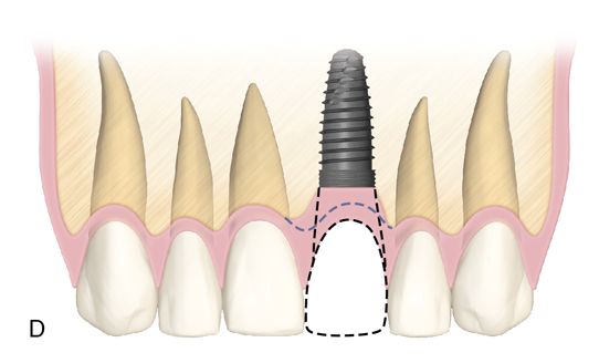
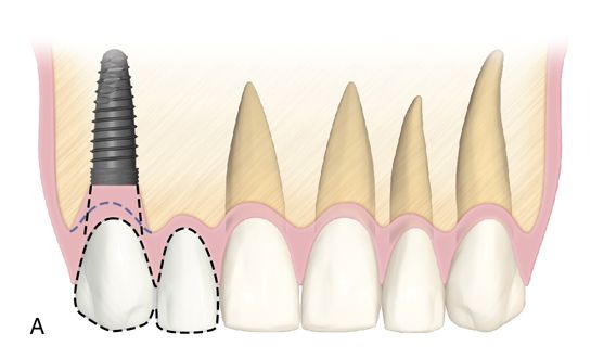
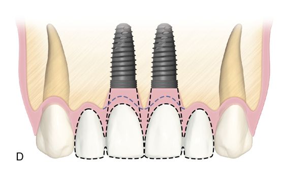
When there is sufficient edentulous span length and adequate bone volume in the two tooth span, then individual fixture placement can be considered, with the most common situation being two missing maxillary central incisors. Where narrower mesiodistal restorative space exists (as described previously), placing adjacent fixtures should be avoided whenever possible, particularly in the anterior maxilla. When a two tooth edentulous space is treated, it is preferable to place a single fixture for the larger of the two teeth being replaced (such as the central incisor/lateral incisor or canine/lateral incisor situation) with the final restoration, being an implant-supported two-unit cantilevered bridge (Fig. 16-6). This provides a better ability to manipulate the soft tissue (e.g., papillae and facial gingiva) and minimize the negative effects adjacent fixtures have on the soft tissue frame.
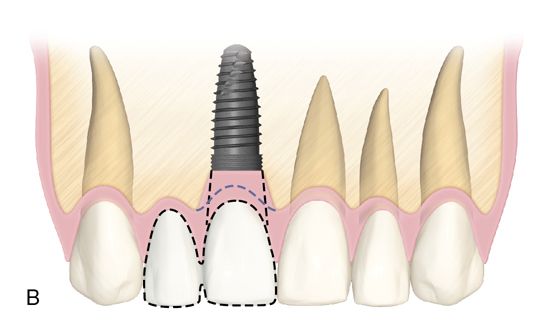
Treating a two tooth span with one fixture provides more restorative flexibility, particularly with soft tissue considerations. The absence of a second fixture eliminates constraints on the shape of the pontic. Emergence contours (buccolingually and mesiodistally) and interproximal contact area location and length can be manipulated to maximize the esthetic results. Ovate pontics can create the illusion of a papilla more predictably than when two fixtures are placed in adjacent tooth locations.
When developing ovate pontic form in the immediate extraction case, the apical portion of the pontic must extend into the extraction socket beyond the soft tissue margin by approximately 2 to 3 mm. This will allow circumferential healing around the bullet-shaped underside of the pontic. Care must be taken that the restoration does not extend beyond 3 mm. into the socket, which will interfere with proper healing. This type of soft tissue development can be performed whether or not the site is grafted. As the gingiva matures, modifications of the provisional restoration can be performed to guide the healing as needed; material can be added or subtracted depending upon the needs of the individual situation. This is especially helpful when performing immediate provisionalization in cases demonstrating a thin, scalloped gingival biotype.
If implant placement is performed in the healed edentulous ridge, conventional ovate pontic preparation (as described in Chapter 14) should be accomplished. Adequate volume and dimension of keratinized soft tissue (height and width) must exist at the ovate pontic site in order to reasonably consider this option. The ovate pontic preparation must be neither too shallow nor too deep. Underpreparation can result in flattening of the tissue profile with exposure of the underside of the pontic. Overpreparation can result in an uncleansible pontic area or cause pressure necrosis with both soft tissue and bone loss. Making a 2- to 3-mm deep preparation into the gingival connective tissue of the pontic site is appropriate. As with immediate placement situations, modification of the underside of the pontic can be performed at any time to guide the desired soft tissue healing. The patient should remain with a provisional restoration in place until full healing has occurred (minimum of 8 weeks) before proceeding to the definitive restoration.
The practice of using a cantilever as part of any implant supported prosthesis is usually discouraged because of the off-axis forces that are placed on the restoration. This is true for a posterior case where the forces of mastication are stronger. Even vertically directed force on a cantilever can create an eccentric vector on the fixture/abutment interface. However, in the anterior dentition the strength and direction of forces differ from that in the posterior region which allows the use of cantilevers in certain situations. In the mandible, either the central or lateral incisor site can be considered, though only the lateral incisor site in the maxilla is a good candidate. Contact in maximal intercuspal position on the pontic from the opposing arch must be lighter than on the adjacent anterior teeth and implant. Lateral and protrusive excursive movements must be on the natural teeth and implants, with minimal to no contact on the pontic. The use of an occlusal appliance is also highly recommended to control nocturnal parafunction. Situations in which cantilevers would be contraindicated include patients with severe parafunctional habits (even if an appliance is used), those with a deeper bite greater than 50%) or with anterior malocclusion (Class II – Division 2 or Class III relationships), severe crowding, and/or rotation.
For the three and four tooth spans, placing a single fixture next to the adjacent teeth and restoring as a three or four unit implant-supported bridge is preferred over replacing each tooth position with a separate implant. Good papilla form can be maintained or created in the presence of adequate bone on the adjacent natural teeth and by using ovate pontics (Fig. 16-7).
Another option for replacing four missing maxillary incisors is the placement of two central incisor fixtures with two lateral incisor pontics. This is preferred when the bone volume is greater in the central incisor locations as opposed to the lateral incisor locations or if there is a deficiency at the lateral incisor sites.
If the need arises to place two adjacent implants, there must be at least 3 mm between fixtures in order to preserve the crestal bone, which in turn supports the papilla (note that this is different than the 1.5-mm minimum distance between implants and adjacent teeth). Even if some bone remodeling occurs around the restorative platform of the fixture, interproximal crestal loss is kept to a minimum if the correct distance between fixtures is satisfied, Fixtures placed too close to each other will result in horizontal crestal resorption, which will lead to a flat gingival profile without creating the desired scalloped architecture. Slight subcrestal placement can be considered to create a higher interfixture peak of bone to support a papilla.
Surgical placement
Flap design
The placement of incisions for implants in the esthetic zone should provide adequate access to perform the procedure and be as conservative as possible so as not to create changes in the tissue architecture of the implant site and the adjacent teeth. Obviously, adequate reflection of the tissues is required to assure proper positioning as well as provide the ability to perform any adjunctive procedures (such as bone and/or soft tissue grafting at the time of placement). Presurgical planning is crucial (see the sections on diagnosis, treatment planning, and surgical planning earlier in this chapter).
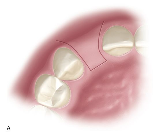
When adequate buccolingual width of the ridge exists, a papillae preserving incision design should be employed, particularly in the maxillary esthetic zone. Two vertical incisions are placed at the base of the adjacent papilla and connected with a horizontal incision paracrestally (toward the palate). The buccal extent of the vertical incisions will be predicated upon the amount of reflection that is necessary for placement of the fixture (Fig. 16-9 A,B).
If the incision must be extended buccally near or beyond the mucogingival junction, there should be slight divergence apically. If the base of the flap is wide, the blood supply is not compromised. Once placed, the fixture can either be buried (two-stage approach) or a healing abutment or provisional restoration can be attached (one-stage approach) (Fig. 16-9 C,D).
Minor mucogingival issues can often be corrected at the time of placement with buccal positioning of the flap if adequate reflection is achieved.
If full access to the edentulous ridge is required, the entire body of the papilla should be included in the buccal flap using the paracrestal incision design (Fig. 16-10 A). Vertical incisions for this approach should be kept to a minimum. If placed, they should be at the line angles of the teeth adjacent to the implant site to provide access. If significant buccal reflection is needed, conservative vertical releases can be performed away from the implant site or an envelope flap design can be used. With either choice, buccal access is achieved while maintaining the blood supply and integrity of the papillae that have been included in the flap. Using these types of incision designs, a two-stage procedure should be performed and the flap should be replaced to its original position covering the fixture. The papillae-preserving flap design (discussed earlier in this section) can be used when uncovering the fixtures after integration.

Implant fixture placement
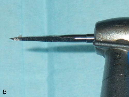
The contours of the anterior ridge receiving a fixture will often have a rounded profile as opposed to the flatter, plateau-type appearance of a posterior ridge. Assuming adequate width of bone is present to place the fixture; this type of ridge shape does not preclude implantation, but presents the challenge of ensuring that the initial pilot preparation is properly positioned. Using a precision point twist drill or a small round burr allows the creation of a small pilot hole or dimple in the ridge, thus providing the surgeon with a positive seating location to begin the drilling sequence (Fig. 16-10 B). If an initial twist drill (typically 2 mm in diameter) were to be used first, the tip can sometimes move or “skip” on the surface of the ridge. If a positive entry point is made, this occurrence is minimized. A stent is used for this initial osteotomy preparation, with the drills placed directly through the guide hole.
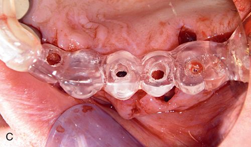
During surgery, the stent guides the placement of the initial osteotomy preparation in the edentulous ridge. The stent must be secure on the adjacent teeth in order to provide for accurate placement of the osteotomy (Fig. 16-10 C).
When designed properly the stent allows for accurate positioning of the fixture in both the buccolingual and mesiodistal dimensions, all of which were predetermined in the planning phase. Use of the stent to confirm proper positioning when widening the osteotomy site should be accomplished by checking the angulation using surgical guide pins (Fig. 16-10 D).
With proper initial placement, minor angulation differences with subsequently larger diameter twist drills can occur. By using the stent in this manner, the surgeon can insure proper placement. This is particularly important when placing more than one fixture because the greater the distance between implants, the greater the chance that buccolingual and mesiodistal errors can occur.
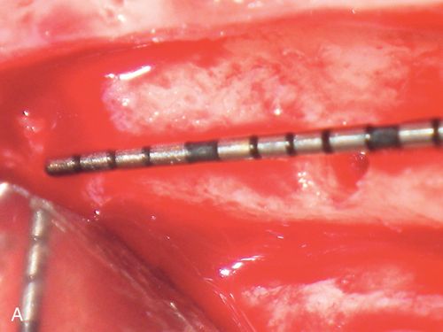
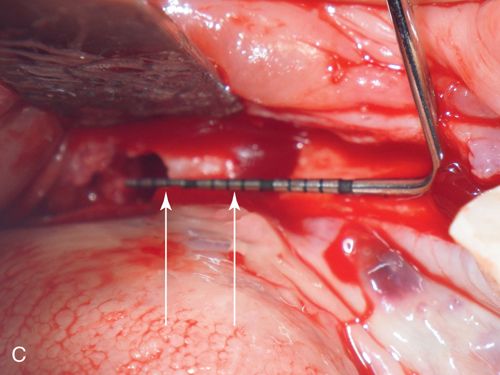
A check radiograph should be taken to ensure that the direction of the initial osteotomy is correct in the body of the alveolar bone. Surgical guide pins can be placed into the osteotomy site positioned through the access hole in the stent, with a radiograph showing the angulation in relation to the adjacent roots of the natural dentition. The osteotomy preparation should be equidistant from the adjacent roots on the surface and not converge too closely to either of the roots as the site is prepared apically to avoid violating the 1.5-mm root-implant minimum distance requirement. Before enlargement of the osteotomy any correction should be made so as to avoid buccal or lingual plate perforation as well as violation of the implant/tooth or implant/-implant distance requirements (Figs. 16-10 E,F).
The final osteotomy site should leave at least 1.5 mm of interproximal bone between the fixture and each of the roots of the two adjacent teeth (or 3.0 mm of bone between adjacent implants), maintain approximately 1.5 mm of intact facial and lingual/palatal plate of bone and have proper platform positioning, as described earlier, in an apical location in relation to the adjacent teeth. Platform height should be assessed as the osteotomy is enlarged with increased diameter drills because as an osteotomy site is widened, the height of the buccal or lingual crest may move apically (many anterior ridges are rounded and not flat). It may be necessary to use a shorter fixture or deepen the preparation if this occurs.
Surgical site closure
Closure of the surgical site will be predicated upon how the internal screw access of the implant is covered. If a cover screw or internal closure screw is placed, then primary closure is preferable. Proceeding in this manner will require a second stage uncovering procedure once the fixture has integrated. Regardless of the reason for performing a two-stage approach (such as minor grafting of the site), any endeavors toward guiding the soft tissue emergence profile must be performed at the second stage. If the patient has a transitional restoration, whether fixed (resin bonded bridge or acrylic provisional bridge) or removable (“flipper”), relief of the pontic tooth is necessary in order to avoid pressure on the flaps.
When primary closure is not necessary, closure of the surgical site should attempt to create the desired soft tissue profile in preparation for the final restoration whenever possible. This can be accomplished with a healing abutment or provisional crown. An immediately placed provisional crown should exactly mimic the contours of the definitive restoration and guide soft tissue healing. Once adequate stability of the implant occurs (approximately 6 weeks), the provisional restoration can be removed and the shape adjusted if needed.
If a healing abutment is used, the contours should approximate those of the final restoration, taking into account the selections available from each implant manufacturer. Both methods can be used even when minor bone grafting is performed (Fig. 16-11).
When securing the provisional crown, it is crucial that light force is used with a hand driver when tightening the abutment screw while simultaneously holding the crown/implant unit with finger stabilization. Even though the fixture may seem extremely stable, it is purely a mechanical phenomenon. Using a torque driver or heavy finger pressure at this point could cause eccentric force to be applied to the fixture and could possibly interfere with successful osseointegration. Using light force at initial placement will also allow for easier removal of the provisional restoration when making any modifications or changes that may be desired after the initial 6 weeks of healing.
If vertical incisions are placed beyond the mucogingival junction or an envelope flap is extended laterally, buccal positioning of the flap is possible, with the abutment maintaining this surgical augmentation The height of the abutment must be considered if a transitional restoration is being used because it could interfere with full seating. Relining of a removable appliance or adjustment of a fixed provisional restoration must be accomplished post placement. A limiting factor with healing abutments is that they have a round profile (less of a factor for incisors). However, by placing a provisional restoration after healing, any minor discrepancies are easily corrected.
Clinical case: Single tooth with soft tissue guidance
A 29-year-old man presented for a single implant in the maxillary right central incisor position. Adequate bone volume of the edentulous ridge was present for implant placement, but there was a sloping deficit of the facial gingiva (Fig. 16-12 A). Papillae-sparing incisions were made and the flap was reflected (Fig. 16-12 B).
Stay updated, free dental videos. Join our Telegram channel
VIDEdental - Online dental courses


