Diagnostic Imaging for the Implant Patient
Several radiographic imaging options are available for diagnosis and treatment planning of patients receiving dental implants.2,17,18 Options range from standard projections routinely available in the dental office to more complex radiographic techniques typically available only in radiology centers. Standard projections include intraoral (periapical, occlusal) and extraoral (panoramic, lateral cephalometric) radiographs. More complex imaging techniques include cone-beam computed tomography (CBCT) and multislice computed tomography (MSCT). The CBCT and MSCT image data files can be reformatted and viewed on a personal computer using simulation software, making the diagnosis and treatment-planning process interactive and visually more meaningful. Often, combinations of various modalities are used because no single modality can provide all information pertinent to the radiographic evaluation of the implant patient. Familiarity with the benefits and limitations of various techniques and awareness of the specific clinical questions that need to be answered should guide the decision-making process and selection of radiographic examinations for individual patients.
Standard Projections
Standard diagnostic imaging modalities include periapical, panoramic, lateral cephalometric, and occlusal radiographs. Table 73-1 summarizes the advantages and disadvantages of each modality.
TABLE 73-1
Advantages and Disadvantages of the Various Radiographic Projections
| Modality | Advantages | Disadvantages |
| Periapical and occlusal radiography | High resolution and detail, easy acquisition, low exposure, inexpensive | Unpredictable magnification, small imaged area, 2D representation of anatomy |
| Panoramic radiography | Easy to acquire, images whole ridge, low exposure, inexpensive | Unpredictable magnification, unequal magnification in vertical and horizontal dimensions, 2D representation of anatomy, not detailed |
| Lateral cephalometric radiography | Easy to acquire, predictable magnification, low exposure, inexpensive | Limited use in area of midline, 2D representation of anatomy |
| Multislice computed tomography | 3D representation, predictable magnification, sufficient detail, digital format, images whole arch | Requires special equipment, expensive, high-exposure dose |
| Cone-beam computed tomography | 3D representation, predictable magnification, sufficient detail, digital format, images whole arch, low dose | Requires special equipment, expensive |
Periapical Radiographs
Periapical radiographs offer great advantages to evaluate the implant patient.19,20 They provide an overall assessment of the quantity and quality of the edentulous alveolar ridge and the adjacent teeth. They are easy to obtain in the dental office, are inexpensive, and deliver low radiation to the patient (Table 73-2). Dentists are familiar with the depicted anatomy and possible pathology. Because these direct-exposure projections do not use intensifying screens, intraoral radiographs offer the highest detail and spatial resolution of all radiographic modalities (Figure 73-1). Thus, intraoral radiographs are the projection of choice when subtle pathology, such as a retained root tip, needs to be detected and evaluated.
TABLE 73-2
Radiation Dose (Effective Dose in µSv) Received from Common Projections During Evaluation of the Implant Patient Data*
| Modality | Effective Dose (µSv) |
| Full-mouth x-ray (FMX) series | 35-388 |
| Panoramic | 9-26 |
| Conventional tomography | 26-187 |
| CT of the head | 2000 |
| Large field-of-view CBCT | |
| NewTom 3G | 30-68 |
| i-CAT: next generation portrait mode | 74-83 |
| Kodak 9500, 20 cm × 18 cm | 93-260 |
| Galileos Comfort, 15 cm × 15 cm | 70-128 |
| Scanora 3D, 14.5 cm × 13.5 cm | 68 |
| CB Mercuray, 20 cm diameter | 569-1073 |
| Medium field-of-view CBCT | |
| Accuitomo 170, 10 cm × 5 cm | 54 |
| iCat next generation, 16 cm × 6 cm | 45 |
| iCat, classic, 16 cm × 8 cm | 34-77 |
| NewTom 3G, 10 cm diameter | 57 |
| Kodak 9500, 15 cm × 8 cm | 76-166 |
| Prexion, 8 cm × 8 cm, low dose | 189 |
| Prexion, 8 cm × 8 cm, high dose | 389 |
| Promax 3D, low dose | 28 |
| Promax 3D, high dose | 122-652 |
| Small field-of-view CBCT | |
| Accuitomo 3DX, 4 cm × 4 cm | 13-44 |
| Kodak 9000, 5 cm × 3.7 cm | 19-40 |
| Pax Uni-3D | 44 |
CT, Computed tomography; CBCT, cone-beam computed tomography.
*Reviewed by Ludlow JB, Davies-Ludlow LE, White SC: Patient risk related to common dental radiographic examinations: The impact of 2007 International Commission on Radiological Protection recommendations regarding dose calculation, J Am Dent Assoc 139:1237, 2008; Ludlow JB, Ivanonic M: Comparative dosimetry of dental CBCT devices and 64-slice CT for oral and maxillofacial radiology, Oral Surg Oral Med Oral Pathol Oral Radiol Endod 106:106, 2008; and White SC, Mallya SM. Update on the biological effects of ionizing radiation, relative dose factors and radiation hygiene. Aust Dent J 57(Suppl 1):2, 2012.
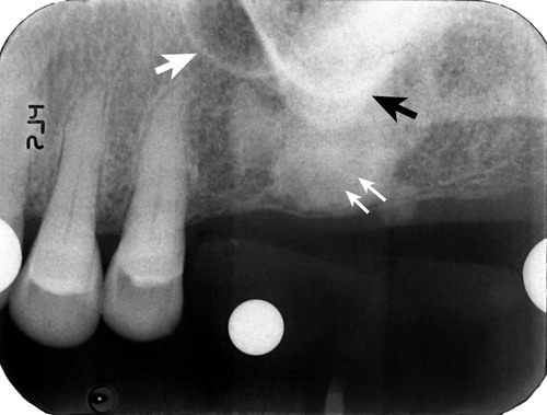
Healing of the extraction socket with dense bone (socket sclerosis) can be seen (small white arrows). Some anatomic structures, such as the maxillary sinus (large white arrow) and the zygomatic process of the maxilla (black arrow), can also be visualized.
The most significant disadvantage of periapical radiographs is their susceptibility to unpredictable magnification of anatomic structures, which does not allow reliable measurements.15 Foreshortening or elongation can be minimized by the use of paralleling technique. However, distortion is particularly accentuated in edentulous areas, where missing teeth and resorption of the alveolus necessitate receptor placement at significant angulation in relation to the long axis of the teeth and alveolar bone. Additionally, periapical radiographs are two-dimensional representations of three-dimensional objects and do not provide any information of the buccal–lingual dimension of the alveolar ridge. Structures that are distinctly separated in the buccal–lingual dimension appear to be overlapping. Also, the periapical image is limited by the size of film or sensor being used. Often, it is not possible to image the entire height of the remaining alveolar ridge, and when extensive mesial–distal areas need to be evaluated, multiple periapical radiographs are required.
Occlusal Radiographs
Occlusal radiographs are intraoral projections that offer easy, economic, low-dose, and high-resolution images covering a larger area than periapical projections.20 Depending on receptor placement and the angulation of the x-ray tube, occlusal radiographs can provide an image of the mandibular width or can depict an extended area of the edentulous ridge. Occlusal radiographs have the same limitations of distortion and overlapping anatomy as periapical radiographs.
Panoramic Radiographs
Panoramic radiographs are often used in the evaluation of the implant patient because they offer several advantages over other modalities.16 Panoramic radiographs deliver low radiation (see Table 73-2) to provide a broad picture of both arches and thus allow assessment of extensive edentulous areas, angulation of existing teeth and occlusal plane, and important anatomy in implant treatment planning such as the maxillary sinus, nasal cavity, mental foramen, and mandibular canal (Figure 73-2). Panoramic units are widely available and easy to operate, and dentists are familiar with the anatomy and pathology depicted by the images. Similar to intraoral projections, panoramic images are two-dimensional and thus do not offer diagnostic information for the buccal–lingual width of the alveolar arch.
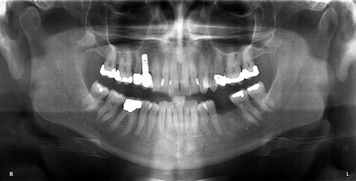
Both jaws are visualized on the same image. An overall assessment of superoinferior and mesial-distal dimensions of the alveolar ridge can be formulated. Tooth and root positions relative to planned implant sites can be evaluated. Important anatomic structures, such as the maxillary sinus and mandibular canal, can be identified.
Panoramic images appear intuitively familiar. However, they combine characteristic physical and radiographic principles that make them distinct from other intraoral and extraoral radiographs. Although outside the scope of this chapter, familiarity with the principles underlying panoramic radiography is central in understanding, and thus compensating for, the limitations and constraints of the images. The reader is referred to other textbooks for detailed discussion of this topic.7,10 Briefly, the existence of ghost shadows, unpredictable horizontal and vertical magnification, distortion of structures outside the focal trough, projection geometry generated by the negative vertical angulation of the x-ray beam, and propensity to patient-positioning errors do not allow consistently detailed and accurate measurements to be generated. As a result, panoramic radiographs do not provide the highly detailed images that are generated by intraoral radiographs.
Lateral Cephalometric Radiographs
Lateral cephalometric radiographs are occasionally used to evaluate potential implant patients.17 These projections provide useful information for the cortical thickness, height, and width of the alveolar ridge at the midline, as well as the skeletal relationship between maxilla and mandible and facial profile. Lateral cephalometric radiographs are low in cost, readily available, and easy to interpret, and have a predictable magnification of the depicted structures. However, their use for the implant patient is limited to structures at the midline, with minimal usefulness for other areas of the jaws.
In summary, lateral cephalometric radiographs have a limited use in implant treatment planning.
Cross-Sectional Imaging
Multislice Computed Tomography
CT scanning is widely used in the evaluation of the implant patient.3,6 The detailed physics behind image acquisition during CT scanning are beyond the scope of this chapter.4 In general, a fan-beam of x-rays and an array of detectors rotate around the patient to generate axial slices of the area of interest (Figure 73-3, A). Multiple overlapping axial slices are obtained by several revolutions of the x-ray beam until the whole area of interest is covered. These slices are then used to generate, with the help of a computer and sophisticated algorithms, a digital volume of the imaged object. CT’s advantage during evaluation of the implant patient is the construction of this three-dimensional digital map of the jaws. Specialized software can be used to generate appropriate views that best depict the dimensions of the jaws and the location of important anatomic structures.
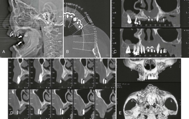
A, Scout view of the patient’s head; axial sections through the area of interest are indicated. B, Axial slice through the markers is used to display the orientation of the panoramic and cross-sectional images through the alveolar ridge. C, Panoramic views through the alveolar ridge demonstrate the relation of the markers to adjacent teeth. D, Cross-sectional slices through the area of the markers reveal the height and buccolingual dimension of the alveolar ridge, as well as the relation of the markers to the ridge. E, Three-dimensional reconstructions provide an overall impression of the bone contours and shape of the alveolar ridge.
Typical dental views reconstructed from a CT scan include axial (see Figure 73-3, B), panoramic (see Figure 73-3, C), and cross-sectional (see Figure 73-3, D) views of the jaws. Appropriate axial slices through the alveolar ridge of interest are selected as scout views. The curvature of the maxillary or mandibular ridge is then drawn on the axial slices, and panoramic images along the drawn line are created. Finally, cross-sectional slices, every 1 to 2 mm and perpendicular to the drawn curvature, are created. In addition to these flat, two-dimensional views, complex, three-dimensional images with surface rendering can also be generated from the CT data (see Figure 73-3, E). These images can provide useful information about the alveolar ridge defects that are easy to comprehend. Images can be printed on photographic paper or tr/>
Stay updated, free dental videos. Join our Telegram channel
VIDEdental - Online dental courses


