Chapter 3
PARTIAL PROSTHETICS
3.1 Introduction to partial prosthetics
Removable partial dentures are appliances that can be removed by the patient, and replace one or more missing teeth but not an entire arch.
A partial denture should:
- Restore appearance and masticatory function
- Be well retained and stable during function
- Be comfortable to wear
- Distribute occlusal forces favourably
- Prevent teeth drifting or over-erupting into edentulous spaces.
Partial dentures may be designed to utilise the remaining natural teeth in two ways. Firstly, the teeth can be used to aid the retention of the denture, keeping the denture in position. Secondly, the teeth may also be used to support the denture, distributing the occlusal forces applied to the denture through the hard tooth structure to the underlying bone.
The support for the partial denture may be considered and categorised as:
- Mucosa-borne (like a full denture), where support is gained from the underlying soft tissue (Figure 3.1.1).
- Tooth-borne, where the support is distributed through the remaining natural teeth (Figure 3.1.2).
- Tooth and mucosa-borne, where the support is provided by combination of the teeth and mucosa (Figure 3.1.3).
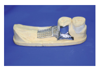
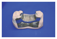
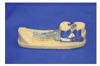
In this chapter we will discuss classification, component parts, designing dentures, denture support (mucosa-and tooth-borne dentures) and the production of mucosa-borne and tooth-borne dentures.
3.2 Classification
Kennedy classification
This classifies the pattern of tooth loss in the order of frequency with which they are met in clinical practice.
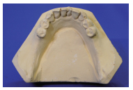
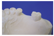
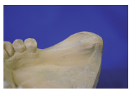
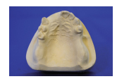
Class I: Loss of the distal teeth bilaterally; any denture provided will have two free-end saddles (Figure 3.2.1). (A saddle is the tooth-bearing part of the denture. A free-end saddle has a no natural tooth at one end (Figure 3.2.2), whereas a bounded saddle is an edentulous area with natural teeth mesially and distally (Figure 3.2.3).)
Modifications can be added to this class when further teeth are lost creating extra bounded saddles, e.g. Class I, modification 1, which has one extra bounded saddle (Figure 3.2.4).
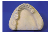
Class II: Loss of the distal teeth unilaterally, requiring a denture with a single free-end saddle (Figure 3.2.5).
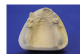
Modifications, involving extra bounded saddles, can be added as for Class I (Figure 3.2.6).
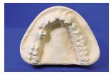
Class III: Loss of teeth producing a posterior bounded saddle (Figure 3.2.7).
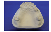
Modifications can be added as in Classes I and II (Figure 3.2.8).
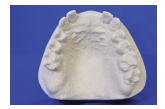
Class IV: Tooth loss producing an anterior bounded saddle (Figure 3.2.9).
No modifications are possible for this classification as the anterior saddle would become a modification of one of the other classes.
3.3 Component parts of partial dentures
Partial dentures have five distinct components: saddles, occlusal rests, clasps, reciprocation, connectors.
Saddles
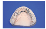
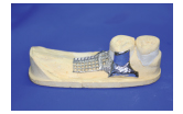
The saddle is the part of the denture that carries the artificial teeth over the edentulous area or saddle area. Saddles may be designed as mucosa-borne to transmit the occlusal load through the mucosa (Figure 3.3.1) or tooth-borne, where occlusal rests transmit the load to the adjacent teeth (Figure 3.3.2).
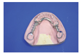
Saddles may be tooth- and mucosa-borne where the occlusal load is transmitted to both natural tooth and mucosa (Figure 3.3.3).
To minimise the load through the mucosa the extension of the saddle is designed to cover the maximum surface area possible, thus increasing the footprint of the saddle and spreading the load more widely. The occlusal table, (the surface area of the occlusal surface of the denture) may also be kept to a minimum by decreasing the bucco-lingual width of the denture teeth or by using less teeth.
Occlusal rests
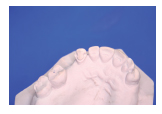
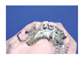
Occlusal, incisal or cingulum rests are used to provide support for tooth-borne dentures by transmitting the occlusal load to the teeth (tooth-supported denture). They are small metal components that are an integral part of the denture base. This type of support prevents sinking of the denture (movement towards the mucosa) into the soft tissues by transferring occlusal loads to the remaining natural teeth. the natural teeth are prepared to have seats for the occlusal rests to prevent occlusal interference with the opposing teeth and to ensure force is directed down the long axis of the tooth (Figures 3.3.4 and 3.3.5).
Rest seats should be saucer-shaped to allow good oral hygiene. If no occlusal interferences are likely then rest seats need not be prepared.
Incisal and cingulum rests serve the same function on anterior teeth. Again seats are prepared to prevent occlusal interference and avoid the unsightly appearance of metal at the front of the mouth. Rests on the lingual surface of canine teeth almost always require some preparation of the tooth, either to emphasise the cingulum or prevent interference with the opposing teeth.
Clasps(direct retainers)
Clasps provide retention (direct retention) for the denture. When fully seated, partial dentures are passive in the mouth. It is only when forces (sticky food) attempt to dislodge them that retentive elements become active. The flexible tip of a clasp arm contacts the tooth in an undercut area, remaining passive when seated, but exerting force when the denture is being removed.
There are two main types of clasp:
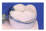
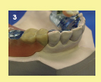
Occlusally approaching (suprabulge): Approaches the undercut from the occlusal surface of the tooth. The entire arm contacts the tooth, but only the flexible tip enters the undercut to serve as the retainer (Figure 3.3.6).
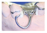
Gingivally approaching (infrabulge): Approaches the undercut from the gingival area and should only contact the tooth with the clasp tip (Figure 3.3.7).
Each type has several different designs and are discussed later in the chapter.
Reciprocation
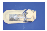
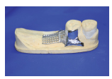
When a clasp applies force to a tooth, some of that force acts laterally. This unfavourable force may lead to tooth movements or simply render the clasp inefficient. Therefore reciprocation to this force is provided. This is a component that acts to maintain the tooth in position as the clasp exerts force. It lies on the opposite side of the tooth to the clasp tip and is either a reciprocating arm (Figure 3.3.8) or plate (Figure 3.3.9).
Connectors
Connectors link the saddles and other component parts. They should be rigid, shaped such that they are comfortable for the patient, and hygienic, keeping distant from the gingival margin where possible.
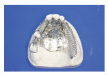
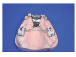
Major connectors link saddle areas, and the most common are palatal plates (Figure 3.3.10) or bars (Figure 3.3.11).
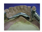
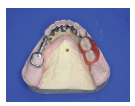
For mandibular dentures lingual bars (Figure 3.3.12) and plates are the most common (Figure 3.3.13).
Minor connectors attach small components such as occlusal rests and clasps to the denture. They should be designed to be hygienic and have the minimum bulk necessary while retaining adequate strength.


Denture base material
Partial denture bases are made of acrylic or cast cobalt-chromium. Acrylic is chosen for most mucosa-borne dentures and all temporary dentures (Figure 3.3.14). Cobalt-chromium alloy is used for tooth-supported designs, and occasionally for mucosa-borne dentures when indicated on account of its strength (Figure 3.3.15).
3.4 Surveying
Primary Models
Survey
Design
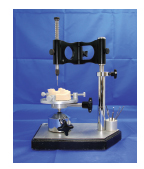
A surveyor is an instrument that is used to keep a tool in a parallel plane relative to a study model (Figure 3.4.1).

There are several tools that may be used in the surveyor arm (Figure 3.4.2):
- Graphite marker
- Analysing rod
- Chisel
- Measuring gauges.
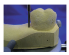
Surveying identifies areas of undercut formed by the shape of the teeth that may be used to provide mechanical retention. Surveying also identifies those areas that must be eliminated to allow insertion and removal of the denture (Figure 3.4.3).
Undercut may be used to create mechanical retention in two ways: firstly, by creating a path of insertion that is different to the path of displacement; and secondly, by engaging undercut with clasp arms (see Section 3.5).
Creating a path of insertion


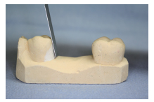
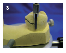
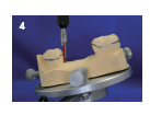
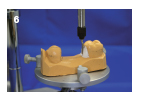
Consider the bounded saddle in Figure 3.4.4. Undercuts are easily identified to the mesial of the molar and the distal of the premolar (Figures 3.4.5 and 3.4.6).
This is undercut relative to the path of displacement. The path of displacement is the pathway that the saddle will take when being dislodged by sticky food. We can assume that it is at right angles to the occlusal plane. There are four possible ways to produce a saddle in this situation:

1. Fill both undercut areas with the denture saddle (Figure 3.4.7)
The undercut areas relative to the path of displacement are both filled. This results in the saddle having excellent retention relative to the path of displacement, unfortunately the denture cannot be withdrawn or inserted, making this unworkable.

2. Do no fill either of the undercuts with the denture saddle (Figure 3.4.8)
The undercut areas have been identified and ‘blocked-out’ with plaster on the working model. The denture has been produced on the blocked out model; here the undercut is not used and therefore no retention is gained. The path of insertion = path of displacement.
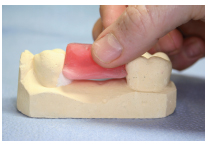
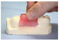
3. Fill the undercut mesial to the molar with the denture saddle (Figures 3.4.9 and 3.4.10))
The undercuts relative to the path of insertion are identified, and one is filled with the saddle to aid retention. To ensure that the denture may be removed, the undercut is blocked out distal to the premolar. Note that the plaster is angled to match the mesial surface of the molar, creating a path of insertion. The path of insertion is different from the path of displacement, creating retention.
4. Fill the undercut distal to the premolar with the denture saddle (Figure 3.4.11)
5. Utilise the undercut distal to the premolar for retention
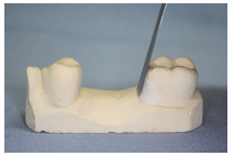
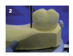
The final option is to utilise the undercut distal to the premolar for retention. The undercut mesial to the molar is eliminated and shaped to match that of the distal surface of the premolar. The path of insertion is different from the path of displacement creating retention (Figure 3.4.12).
To aid the identification of these small undercut areas, a surveyor is used to hold the model on a horizontal platform. The vertical column allows tools to be moved around the teeth while maintaining the same plane.
Surveying to create a path of insertion
Previously the surveying principle has been considered in relation to a single saddle. In practice, a patient may have two or three saddle areas with teeth adjacent to each. Here, the most favourable path of insertion should be sought.
Displacement of a denture is oft en caused by the adhesion of food to the occlusal surfaces. This results in the displacement of the dentures at right angles to the occlusal plane. Therefore creating a path of insertion that differs from the path of displacement improves retention.
Clasps should also be taken into consideration at this stage. See Section 3.5




Stay updated, free dental videos. Join our Telegram channel

VIDEdental - Online dental courses


