Chapter 25
PLANNING FOR THE FUTURE
The cases under consideration in this text are those in which restorative treatment has failed. It is, therefore, prudent to look ahead and consider modifications which may be required in the future. The following are some examples of planning for the future.
General Considerations
Sportsguards
On completion of anterior ceramic crowns or bridgework, it is sensible to fabricate a sportsguard immediately. This is done primarily in case the patient requires a general anaesthetic, when the sports guard can be inserted by the anaesthetist prior to intubation to protect the crowns. A sportsguard is also useful in the event of the patient playing contact sports.
Retained Roots
Caries and periodontitis free roots can be retained so they:
- Provide support for a denture (Fig 25-1).
- Maintain alveolar bone.
- Allow for future restorations, should adjacent teeth fail.
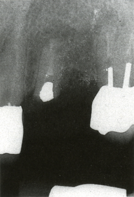
Fig. 25-1a Retained root for future use and support of a denture. The patient did not want implants. The bridge from 22 to 24 had failed.
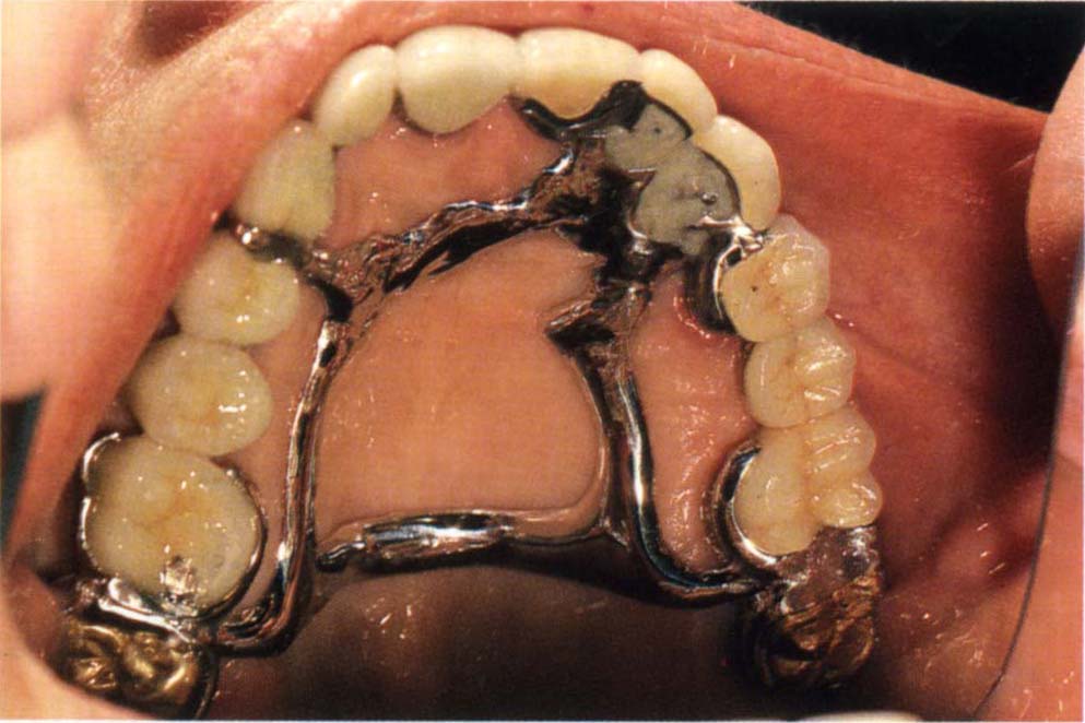
Fig. 25-1b Denture framework.
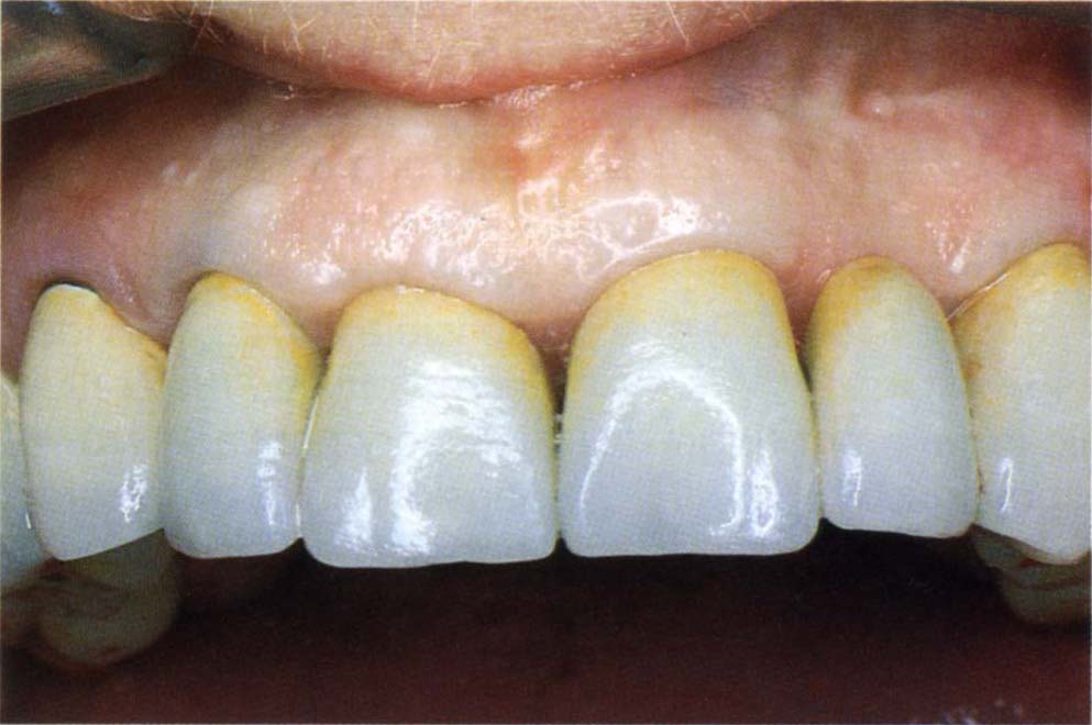
Fig.25-1c Denture replacing 22 and 23. The root of 22 retains the bone.
‘Sleeping’ Implants
Osseointegrated fixtures can be placed – for example, at the time of periodontal surgery – and only exposed later, should the need arise. This can save three to six months of treatment at a later stage (Fig 25-2).
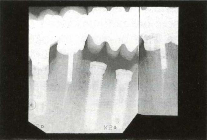
Fig. 25-2 “Sleeping” implant for future use, if required.
Restorative Considerations
Some examples of features which may usefully be built into restorations, with possible future modifications in mind, will be described. This list does not pretend to be exhaustive.
Canine Guidance to Group Function
Since the canine is an easily accessible tooth near the front of the mouth and has a long clinical crown, it is very suitable for obtaining unimpeded guidance when restoring a dentition. Although there is no convincing clinical research to favour this form of anterior guidance over another, clinical considerations make it a sensible choice, provided that the tooth is firm and not compromised restoratively by, for example, an unsatisfactory post and crown. It is easier to see the markings of occlusal indicator tape at the front of the mouth and easier to provide unimpeded movement on a single tooth than on several teeth (that is, group function). However, in anticipation of possible wear or movement at a later date, it is sensible to provide group function at a shallower anterior guidance than that provided by the canine.1 To do this, after canine guidance has been fabricated, the canine is removed from the cast and the posterior segment fabricated to group function (Figs 25-3a–b) at a flatter anterior guidance (Appendix). It is important to ensure that non-working contacts are not introduced on the cast. Should the canine wear or move, the occlusion will change to a planned group functional guidance, rather than a random guidance avoiding, for example, excessive loading on unsupported porcelain or an already compromised abutment.
Fig. 25-3 Canine guidance with facility to ‘drop into’ group function if canine should move or wear. Ensure that removal of the canine does not introduce non-working side contacts.
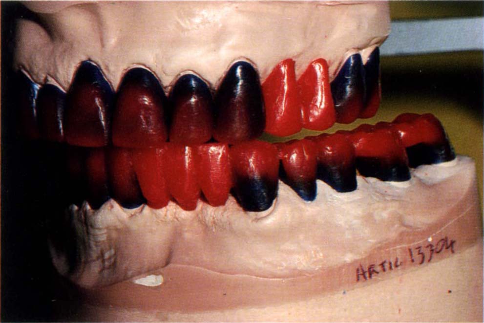
Fig. 25-3a Waxed to canine guidance.
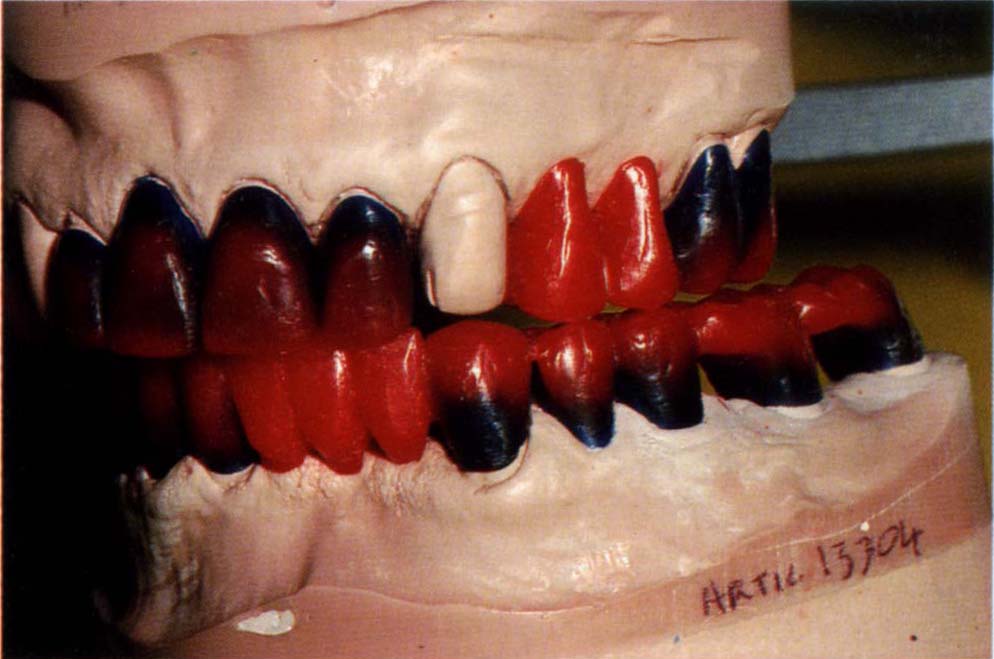
Fig. 25-3b Canine removed and posteriors waxed to group function. Ensure that this does not introduce non-working side contacts.
Occlusal Stabilization Appliance
Following the provision of extensive ceramo-metal or ceramic restorations for a patient with powerful masticatory musculature and a history of bruxism, it is sensible to make an occlusal stabilization appliance. This is worn during periods of stress to reduce the risk of porcelain fracture. Similarly, in the presence of crowns with short posts or grossly different mobility between abutments, it is sensible to distribute forces as widely as possible. A stabilization appliance may help.
In the presence of a large horizontal : vertical ratio between CRCP and the IP, deflective contacts should be incorporated on the appliance to prevent distal repositioning of the mandible (Chapter 4).
The patient should be provided with both the sportsguard and the stabilization appliance before the need for them actually arises, so that they are immediately available.
Copings
In terms of planning for the future, copings have two advantages, namely:
- They allow future modification.
- They ‘permit’ cementation failure.
The main disadvantages of copings relate to the creation of a bulbous ceramo-metal superstructure, giving rise to:
- Aesthetic problems.
- Gingival problems.
The disadvantages regarding copings must be the weighed against the advantages. The patient’s aesthetic perception is obviously relevant in this context.
Future Modification
If it is thought that the bridge segment will later have to be removed and modified, due, for example, to the need for removal of a root or a tooth or to gain access to an osseointegrated fixture (Chapter 33), copings on the abutment teeth in conjunction with cementation with temporary cement will permit this.
It is important to remember that, as stated previously in Chapter 18, it is often difficult to remove such bridgework and periodic removal is contraindicated if ceramo-metal retainers have been used. Usually such bridgework should be cemented with a mix of Tempbond and Vaseline (1 length base : 1 length catalyst; half a length Vaseline from a 2 ml syringe). If the bridgework becomes uncemented, the Vaseline is reduced until retention is adequate.
Cementation Failure
Cementation failure can be expected in:
(i) Long spans and short clinical crowns.
Sometimes it is not feasible to increase the clinical crown height by surgery, as the latter would lead either to exposure of the furcation, or, in the presence of a high external oblique ridge, to movement of the gingival tissue into the cheek, rather than into the sulcus. Also, the medical condition of the patient may contraindicate such an approach or the patient may refuse surgery. In such cases, it is preferable to cement the bridge with temporary cement over copings, so that any cementation failure is between superstructure and coping, rather than between bridge and tooth (Fig 25-4).
(ii) Long span cantilevers with non-mobile abutments (see Chapter 19). In such cases cementation failure or mechanical failure of the restorations is likely. Cementation of the superstructure with temporary cement is usually followed within three years by cementation failure between the superstucture and copings at one or two points, but without failure of the overall retention. This presumably results in relief of stress on the definitive cement between coping and abutment and on the porcelain. It is interesting that no halitosis develops.
(iii) Cases with different mobility between bridge abutments, particularly if a pier abutment is more mobile than end abutments. Hydrostatic pressure during cementation will force the more mobile unit out of the casting (Chapter 18). The presence of an individually cemented coping on this abutment results in an open margin between the coping and superstructure, rather than between retainer and tooth.2
(iv) Provisional bridgework. If there is a high caries susceptibility, it is prudent to make the provisional bridge over copings, so that cementation failure will occur between the coping and superstructure, rather than between the superstructure and the underlying tooth (Chapter 8). If the bridge becomes uncemented on one abutment, it will be retained by the other retainers but caries will not occur in the uncemented abutment.
Fig. 25-4 Telescopic bridge – in presence of the risk of cementation failure.
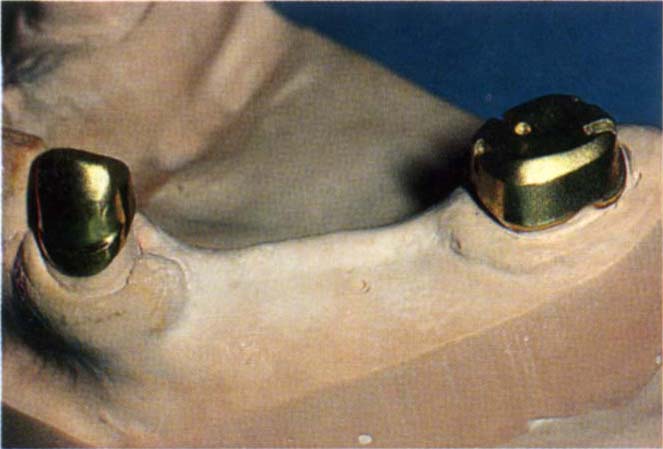
Fig. 25-4a Long span bridge with short clinical crowns. Clinical crown lengthening surgery is not possible because of high external oblique ridge.
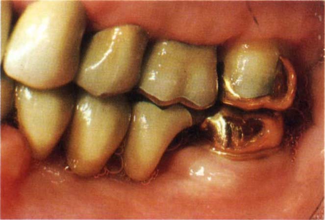
Fig. 25-4b Telescopic bridge cemented with Tempbond over copings cemented with zinc phosphate cement. Cementation failure is most likely to occur between the superstructure and the underlying coping rather than the coping and tooth.
Intracoronal Attachments
Planning for Tooth Loss and Bridge Refabrication Using Mesial and Distal Abutments
If it is considered likely that a tooth will be lost, then an intracoronal attachment (laboratory fabricated or prefabricated, for example, Stern Mini, or Cendres et Metaux 21:03:02) should be incorporated into the distal surface of the tooth anterior to the suspect tooth (Fig 21 -2b). An impression and cast should be made of the restorations for future reference. If the tooth is lost, by using indices from the cast, fabricating a conformative fixed-movable bridge built into the attachment is straightforward (Appendix).
Planning for Tooth Loss and Replacement with a Partial Denture (Particularly for Anticipated Loss of a Distal Section)
If it is considered that the distal section of bridgework may require replacement with a partial denture, then four features are incorporated into a pontic anterior to the questionable abutments, namely:
- Intracoronal attachment.
- Lingual arm.
- Guide plane.
- Buccal undercut.
Figures 25-5a–b shows these components (Appendix).
Fig. 25-5 Planning for the future loss of posterior units.
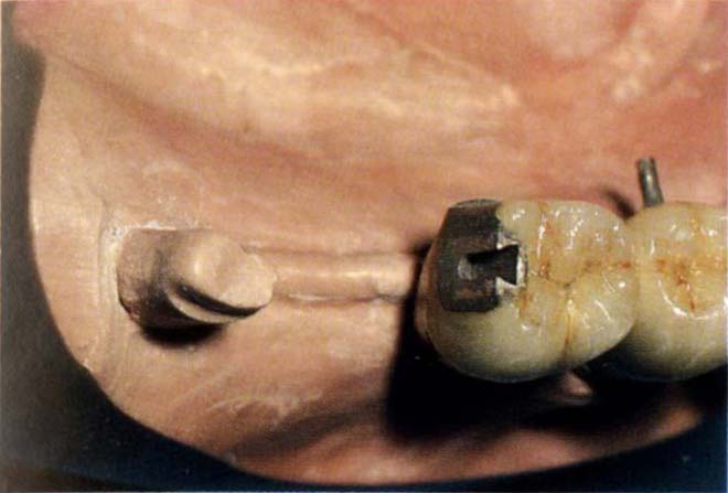
Fig. 25-5a Planning for replacement with a denture or new posterior bridge – intracoronal attachment within pontic, lingual milled surface to receive an arm, guideplanes, distobuccal undercut.
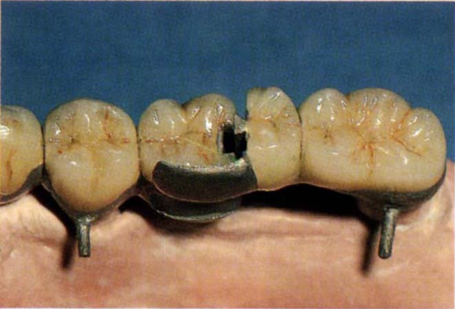
Fig. 25-5b Posterior section seating to place.
Intracoronal Attachment
With a future partial denture in mind, it is preferable to use a prefabricated attachment, for example, the Beyeler attachment (Cendres et Metaux 21:03:2) as this provides very positive guide planes.
Lingual Arm
A lingual recess is milled into the pontic so that a lingual arm can be incorporated on the more distal retainer (Fig 25-5). This provides lateral stability to the joint and prevents premature wear of the intracoronal attachment, which is particularly relevant when the abutments have diminished periodontal support and are mobile. Additional stability can be gained by incorporating a lingual screw. When the retainers are tried in the mouth, it is preferable that the casting incorporating the intracoronal attachment patrix and lingual arm is separate from the retainers. A pickup of this device is made from the mouth and then soldered to the retainer. The solder joint is shown in (Fig 25-5c).
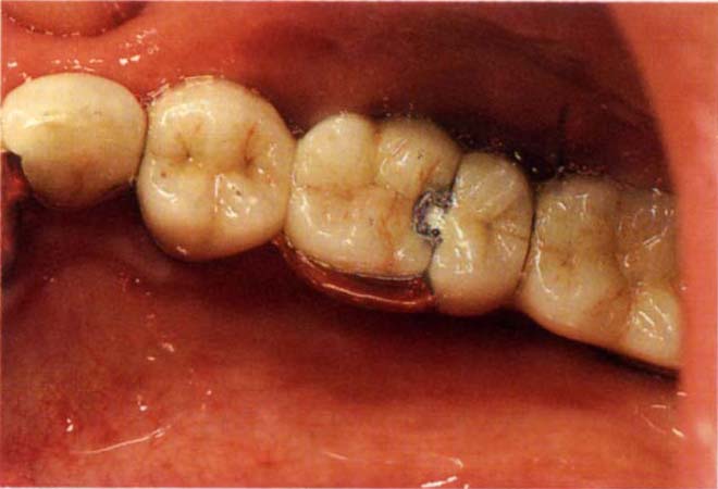
Fig. 25-5c Solder joint on mesial aspect of the lingual arm. Antiflux was placed on the remainder of the arm. If failure occurs the solder is cut, the posterior section removed and a replacement made.
Guide Planes
Guide planes are incorporated (Fig 25-5b) on the distal and lingual surfaces, increasing the frictional resistance between the components and providing guideplanes for a future denture.
Buccal Undercut
A mesiobuccal or distobuccal undercut is provided on the pontic to allow future engagement by a clasp.
If the bridgework is removed and replaced by a partial denture, all of the above features are available for denture resistance and retention. Clasp arm retention with a simple intracoronal attachment is preferable to adjustable intracoronal retainers, as the former allows greater flexibility for future adjustment.
Since the retainer will be rigid, it is important to use an altered cast technique for denture fabrication. The intracoronal patrix is not attached until the denture base is stable (see Chapter 32 and the Appendix). The pontic containing the attachment mut be supported, anteriorly, by a suitable number of retainers with adequate resistance and retention.
Bi-Directional Attachments
Sometimes it is uncertain which of two teeth has the poorer prognosis and, in consequence, the wrong choice could be made about which should incorporate the matrix of an attachment. Extension of the base of the matrix into another opening (Fig 25-6a) makes it possible to remove either the crown containing the patrix or the crown containing the matrix (Fig 25-6b). See the Appendix for laboratory procedures.
Fig. 25-6 Bi-directional attachments.
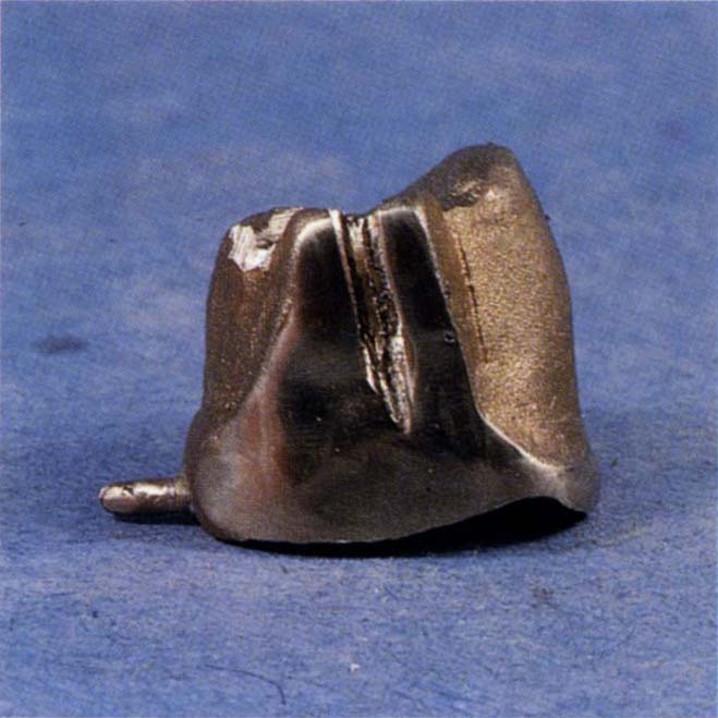
Fig. 25-6a Crown with matrix so that the patrix can be removed through the open base of the slot.
Stay updated, free dental videos. Join our Telegram channel
VIDEdental - Online dental courses


