CHAPTER 2
A New Biologic Classification of Bone Augmentation
There is a miracle when two things unite to form something new.
—Samuel Butler
Augmentation of alveolar bone loss should constitute regeneration of the tissue being replaced and not simply spatial repair.1 Osseous and soft tissue surgery should therefore reconstruct both form and function of the desired replacement tissue.
 Rationale for the New Classification
Reconstructive bone graft repair of osseous defects does not always form well-vascularized bone, even when the defect is filled.2 True regeneration implies that the defect is filled with viable mineralized tissue that models and remodels as bone and is not an admixture of devitalized inclusions or scar tissue. Bone generation methods for defect reconstruction can be differentiated according to bone graft vitality, the extent of consolidation, and marginal integration. These aspects can only be verified by late-term biopsy findings to determine the extent of vital mineralization.3 However, routine biopsy analysis is impractical.
Short of invasive procedures to verify graft performance, hard tissue augmentation can be empirically classified based on vascularization of the grafting approach used, in order to suggest the likely vitality of the graft. Therefore, we propose that our earlier classification4 for bone generation techniques in defect reconstruction be differentiated into five classes, according to vascularization or induction of vascularization:
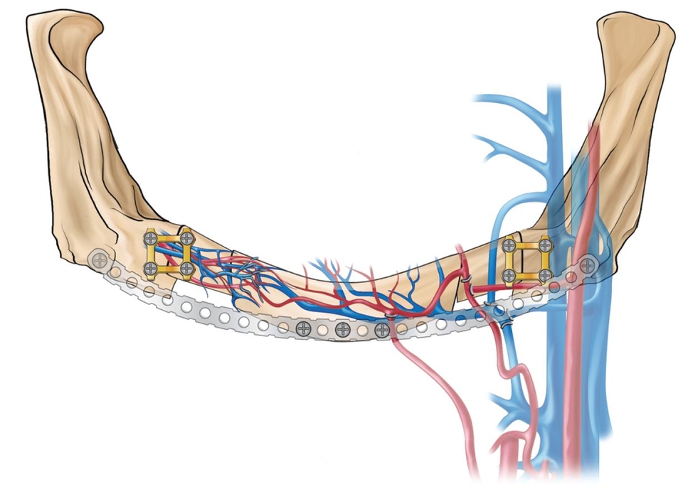
- Class I: Microanastomosed free bone flaps (Fig 2-1a)
- Class II: Distraction osteogenesis (Fig 2-1b)
- Class III: Pedicled segmental osteotomies (Fig 2-1c)
- Class IV: Bone morphogenetic induction grafts (Fig 2-1d)
- Class V: Nonvascularized bone grafts (Figs 2-1e and 2-1f)
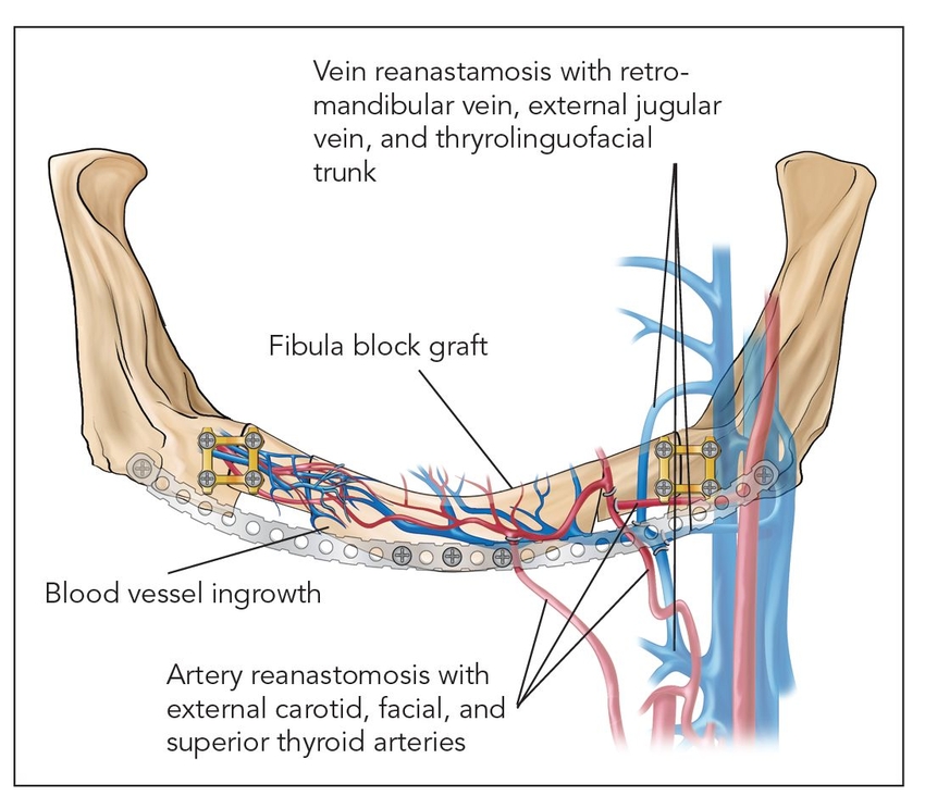
Fig 2-1a Class I: Microanastomosed free bone flap.
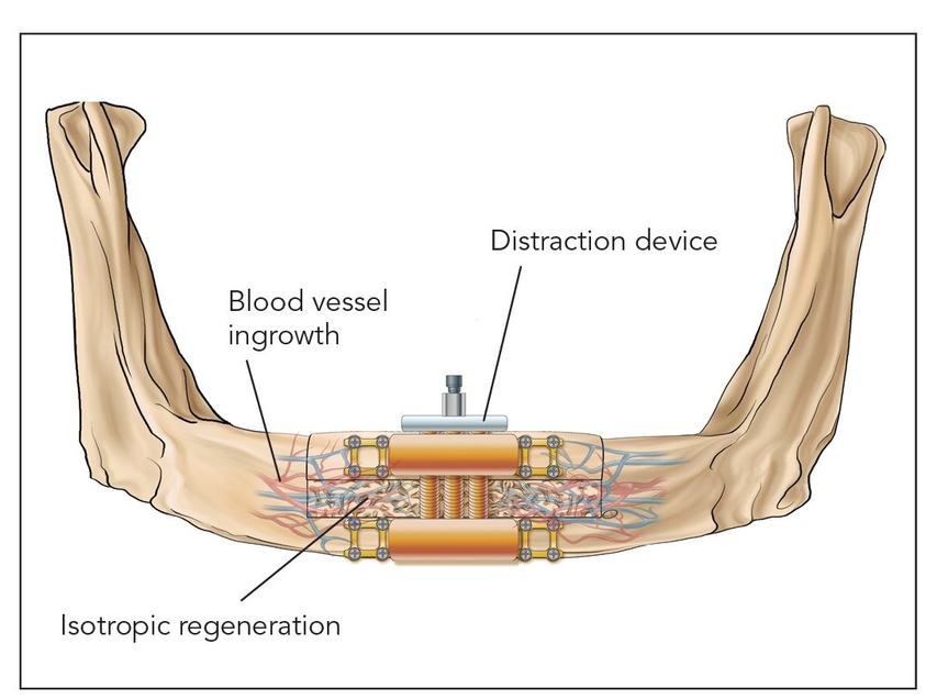
Fig 2-1b Class II: Distraction osteogenesis.
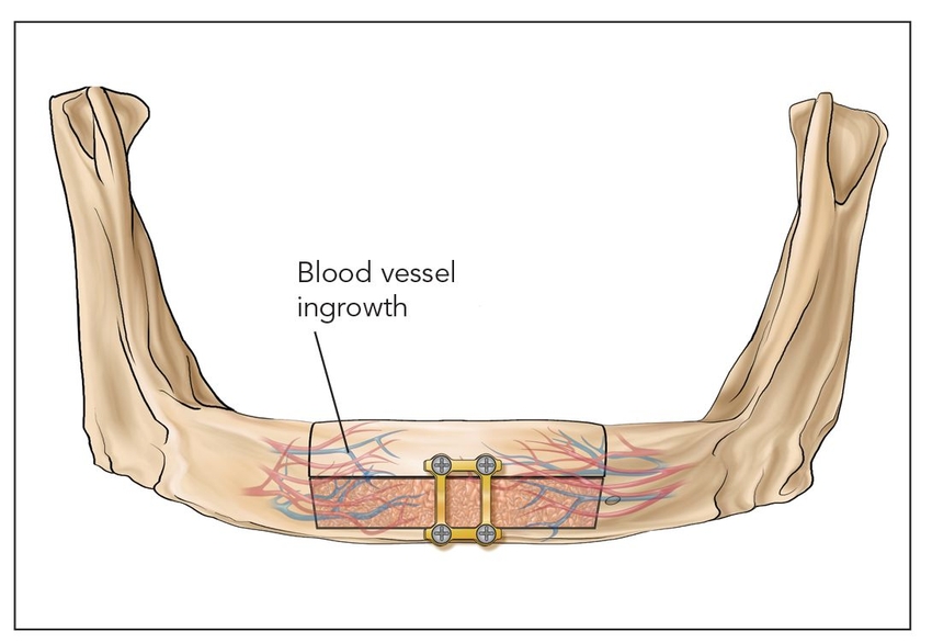
Fig 2-1c Class III: Pedicled segmental osteotomy.
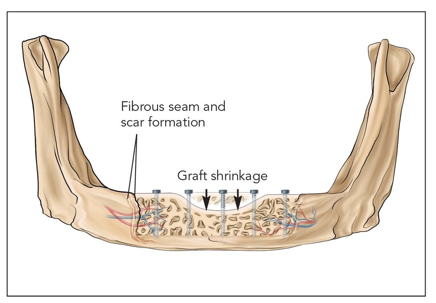
Fig 2-1e Class Va: Onlay block graft.
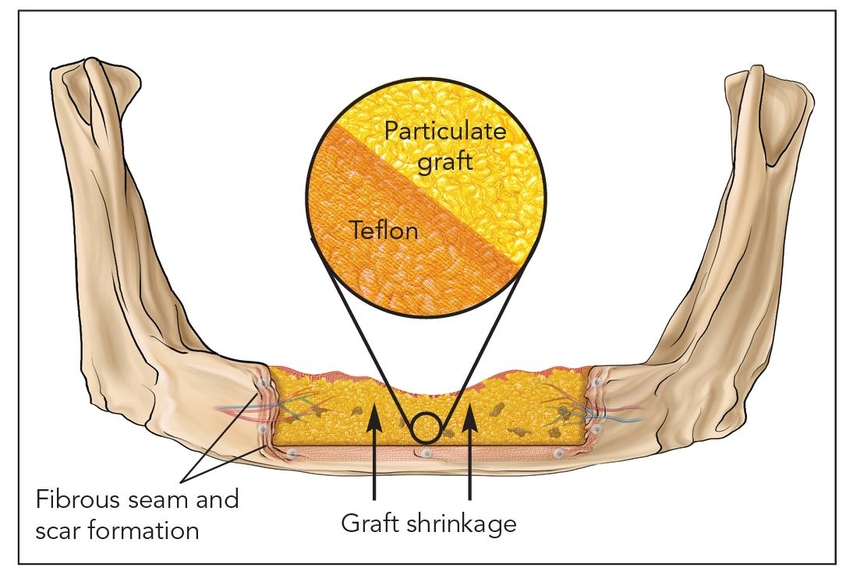
Fig 2-1f Class Vb: Guided bone regeneration.
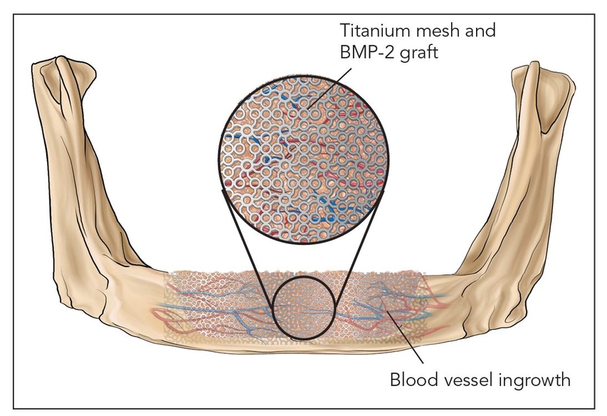
Fig 2-1d Class IV: Bone morphogenetic induction graft. BMP-2—bone morphogenetic protein 2.
 Biologic Responses to Bone Augmentation Techniques
Class I: Microanastomosed free bone flaps
Bone transplanted in conjunction with attached vessels, both artery and vein, as a composite pedicled graft is completely revitalized by micro-reanastomosis.4 When this is done, as in free fibular grafts, osseous volumetric stability persists because there is a continuous blood supply to the graft.5 The new bone is more like native bone in terms of quality, functionality, consolidation, and seamless integration than is bone generated by any other augmentation technique. Therefore, the bone generated is highly stable and does not resorb secondary to ischemia. This applies to highly compromised sites such as that shown in Fig 2-2 of a patient who presented with a large mandibular fibrous dysplasia lesion. This lesion was treated with a vascularized fibula graft immediately following resection, and implant reconstruction followed healing of the graft.
Class II: Distraction osteogenesis
Osteotomized bone that is slowly spread apart in a process termed callus distraction leads to osteogenesis, a highly vascularized epigenetic response induced by a morphogenetic protein cascade; the end result is a much more vital bone than is found in typical bone grafts.6,7 Distraction osteogenesis forms well-vascularized isotropic bone that takes on the same conformation as the distraction callus.8 There is little resorption within the distraction zone as long as there is an adequate healing time and torsion and compression are avoided until laminar bone is formed and remodeled, in about 4 to 6 months9 (Fig 2-3).
Class V: Nonvascularized bone grafts
Class Va: Onlay block graft
Nonvascularized autogenous block bone grafts are stabilized on the host bed with rigid fixation.17 These types of grafts must be revascularized and undergo significant remodeling by creeping substitution.17 These types of grafts do not become fully consolidated and often remain as a mixture of devitalized bone.18 Onlay block grafts are at great risk for long-term resorption, with a possible volume loss of 50% or greater.19,20 Different block bone grafts perform differently, and iliac corticocancellous, calvarial, and mandibular block grafts have varied responses.21–23
Fig 2-2 Microanastomosed free bone flaps
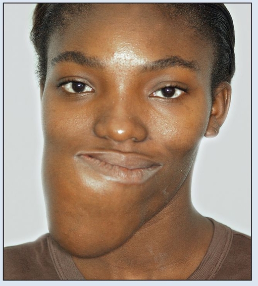
Fig 2-2a Preoperative frontal facial view.
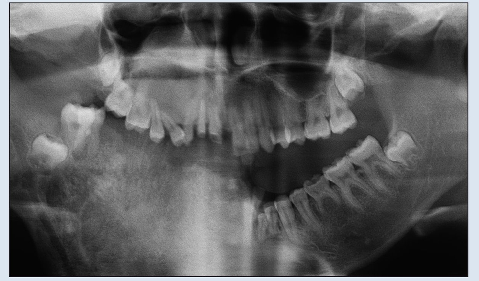
Fig 2-2b Preoperative panoramic radiograph demonstrating extent of destruction. Confines of the lesion extend beyond the film borders.
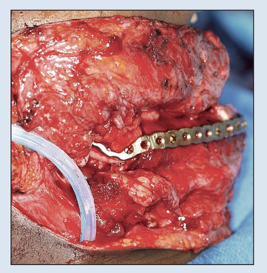
Fig 2-2c Immediate osseous reconstruction is achieved with a microvascular free tissue transfer (MFTT) of a fibula flap secured to the plate. (MFTT by Dr D. D. Kim, Shreveport, LA.)
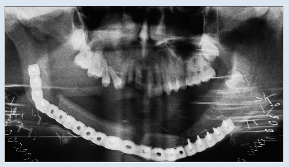
Fig 2-2d Immediate postoperative panoramic radiograph. Note the removal of both coronoid processes to facilitate rehabilitation.
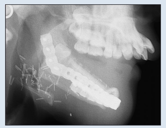
Fig 2-2e Immediate postoperative lateral cephalogram demonstrating adequate relationship with maxilla for dental rehabilitation.
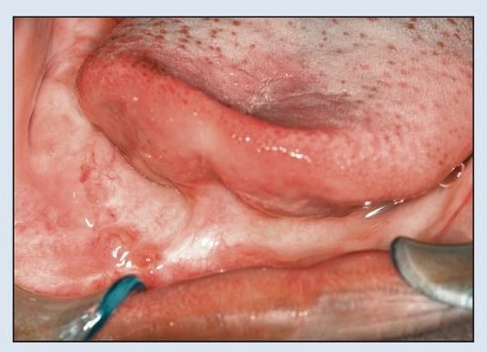
Fig 2-2f Postoperative view 1 year following resection.
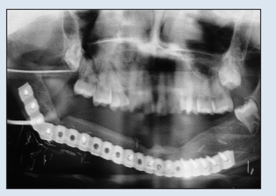
Fig 2-2g Postoperative panoramic radiograph demonstrating osseous healing at the osteotomy and fixation sites at 1-year follow-up.
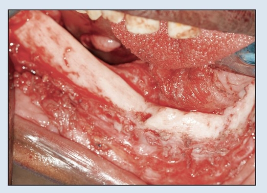
Fig 2-2h Intraoperative view following trans-oral plate removal demonstrates appearance of “neo-mandible.”
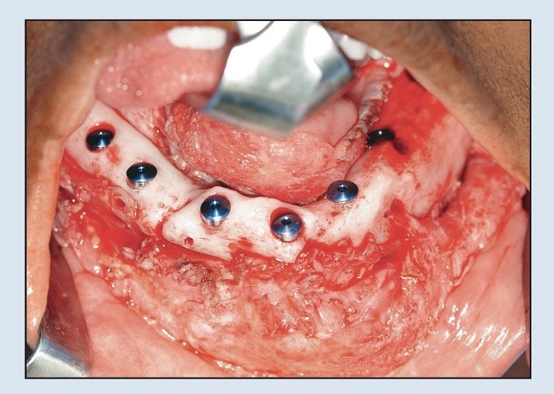
Fig 2-2i Immediate placement of six dental implants following plate removal.
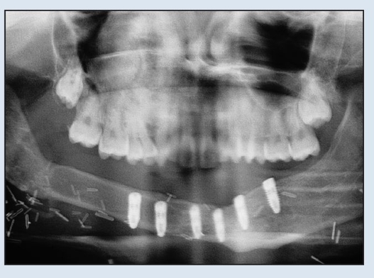
Fig 2-2j Postoperative panoramic radiograph shows absence of plate and placement of implants.
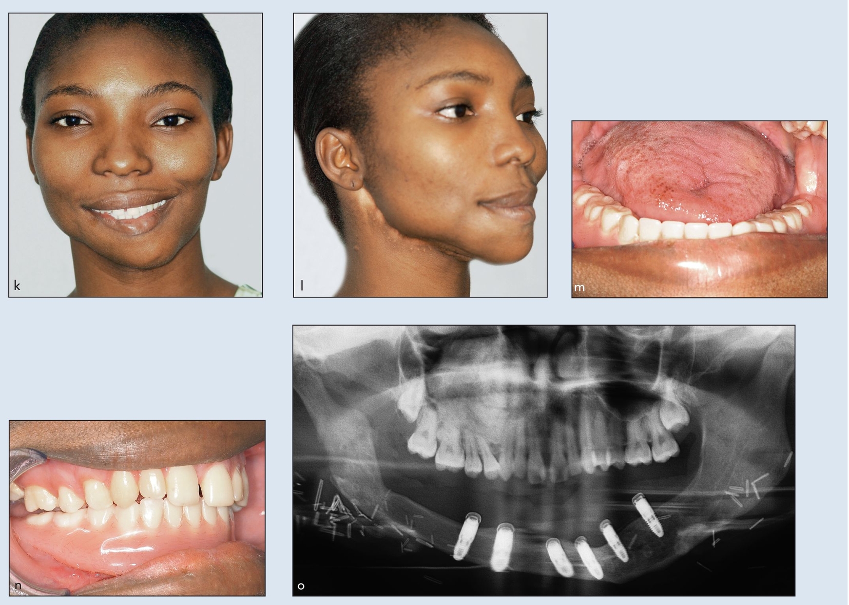
Figs 2-2k to 2-2o Definitive frontal (k) and three-quarter (l) facial views 2 years after initial resection and MFTT reconstruction. Definitive prosthesis from open-mouth (m) and closed-mouth (n) views. (o) Definitive panoramic radiograph demonstrating implant attachments. (Prosthesis by Dr W. P. Cunningham, Shreveport, LA.)
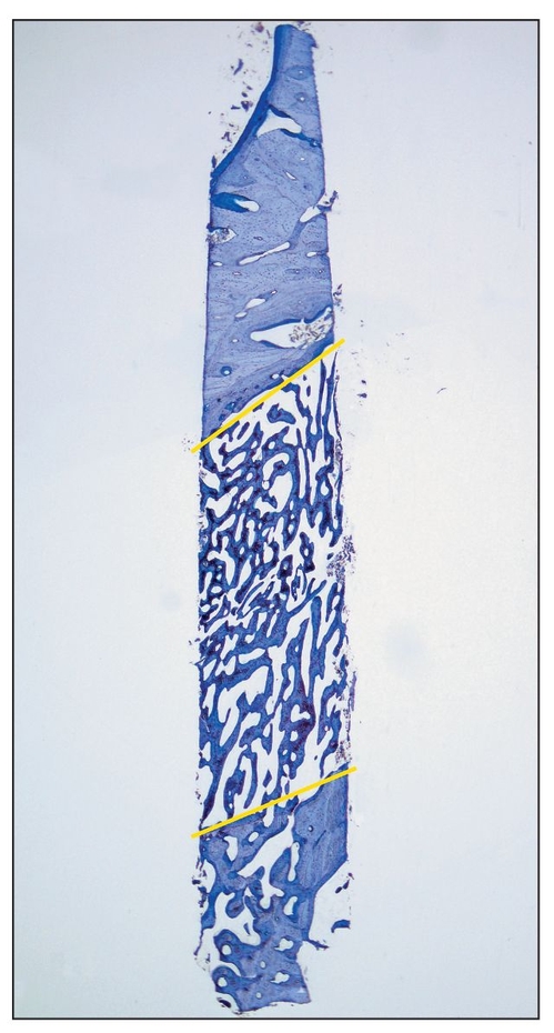
Fig 2-3 Histologic view of a core specimen taken from the region of a mandibular right second premolar 3 weeks after the completion of a 3-month healing period for a distraction procedure. (top) Apical region; (bottom) caudal region; (yellow lines) former osteotomy lines (toludine blue; original magnification).
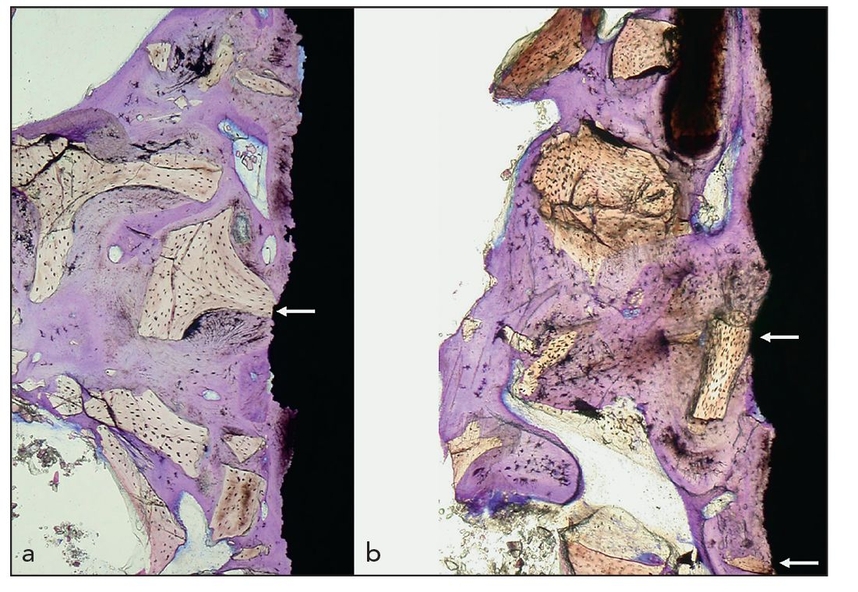
Figs 2-4a and 2-4b Histologic specimens of a dental implant removed after almost 19 years of loading in a 63-year-old woman. The original procedure involved a maxillary sinus floor elevation and grafting with Bio-Oss (Geistlich) and immediate application of the dental implant. The implant was removed because of peri-implant infection and maxillary sinusitis. (white arrows) Direct contact of the implant surface with the foreign-body material (toludine blue; original magnification ×15).
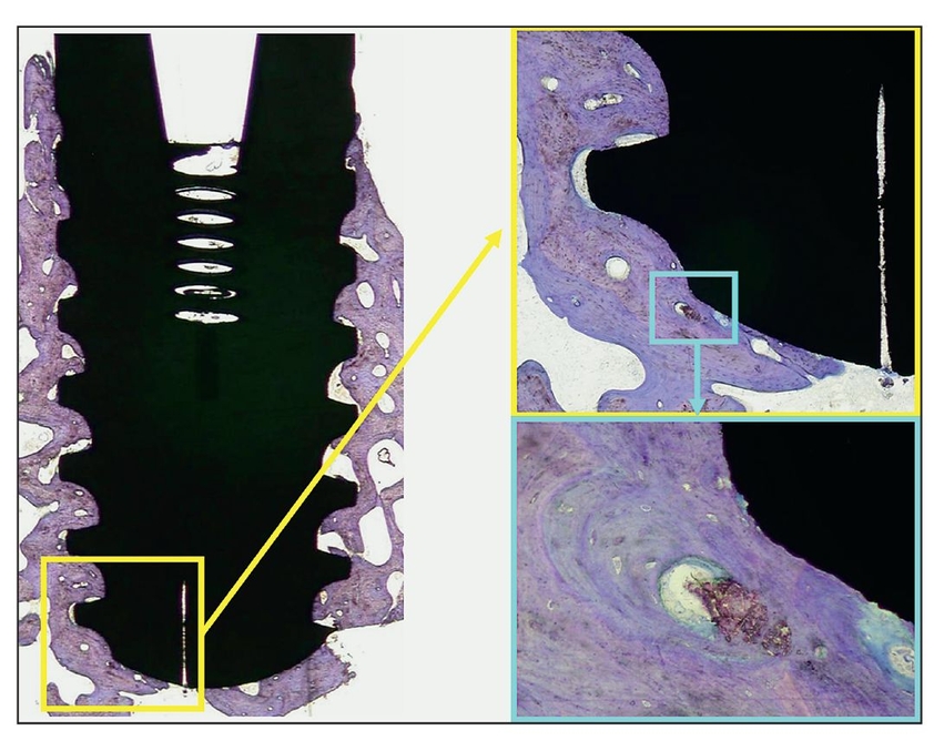
Fig 2-5 Histologic view of peri-implant osseointegration 5 years after treatment and 3 years after implant placement. A defect was filled with Algisorb following removal of an odontogenic keratocyst, and an implant was placed. The implant was removed because it was located very close to a recurrence of the tumor (toludine blue; original magnification ×2). (yellow box) Apical detail of the implant on the right side (original magnification ×20); (blue box) increased magnification of the detail (original magnification ×40).
Osteoconduction
Resorption replacement of bone-forming material is essential for osteogenesis as well as for the integrity of osseointegration. 28 When osteoconductive graft material does not resorb, it essentially remains a foreign body; when the graft is in direct contact with an implant surface, osseointegration may be compromised because it is less resistant to infection29 (Fig 2-4). Therefore, augmentation materials must be distinguished with respect to their ability to undergo replacement resorption by differentiating materials into two categories: bone-forming materials and bone-replacement materials.
Bone-forming materials are resorbed by creeping substitution and replaced during remodeling. Bone-replacement materials, in contrast, essentially take the place, and in a sense displace, bone mineral and are not resorbed. For example, Algisorb (Osseous Technologies; formerly C Graft or Algipore) is an osteoconductive bone-forming material because very little alloplast persists after a few years; the associated dental implants are completely surrounded by bone30 (Fig 2-5). Bone-replacement materials include nonresorbing or very slowly resorbing hydroxyapatite products such as anorganic xenograft.31
 Surgical Procedures and Their Applications
The surgical procedures that fall within each classification category are listed in Box 2-1.
Re-anastomosed fibula bone grafts
The ideal graft is a vascularized hard and soft tissue structure that is transferred to a deficit site with vascular re-anastomosis. Even in complex oral and maxillofacial surgical defects (Fig 2-6a), osseous union and a stable reconstruction can be obtained following a well mortised fixed graft reconstruction (Figs 2-6b to 2-6e). Sources for vascularized bone flaps include the iliac crest, scapula, radius, and fibula, with the fibula being the site the most frequently employed (Figs 2-6f to 2-6i). Maxillary reconstruction of a large oral antral communication is completed with implant placement followed by prosthetic management (Figs 2-6j and 2-6k). Treatment of this type of defect cannot be done without the optimal bone healing provided by a vascularized bone graft.
Fig 2-6 Re-anastomosed fibula bone graft
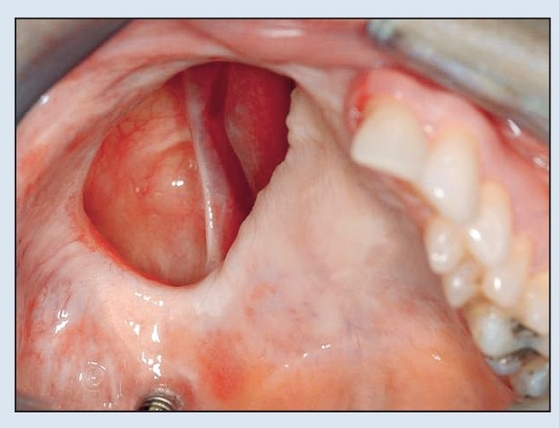
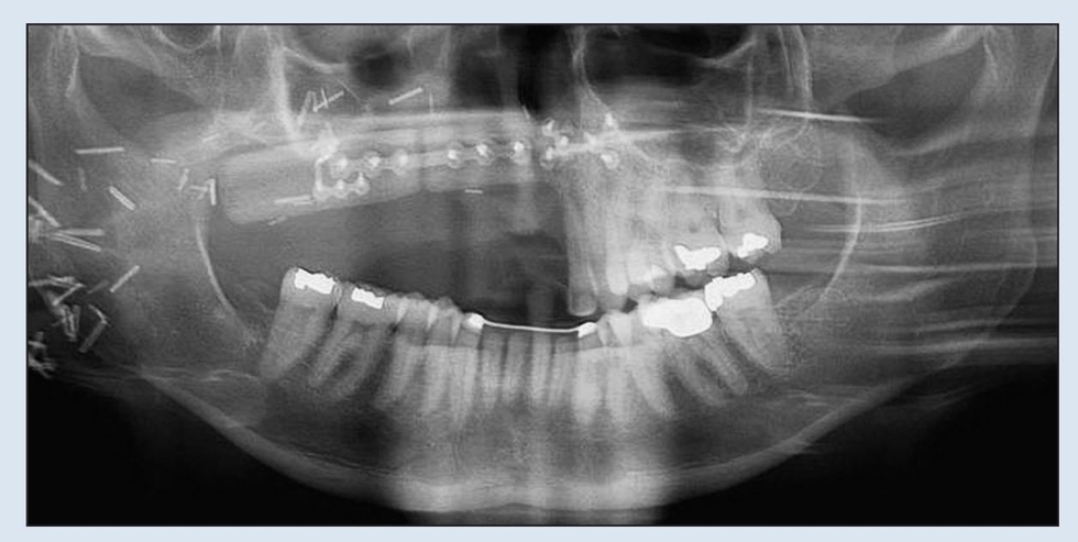
Fig 2-6a Preoperative intraoral view demonstrating oro-antral communication and solitary implant.
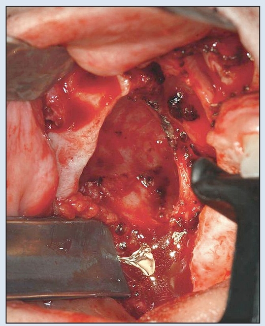
Fig 2-6b Preparation of the maxillary defect to produce adequate exposure of the bony buttresses.
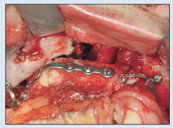
Fig 2-6c Following a single osteotomy of the fibula, rigid fixation is established via 2.0-mm plates and screws for the MFTT. (MFTT by Dr D. D. Kim, Shreveport, LA.)
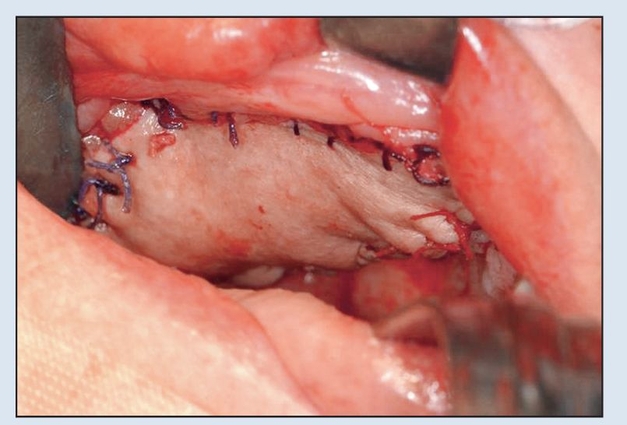
Fig 2-6d Primary closure of skin paddle achieved with 3-0 resorbable suture prior to initiation of vascular anastamosis to neck vessels.
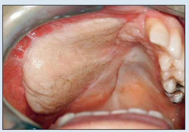
Fig 2-6e Intraoral appearance just prior to implant placement and flap thinning, approximately 5 months after placement of the fibula flap.
Stay updated, free dental videos. Join our Telegram channel
VIDEdental - Online dental courses


