Cone-Beam Computed Tomography
Volume Acquisition
William C. Scarfe and Allan G. Farman
Cone-beam computed tomographic (CBCT) imaging is the most significant technologic advance in maxillofacial imaging since the introduction of panoramic radiography. CBCT imaging was initially developed commercially for angiography in the early 1980s. It uses a divergent cone-shaped or pyramid-shaped source of ionizing radiation and a two-dimensional area detector fixed on a rotating gantry to provide multiple sequential transmission images that are integrated directly, forming volumetric information (Fig. 11-1). In the early 1990s, four technologic developments converged to facilitate construction of affordable CBCT units small enough to be used in the dental office for maxillofacial imaging:
• Introduction of x-ray detectors capable of rapid acquisition of multiple basis images
• Development of suitably high-output x-ray generators
• Evolution of suitable image acquisition and integration algorithms
The introduction of CBCT imaging has heralded a shift from a two-dimensional to a volumetric approach in maxillofacial imaging. There are three main components to CBCT imaging: (1) image production, (2) visualization, and (3) interpretation. This chapter addresses the technical issues of image production including image data set acquisition and “for presentation” reconstruction.
Principles of Cone-Beam Computed Tomographic Imaging
All computed tomographic (CT) scanners consist of an x-ray source and detector mounted on a rotating gantry (see Chapter 14). During rotation of the gantry, the x-ray source produces radiation, while the receptor records the residual x rays after attenuation by the patient’s tissues. These recordings constitute the “raw data” that is reconstructed by a computer algorithm to generate cross-sectional images. The basic component of these grayscale images is the picture element (pixel) values. The grayscale value or intensity of each pixel is related to the intensity of the photons incident on the detector. Although providing similar images, CBCT imaging represents a separate evolutionary arm to CT imaging employing multidetector computed tomographic (MDCT) imaging equipment.
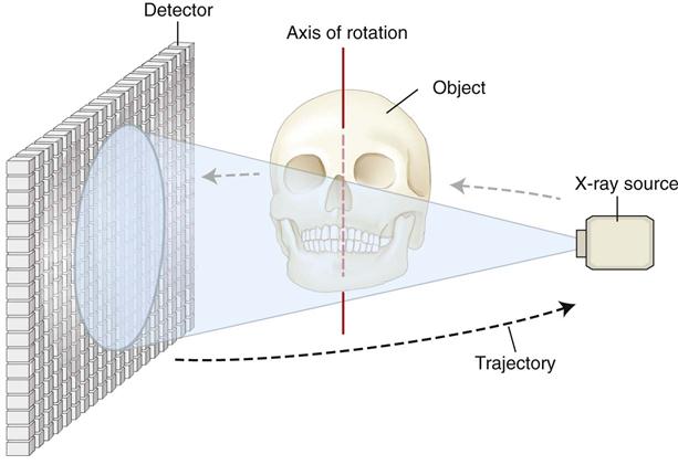
The geometric configuration and acquisition mechanics for the CBCT technique are theoretically simple (Fig. 11-2). CBCT imaging is performed using a rotating platform or gantry carrying an x-ray source and detector. A divergent cone-shaped or pyramidal source of radiation is directed through the region of interest (ROI), and the residual attenuated radiation beam is projected onto an area x-ray detector on the opposite side. The x-ray source and detector rotate around a rotation center, fixed within the center of the ROI. This rotational center becomes the center of the final acquired image volume. During the rotation, multiple sequential planar projection images are obtained while the x-ray source and detector move through an arc of 180 to 360 degrees. These single-projection images constitute the raw primary data and are individually referred to as basis, frame, or raw images. Basis images appear similar to cephalometric radiographic images except that each is slightly offset from the next. There are usually several hundred two-dimensional basis images from which the image volume is calculated and constructed. The complete series of images is referred to as the projection data. Because CBCT exposure incorporates the entire ROI, only one rotational scan of the gantry of 180 to 360 degrees is necessary to acquire enough data for volumetric image construction. Software programs incorporating sophisticated algorithms including filtered back projection are applied to these projection data to generate a volumetric data set that can be used to provide primary reconstruction images in three orthogonal planes (axial, sagittal, and coronal). Cone-beam geometry captures volumetric data quickly, and this configuration affords significant cost savings compared with MDCT imaging because multiple patients can be imaged with CBCT imaging in the time taken for one patient to be imaged with MDCT imaging.
Components of Image Production
There are three major components to CBCT image production:
The x-ray generation and detection specifications of currently available CBCT systems (Tables 11-1 and 11-2) reflect proprietary variations in these parameters.
TABLE 11-1
Summary of Specifications for Cone-Beam Computed Tomographic Systems
| Specification | Variable | Parameter |
| Unit type | Patient position during image acquisition | Supine; standing; seated |
| Functionality | CBCT only; multimodal (CBCT/pan or CBCT/pan/ceph) | |
| Geometry | Full; partial arc trajectory (degrees) | |
| Number of basis projections | Fixed; variable (number) | |
| Scan time (s) | ||
| X-ray generator | mA/kVp | Fixed; variable (settings available) |
| X-ray source | Constant; pulsed | |
| AEC | Present/absent | |
| Focal spot size | Millimeters | |
| Scan volume | Shape | Spherical; cylindrical; convex triangular; other |
| Dimensions | Diameter; height × diameter (cm) | |
| Detector | Type | II/CCD; CsI/a-Si; PST; CsI/CMOS |
| Voxel size | Fixed; variable (range) | |
| Grayscale (bit depth) | Acquired; displayed; archived (2n) | |
| Software | Primary reconstruction time | <1 min, 1-3 min, >3 min |
TABLE 11-2
Representative Cone-Beam Computed Tomographic Imaging Systems
| Products; Models | Distributor |
| 3D Accuitomo 80/170; Veraviewpocs 3D R100; Veraviewepocs 3De; Accuitomo FPD60/80 | J. Morita Mfg Corp, Kyoto, Japan |
| Art 3D/Digi-X 3D | Oy Ajat, Espoo, Finland |
| Auge/Auge Solio/Alioth/Alphard series | Asahi Roentgen, Kyoto, Japan/Belmont, Somerset, NJ |
| CB MercuRay; CB Throne | Hitachi Medical Systems, Kyoto, Japan |
| Galileos; Galileos Comfort/Compact | Sirona Dental Systems GmbH, Bensheim Germany |
| GXCB-500 HD/GXDP-700 S; KaVo 3D eXam | Gendex Dental Systems, Hatfield, PA/KaVo Dental Systems, GmbH, Bensheim Germany |
| i-CAT Classic/Next Generation/Precise | Imaging Sciences, Hatfield, PA |
| CS 9000 3D/9000 C 3D/9300/9300 Select/9500 | Carestream Dental, Atlanta, GA |
| NewTom 9000/3G/VGi/VGi-Flex/Giano/5G | QR srl,/Cefla Dental Group, Verona, Italy |
| OP300 | Instrumentarium Dental, Tuusula, Finland |
| Orion | Ritter Imaging, Ulm, Germany |
| Master 3Ds/PaX-Flex 3D/PaX-Duo 3D/PaX-Zenith 3D | VATECH Co Ltd, Gyeonggi-Do, Republic of Korea |
| PreXion 3D Elite | PreXion Inc, San Mateo, CA |
| Promax 3Ds/3D/3DMid/Max | Planmeca Oy, Helsinki, Finland |
| Scanora 3D/Cranex 3D | Soredex, Tuusulu, Finland |
| DaVinci D3D; Hyperion 9 | My-Ray Dental Imaging, Cefla Dental Group, Imola, Italy |
| Suni 3D HD | Suni Medical Imaging, Inc, San Jose, CA |
X-Ray Generation
Although CBCT imaging is technically simple in that only a single scan of the patient is made to acquire a projection data set, numerous clinically important parameters in x-ray generation affect both image quality and patient radiation dose.
Patient Stabilization
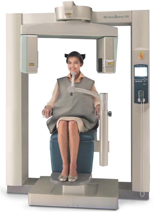
Depending on the unit, CBCT examinations are made with the patient sitting, standing, or supine. Supine units are physically larger, have a greater physical footprint, and may not be accessible for patients with some physical disabilities. Standing units may not be able to be adjusted to a height low enough to accommodate wheelchair-bound patients. Although seated units are the most comfortable, they may not allow scanning of physically disabled or wheelchair-bound patients. With all systems, immobilization of the patient’s head is more important than patient positioning because any head movement degrades the final image. Immobilization of the head is accomplished by using some combination of a chin cup, bite fork, or other head-restraint mechanism.
X-Ray Generator
During the scan rotation, each projection image set is made by sequential single-image capture of the remnant x-ray beam by the detector. X-ray generation may be continuous or pulsed to coincide with the detector activation. It is preferable to pulse the x-ray beam to coincide with the detector sampling; this means that actual exposure time is up to 50% less than scanning time. This technique reduces patient radiation dose considerably.
The ALARA (As Low As Reasonably Achievable) principle of dose optimization necessitates that CBCT exposure factors should be adjusted on the basis of patient size. This adjustment can be achieved by appropriate selection of tube current (milliamperes [mA]), tube voltage (kilovolt peak [kVp]), or both. In some cases, time also can be adjusted with faster scans producing images with fewer basis images (see later section on scan factors). Although both kVp and mA may be fixed on some units, they are automatically modulated in near real time on other units by a feedback mechanism detecting the intensity of the transmitted beam, a process known as automatic exposure control. On other units, exposure settings are automatically determined by the initial scout exposure. This feature is highly desirable because it is operator independent. The variation in exposure parameters together with the presence of pulsed x-ray beam and size of the image field are the primary determinants of patient exposure.
Scan Volume
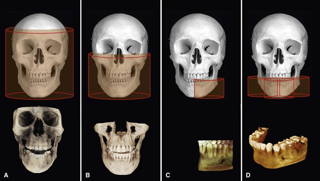
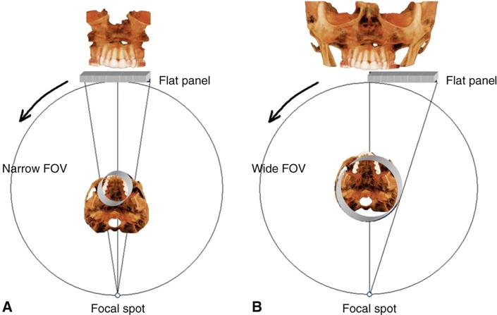
The dimensions of the field of view (FOV) or scan volume able to be covered primarily depend on the detector size and shape, the beam projection geometry, and the ability to collimate the beam. The shape of the scan volume can be either cylindrical or spherical. Collimating the primary x-ray beam limits x radiation exposure to the ROI. It is desirable to limit the field size to the smallest volume that images the ROI. This field size must be selected for each patient based on individual needs. This procedure reduces unnecessary exposure to the patient and produces the best images by minimizing scattered radiation, which degrades image quality. CBCT units are classified according to the maximum FOV incorporated from the scan or scans (Fig. 11-3).
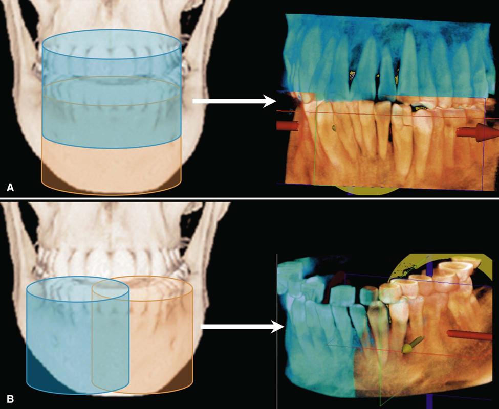
Two approaches have been introduced to enable scanning of an ROI greater than the FOV of the detector. One method involves obtaining data from two or more separate scans and superimposing the overlapping regions of the CBCT data volumes using corresponding fiducial reference landmarks (referred to as either “bioimage registration” or “mosaicing”). Software is used to fuse adjacent image volumes (“stitching” or “blending”) to create a larger volumetric data set either in the horizontal or in the vertical dimension (Fig. 11-4). The disadvantage of stitching overlapped regions is that such overlapped regions are imaged twice, resulting in double the radiation dose to such regions. A second method to increase the height or width of the FOV using a small area detector is to offset the position of the detector, collimate the beam asymmetrically, and scan only half the patient’s ROI in each of the two offset scans (Fig. 11-5).
Scan Factors
The number of images constituting the projection data throughout the scan is determined by the detector frame rate (number of images acquired per second), the completeness of the trajectory arc (180 to 360 degrees), and the rotation speed of the source and detector. The number of basis images making up a single scan set may be fixed or variable. Higher frame rates have both desirable and undesirable effects. Higher frame rates increase the signal-to-noise ratio, producing images with less noise and reducing metallic artifacts. However, a higher frame rate is associated with a longer scan time and higher patient dose. In addition, more data are obtained, and primary reconstruction time is increased.
CBCT imaging systems often use a complete circular trajectory or a scan arc to acquire adequate projection data for volumetric software reconstruction. However, increasingly, CBCT units are based on panoramic platforms, which have scan arcs less than 360 degrees. Most CBCT units have fixed scan arcs; however, some provide a choice of manual controls to reduce the scan arc further. A limited scan arc potentially reduces the scan time and patient radiation dose and is mechanically easier to perform. However, image/>
Stay updated, free dental videos. Join our Telegram channel
VIDEdental - Online dental courses


