Intraoral Projections
Intraoral radiographic (imaging) examinations are the backbone of imaging for the general dentist. Intraoral images can be divided into three categories: (1) periapical projections, (2) bitewing projections, and (3) occlusal projections. Periapical radiographs should show all of a tooth, including the surrounding bone. Bitewing images show only the crowns of teeth and the adjacent alveolar crests. Occlusal images show an area of teeth and bone larger than periapical images.
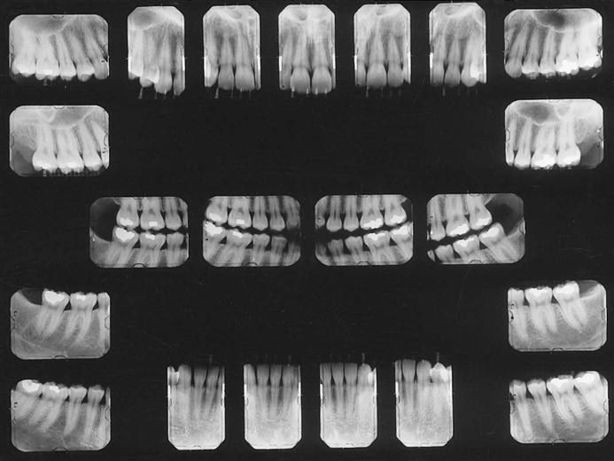
A full-mouth set of radiographs consists of periapical and bitewing projections (Fig. 7-1). These projections, when well exposed and properly processed, can provide considerable diagnostic information to complement the clinical examination. As with any clinical procedure, the operator must clearly understand the goals of dental radiography and the criteria for evaluating the quality of performance.
Images should be made only when a clear diagnostic need exists for the information the radiograph may provide. The frequency of such examinations varies with the individual circumstances of each patient (see Chapter 16).
Criteria of Quality
Every radiographic examination should produce images of optimal diagnostic quality, incorporating the following features:
When evaluating images and considering whether to retake a view, the practitioner should consider the initial reason for making the image. When a full-mouth set is indicated, it is not necessary to retake a view that fails to open a contact or show a periapical region if the missing information is available on another view. If a single view or only a few views are needed, they should be repeated only if they fail to reveal the desired information.
Periapical Imaging
Two intraoral projection techniques are commonly used for periapical imaging: (1) the paralleling technique and (2) the bisecting-angle technique. Most clinicians prefer the paralleling technique because it provides a less distorted view of the dentition. The paralleling technique is the most appropriate technique for digital imaging. The following discussion describes the principles and uses of the paralleling technique to obtain a full-mouth set of radiographs. When anatomic configuration (e.g., palate and floor of the mouth) precludes strict adherence to the paralleling concept, slight modifications may have to be made. If the anatomic constraints are extreme, some of the principles of the bisecting-angle technique may be used to accomplish the required receptor placement and determine the vertical angulation of the tube. The bisecting-angle technique is described later.
The term image receptor refers to any medium that can capture an image, including film, charge-coupled device (CCD) or complementary metal oxide semiconductor (CMOS) sensors, or storage phosphor plates. The principles for making images are the same for each of these receptor types; thus this chapter uses the general term receptor to refer any of the image receptors.
General Steps for Making an Exposure
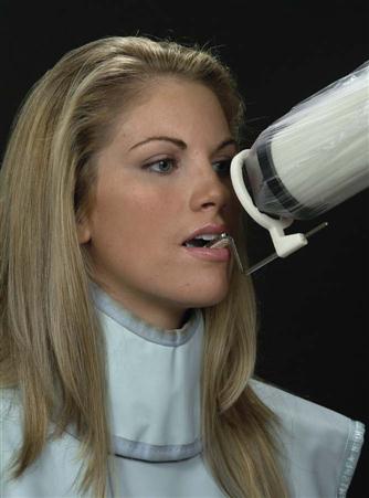
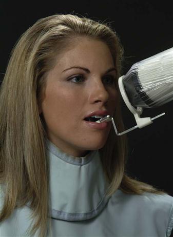
• Prepare unit for exposure. Place barriers for universal infection control (see Chapter 15) and have receptors and receptor-holding instruments ready at chairside.
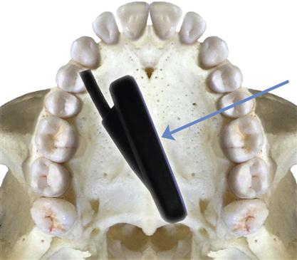
A typical full-mouth set of radiographs consists of 21 images (Box 7-1; see also Fig. 7-1). Establish a regular sequence when making exposures to avoid overlooking individual projections. Make the anterior views before the posterior views because the former views cause less discomfort for the patient. The following description of procedures pertains to the paralleling technique.
Paralleling Technique
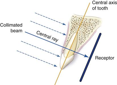
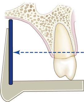
The central concept of the paralleling technique (also called the right-angle technique or long-cone technique) is that the x-ray receptor is supported parallel to the long axis of the teeth, and the central ray of the x-ray beam is directed at right angles to the teeth and receptor (Fig. 7-2). This orientation of the receptor, teeth, and central ray minimizes geometric distortion and presents the teeth and supporting bone in their true anatomic relationships. To reduce geometric distortion, the x-ray source should be located relatively distant from the teeth. The use of a long source-to-object distance reduces the apparent size of the focal spot, thus increasing image sharpness, and provides images with minimal magnification. The paralleling method works equally well for film, CCD or CMOS sensors, or storage phosphor plates.
Receptor-Holding Instruments
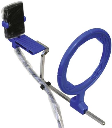
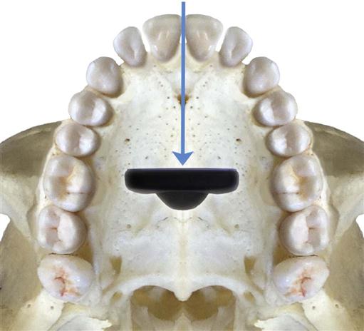
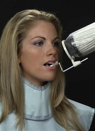
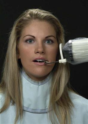
Use instruments to allow precise positions of the receptor in the patient’s mouth. Many of these receptor holders are specific for various brands of digital sensors, storage phosphor plates, or film. It is also important to use a receptor-holding instrument that has an external guiding ring. This guiding ring is used to align the x-ray aiming cylinder and ensures that the receptor is centered in the beam behind the teeth of interest and that the receptor and teeth are perpendicular to the x-ray beam (Fig. 7-3). These should be used with rectangular collimators to reduce patient exposure (see Chapter 3).
Receptor Placement
For the best images, the receptor should be positioned parallel to the teeth and deep in the patient’s mouth; this is particularly important when rigid sensors are used because they may be larger than film. For maxillary projections, the superior border of the receptor generally rests at the height of the palatal vault in the midline. Similarly, for mandibular projections, the receptor should be used to displace the tongue posteriorly or toward the midline to allow the inferior border of the receptor to rest on the floor of the mouth away from the mucosa on the lingual surface of the mandible. Especially for digital sensors, patient acceptance and comfort are best when the receptor is placed in the center of the mouth.
Angulation of the Tube Head
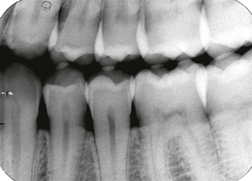
Orient the aiming cylinder of the x-ray machine in the vertical and horizontal planes to align with the aiming ring. The horizontal direction of the beam primarily influences the degree of overlapping of the images of the crowns at the interproximal spaces (Fig. 7-4).
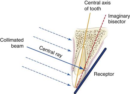
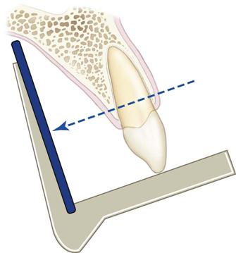
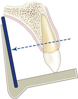
Bisecting-Angle Technique
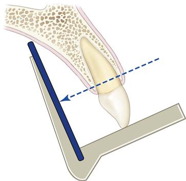
The bisecting-angle technique was used often in the first half of the twentieth century but has been largely replaced by the paralleling technique. This method may be useful when the operator is unable to apply the paralleling technique because of large rigid sensors or the anatomy of the patient. The bisecting-angle technique is based on a simple geometric theorem, Cieszynski’s rule of isometry, which states that two triangles are equal when they share one complete side and have two equal angles. Dental radiography applies the theorem as follows. The receptor is positioned as close as possible to the lingual surface of the teeth, resting in the palate or in the floor of the mouth (Fig. 7-5). The plane of the receptor and the long axis of the teeth form an angle with its apex at the point where the receptor is in contact with the teeth along an imaginary line that bisects this angle and directs the central ray of the beam at right angles to this bisector. This forms two triangles with two equal angles and a common side (the imaginary bisector). Consequently, when these conditions are satisfied, the images cast on the receptor theoretically are the same length as the projected object. To reproduce the length of each root of a multirooted tooth accurately, the central beam must be angled differently for each root. Another limitation of this technique is that the alveolar ridge often projects more coronally than its true position, thus distorting the apparent height of the alveolar bone around the teeth.
Receptor-Holding Instruments
Several methods can be used to support receptors intraorally for bisecting-angle projections. The preferred method is to use a receptor-holding, bisecting-angle instrument that provides an external device for localizing the x-ray beam. The bisecting-angle instrument uses a fixed average bisecting angle. It is undesirable to have the patient support the receptor from the lingual surface with his or her forefinger. Patients often use excessive force and bend the receptor, causing distortion of the image. Also, the receptor might slip without the operator’s expertise, resulting in an improper image field. Finally, without an external guide to the position of the receptor, the x-ray beam may miss part of the receptor, resulting in a partial image (cone cut).
Positioning of the Patient
For images of the maxillary arch, the patient’s head should be positioned upright with the sagittal plane vertical and the occlusal plane horizontal. When the mandibular teeth are to be radiographed, the head is tilted back slightly to compensate for the changed occlusal plane when the mouth is opened.
Receptor Placement
The projections described for the paralleling technique may also be used for the bisecting-angle technique. The receptor is positioned behind the area of interest, with the apical end against the mucosa on the lingual or palatal surface. The occlusal or incisal edge is oriented against the teeth with an edge of the receptor extending just beyond the teeth. If necessary for the patient’s comfort, the anterior corner of a film can be softened by bending it before it is placed against the mucosa. Care must be taken not to bend the film excessively because this may result in considerable image distortion and pressure defects in the emulsion that are apparent on the processed film. Such bending is impossible with CCD or CMOS sensors or storage phosphor plates.
Angulation of the Tube Head
Horizontal Angulation.
When a receptor-holding device with a beam-localizing ring is used, the instrument is positioned horizontally so that when the tube is aligned with the ring, the central ray is directed through the contacts in the region being examined. If the receptor-holding device does not have a beam-localizing feature, the tube is pointed so as to direct the central ray through the contacts. In this situation, the radiation beam is also centered on the receptor. This angulation usually is at right angles (in the horizontal projection) to the buccal or facial surfaces of the teeth in each region.
Vertical Angulation.
In practice, the clinician’s goal is to aim the central ray of the x-ray beam at right angles to a plane bisecting the angle between the receptor and the long axis of the tooth. This principle works well with flat, two-dimensional structures, but teeth that have depth or are multirooted show evidence of distortion. Excessive vertical angulation results in foreshortening of the image, whereas insufficient vertical angulation results in image elongation. The angle that directs the central ray perpendicular to the bisecting plane varies with the individual’s anatomy. Several measurements can be used as a general guide when the occlusal plane is oriented parallel with the floor (Table 7-1).
Paralleling Technique •
Maxillary Central Incisor Projection*
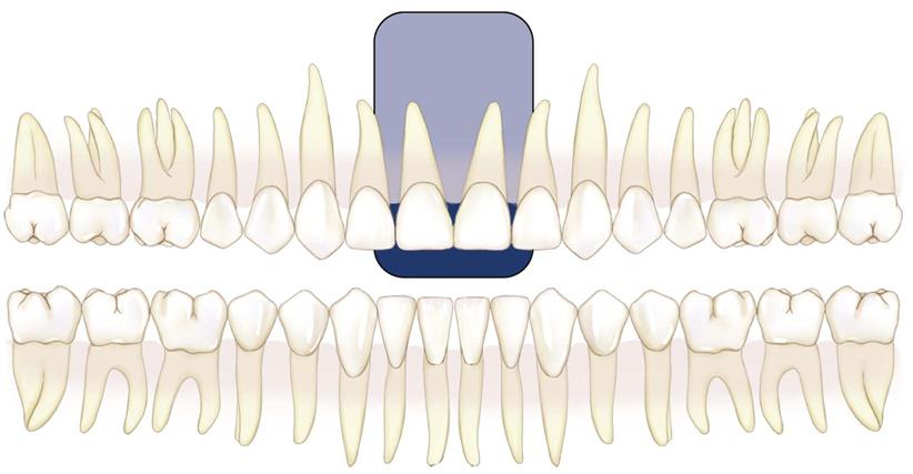
Image Field.
The field of view on these radiographs (shaded area) should include both central incisors and their periapical areas.
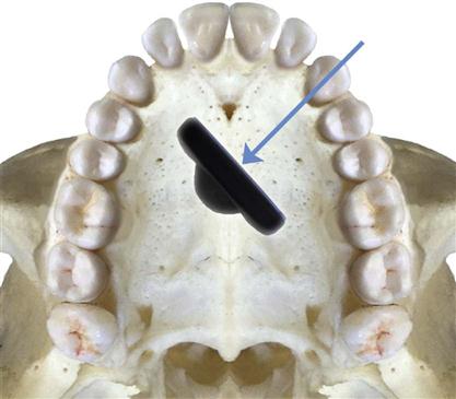
Receptor Placement.
Place a No. 1 receptor at about the level of the second premolars or first molars to take advantage of the maximal palatal height so that the entire length of the teeth can be projected on it. Have the receptor resting on the palate with its midline centered with the midline of the arch. Position the packet’s long axis parallel to the long axis of the maxillary central incisors.
Projection of Central Ray.†
Direct the central ray through the contact point of the central incisors and perpendicular to the plane of the receptors and roots of the teeth. Because the axial inclination of the maxillary incisors is about 15 to 20 degrees, the vertical angulation of the tube should be at the same positive angle. The tube should have 0 horizontal angulation.
Point of Entry.
Direct the point of entry of the central ray high on the lip, in the midline, just below the septum of the nostril. If the palatal vault is unusually low or a palatal torus is present, it may be necessary to tilt the receptor holder positively and compromise a completely parallel relationship between the receptor and the teeth to ensure that the periapical region is included on the image.
Paralleling Technique •
Maxillary Lateral Projection
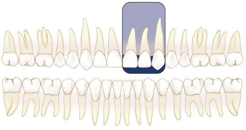
Image Field.
This projection should show the lateral incisor and its periapical field centered on the radiograph. Include the mesial interproximal area with the distal aspect of the central incisor on the radiograph so that no overlap is evident.

Receptor Placement.
Place a No. 1 receptor deep in the oral cavity parallel with the long axis and the mesiodistal plane of the maxillary lateral incisor.
Projection of Central Ray.
Direct the central ray through the middle of the lateral incisor, with no overlapping of the margins of the crowns at the interproximal space on its mesial aspect. Do not attempt to visualize the distal contact with the canine.
Point of Entry.
Orient the central ray to enter high on the lip about 1 cm from the midline.
Paralleling Technique •
Maxillary Canine Projection
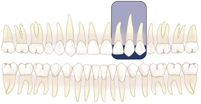
Image Field.
This projection should demonstrate the entire canine, with its periapical area, in the midline of the radiograph. Open the mesial contact area. Ignore the distal contact because it will be visualized on other projections.
Receptor Placement.
Place a No. 1 receptor against the palate, well away from the palatal surface of the teeth. Orient the receptor packet with its anterior edge at about the middle of the lateral incisor and its long axis parallel with the long axis of the canine.
Projection of Central Ray.
Position the holding instrument so that it directs the beam through the mesial contact of the canine. Do not attempt to open the distal contact.
Point of Entry.
Direct the central ray through the canine eminence. The point of entry is at about the intersection of the distal and inferior borders of the ala of the nose.
Paralleling Technique •
Maxillary Premolar Projection
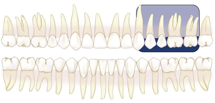
Image Field.
The radiograph of this region should include the images of the distal half of the canine and the premolars, with room for at least the first molar.
Receptor Placement.
Place a No. 2 receptor in the mouth with the long dimension parallel with the occlusal plane and in the midline and near the palatal midline. The packet should extend far enough forward to cover the distal half of the canine. It should also include the premolars and the first molar and maybe the mesial portion of the second molar. The plane of the receptor should be nearly vertical to correspond with the long axis of the premolar teeth. Position the receptor-holding device so that the long axis of the receptor is parallel with the mean buccal plane of the premolars. This establishes the proper horizontal angulation.
Projection of Central Ray.
Direct the central ray perpendicular to the receptor. The horizontal angulation of the holding instrument should be adjusted to permit the beam to pass through the interproximal area between the first and second premolars.
Point of Entry.
Place the holding instrument so that the central ray passes through the center of the second premolar root. This point usually is below the pupil of the eye.
Stay updated, free dental videos. Join our Telegram channel
VIDEdental - Online dental courses


