Extraoral Projections and Anatomy
Sotirios Tetradis and Mel L. Kantor
In extraoral radiographic examinations, both the x-ray source and the image receptor (film or electronic sensor) are placed outside the patient’s mouth. This chapter describes the most common extraoral radiographic examinations in which the source and sensor remain static. These include the lateral cephalometric projection of the sagittal or median plane; the submentovertex (SMV) projection of the transverse or horizontal plane; and the Waters, posteroanterior (PA) cephalometric, and reverse-Towne projections of the coronal or frontal plane. Panoramic radiography is described in Chapter 10, and other more complex imaging modalities are described in Chapters 11 through 14.
Selection Criteria
Extraoral radiographs are used to examine areas not fully covered by intraoral films or to evaluate the cranium, face (including the maxilla and mandible), or cervical spine for diseases, trauma, or abnormalities. Standardized extraoral (cephalometric) radiographs also assist in evaluating the relationship between various orofacial and dental structures, growth and development of the face, or treatment progression.
Before obtaining an extraoral radiograph, it is essential to evaluate the patient’s complaints and clinical signs in detail. The clinician first must decide which anatomic structures need to be evaluated and then select the appropriate projection or projections. Selecting the appropriate extraoral radiographic examination for the diagnostic task at hand is the first step in obtaining and interpreting a radiograph. For spatially localizing pathology, usually at least two radiographs taken at right angles to each another are obtained.
Technique
Extraoral radiographs are produced with conventional dental x-ray machines, certain models of panoramic machines, or higher capacity medical x-ray units. Cephalometric and skull views require at least a 20 cm × 25 cm (8 inch × 10 inch) image receptor. It is critical to label the right and left sides of the image correctly and clearly. This usually is done by placing a metal marker (an R or an L) on the outside of the cassette in a corner in which the marker does not obstruct diagnostic information.
The proper exposure parameters depend on the patient’s size, anatomy, and head orientation; image receptor speed; x-ray source-to-receptor distance; and whether or not grids are used. In cases of known or suspected disease, medium-speed or high-speed rare-earth screen-film combinations provide optimal balance between diagnostic information and patient exposure. For orthodontic purposes, high-speed combinations reduce patient exposure without compromising the identification of anatomic landmarks necessary for cephalometric analysis. Although radiographic grids reduce scattered radiation and improve contrast and resolution, they result in higher patient exposure. Cephalometry does not require the use of grids. However, grids could improve the radiographic appearance of fine structures, such as trabecular architecture, and aid in the diagnosis of disease.
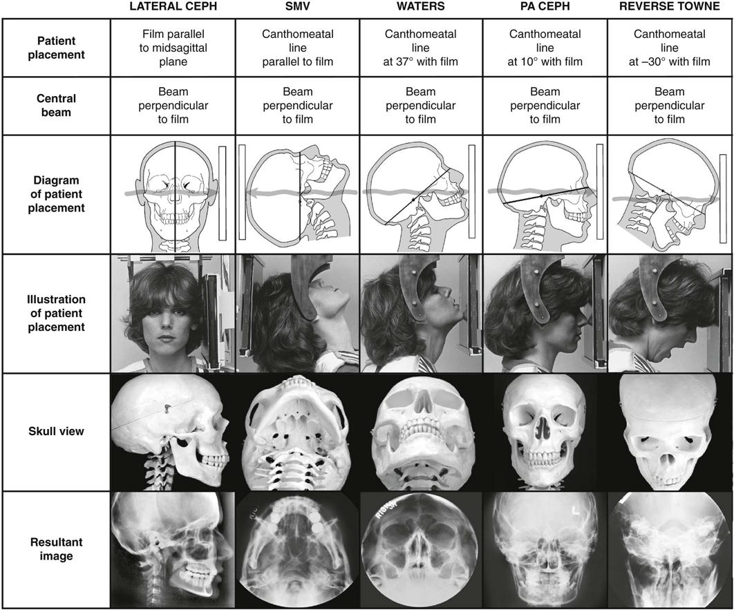
Proper positioning of the x-ray source, patient, and image receptor requires patience, attention to detail, and experience. The main anatomic landmark used in patient positioning during extraoral radiography is the canthomeatal line, which joins the central point of the external auditory canal to the outer canthus of the eye. The canthomeatal line forms approximately a 10-degree angle with the Frankfort plane, the line that connects the superior border of the external auditory canal with the infraorbital rim. The image receptor and patient placement, central beam direction, and resultant image for the lateral, submentovertex, Waters, posteroanterior, and reverse-Towne projections are summarized in Table 9-1 and are described in detail in the text. Table 9-1 is organized to show the progressive head rotation in relation to the x-ray beam in the frontal views and thus clarify the resultant projected anatomy.
Evaluation of the Image
Extraoral images should first be evaluated for overall quality. Proper exposure and processing result in an image with good contrast and density. Proper patient positioning prevents unwanted superimpositions and distortions and facilitates identification of anatomic landmarks. Interpreting poor-quality images can lead to diagnostic errors and subsequent treatment errors.
The first step in the interpretation of radiographic images is the identification of anatomy. A thorough knowledge of normal radiographic anatomy and the appearance of normal variants is critical for the identification of pathology. Abnormalities cause disruptions of normal anatomy. Detecting the altered anatomy precedes classifying the type of change and developing a differential diagnosis. What is not detected cannot be interpreted.
Interpretation of extraoral radiographs should be thorough, careful, and meticulous. Images should be interpreted in a room with reduced ambient light, and peripheral light from the viewbox or monitor should be masked. A systematic, methodical approach should be used for the visual exploration or interrogation of the diagnostic image. A method for the visual interrogation of extraoral radiograph of the head and neck is illustrated for the lateral and PA projections but can be applied to the remaining projections as well. These methods are not the only approach to examining radiographic images. Any technique that reliably ensures that the entire image will be examined is equally appropriate.
Lateral Skull Projection (Lateral Cephalometric Projection)
Of the extraoral radiographs described in this chapter, the lateral cephalometric projection is the most commonly used in dentistry. All cephalometric radiographs, including the lateral view, are taken with a cephalostat that helps maintain a constant relationship among the skull, the film, and the x-ray beam. Skeletal, dental, and soft tissue anatomic landmarks delineate lines, planes, angles, and distances that are used to generate measurements and to classify patients’ craniofacial morphology. At the beginning of treatment, these measurements are often compared with an established standard; during treatment, the measurements are usually compared with measurements from previous cephalometric radiographs of the same patient to monitor growth and development as well as treatment.
Image Receptor and Patient Placement
The image receptor is positioned parallel to the patient’s midsagittal plane. The site of interest is placed toward the image receptor to minimize distortion. In cephalometric radiography, the patient is placed with the left side toward the image receptor (U.S. standards), and a wedge filter at the tube head is positioned over the anterior aspect of the beam to absorb some of the radiation and allow visualization of soft tissues of the face. Additional information about lateral cephalometry is provided at the end of this section.
Position of Central X-Ray Beam
The central beam is perpendicular to the midsagittal plane of the patient and the plane of the image receptor and is centered over the external auditory meatus.
Resultant Image (Fig. 9-1)
Exact superimposition of right and left sides is impossible because the structures on the side near to the image receptor are magnified less than the same structures on the side far from the image receptor. Bilateral structures close to the midsagittal plane demonstrate less discrepancy in size compared with bilateral structures farther away from the midsagittal plane. Structures close to the midsagittal plane (e.g., the clinoid processes and inferior turbinates) should be nearly superimposed.
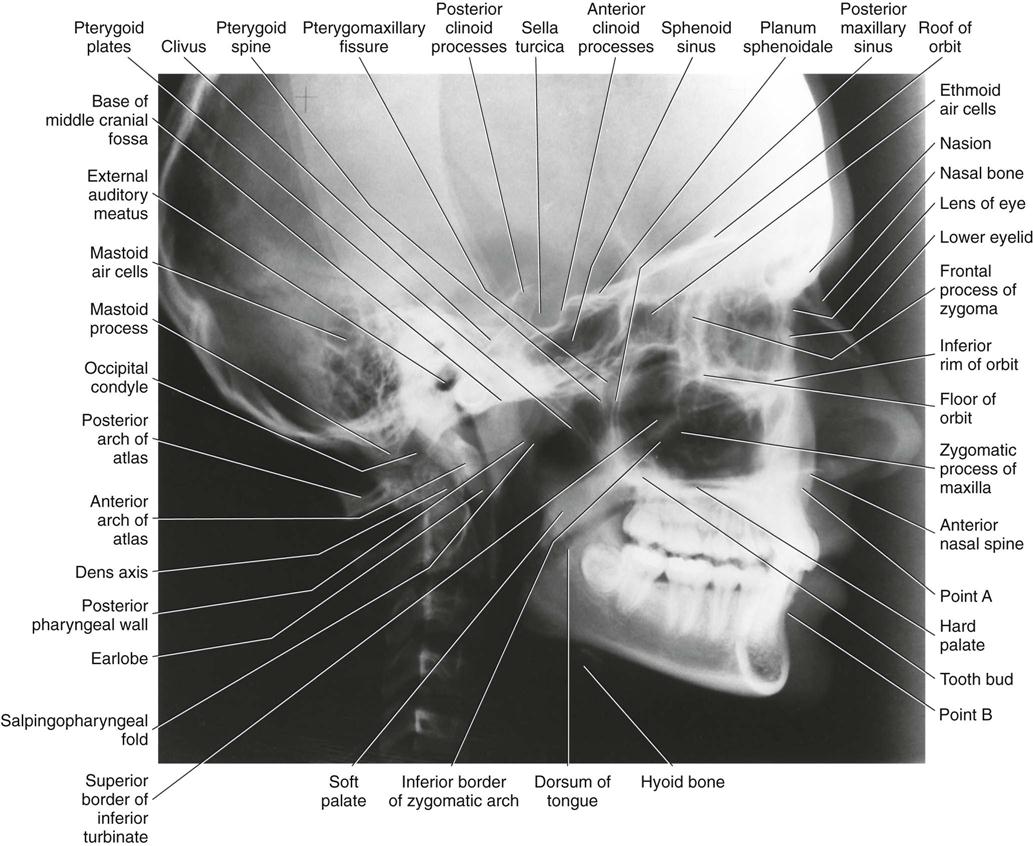
Interpretation
Although the lateral cephalometric radiograph is obtained to evaluate the relationship of the oral and facial structures, this radiograph is still a lateral skull film providing significant diagnostic information for the head and neck anatomy. As such, lateral cephalometric radiographs should first be evaluated for possible pathology and for anatomic variants that might simulate disease, before cephalometric analysis. It is not sufficient to limit the interpretation to the cephalometric analysis. To ensure that all anatomic structures are assessed, a systematic visual interrogation of lateral cephalometric radiographs should be followed. Such an approach is presented next (Fig. 9-2):
Stay updated, free dental videos. Join our Telegram channel
VIDEdental - Online dental courses


