Projection Geometry
A conventional radiograph is made with a stationary x-ray source and displays a two-dimensional image of a part of the body. Such images are often called plain or projection views (in contrast to ultrasound, computed tomography [CT], magnetic resonance imaging, or nuclear medicine). In plain views, the entire volume of tissue between the x-ray source and the image receptor (digital sensor or film) is projected onto a two-dimensional image. To obtain the maximal value from a radiograph, a clinician must have a clear understanding of normal anatomy and mentally reconstruct a three-dimensional image of the anatomic structures of interest from one or more of these two-dimensional views. Using high-quality radiographs greatly facilitates this task. The principles of projection geometry describe the effect of focal spot size and relative position of the object and image receptor (digital sensor or film) on image clarity, magnification, and distortion. Clinicians use these principles to maximize image clarity, minimize distortion, and localize objects in the image field.
Image Sharpness and Resolution
Several geometric considerations contribute to image sharpness and spatial resolution. Sharpness measures how well a boundary between two areas of differing radiodensity is revealed. Image spatial resolution measures how well a radiograph is able to reveal small objects that are close together. Although sharpness and resolution are two distinct features, they are interdependent, being influenced by the same geometric variables. For clinical diagnosis, it is desirable to optimize conditions that result in images with high sharpness and resolution.
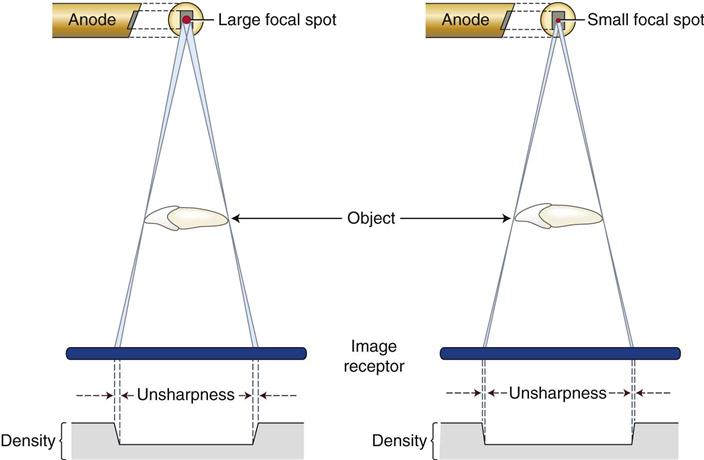
When x rays are produced at the target in an x-ray tube, they originate from all points within the area of the focal spot. Because these rays originate from different points and travel in straight lines, their projections of a feature of an object do not occur at exactly the same location on an image receptor. As a result, the image of the edge of an object is slightly blurred rather than sharp and distinct. Figure 6-1 shows the path of photons that originate at the margins of the focal spot and provide an image of the edges of an object. The resulting blurred zone of unsharpness on an image causes a loss in image sharpness. The larger the focal spot area, the greater the unsharpness.
There are three means to maximize image sharpness:
1. Use as small an effective focal spot as practical. Dental x-ray machines preferably should have a effective focal spot size of 0.4 mm because this greatly adds to image clarity. As described in Chapter 1, the size of the effective focal spot is a function of the angle of the target with respect to the long axis of the electron beam. A large angle distributes the electron beam over a larger surface and decreases the heat generated per unit of target area, thus prolonging tube life; however, this results in a larger effective focal spot and loss of image clarity (Fig. 6-2). A small angle has a greater wearing effect on the target but results in a smaller effective focal spot and increased image sharpness.
2. Increase the distance between the focal spot and the object by using a long, open-ended cylinder. Figure 6-3 shows how increasing the focal spot-to-object distance reduces image blurring by reducing the divergence of the x-ray beam. A longer focal spot-to-object distance minimizes blurring by using photons whose paths are almost parallel. The benefits of using a long focal spot-to-object distance support the use of long, open-ended cylinders as aiming devices on dental x-ray machines.
3. Minimize the distance between the object and the image receptor. Figure 6-4 shows that, as the object-to-image receptor distance is reduced, the zone of unsharpness decreases, resulting in enhanced image clarity. This is the result of minimizing the divergence of the x-ray photons.
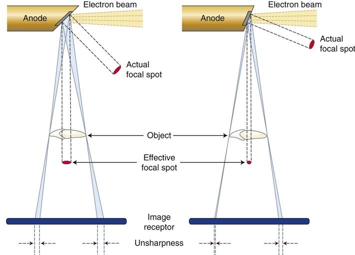
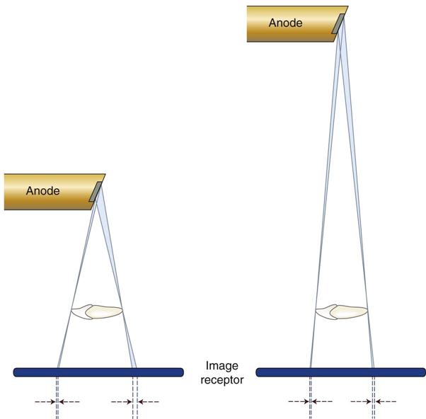
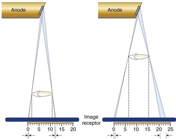
Image Size Distortion
Image size distortion (magnification) is the increase in size of the image on the radiograph compared with the actual size of the object. The divergent paths of photons in an x-ray beam cause enlargement of the image on a radiograph. Image size distortion results from the relative distances of the focal spot-to-image receptor and object-to-image receptor (see Figs. 6-3 and 6-4). Increasing the focal spot-to-image receptor distance and decreasing the object-to-image receptor distance minimizes image magnification. The use of a long, open-ended cylinder as an aiming device on an x-ray machine thus reduces the magnification of images on a periapical view. As previously mentioned, this technique also improves image sharpness by increasing the distance between the focal spot and the object.
Image Shape Distortion
Image shape distortion is the result of unequal magnification of different parts of the same object. This situation arises when not all the parts of an object are at the same focal spot-to-object distance. The physical shape of the object may often prevent its optimal orientation, resulting in some shape distortion. Such a phenomenon is seen by the differences in appearance of the image on a radiograph compared with the true shape. To minimize shape distortion, the practitioner should make an effort to align the tube, object, and image receptor carefully according to the following guidelines:
1. Position the image receptor parallel to the long axis of the object. Image shape distortion is minimized when the long axes of the image receptor and tooth are parallel. Figure 6-5 shows that the central ray of the x-ray beam is perpendicular to the image receptor, but the object is not parallel to the image receptor. The resultant image is distorted because of the unequal distances of the various parts of the object from the image receptor. This type of shape distortion is called foreshortening because it causes the radiographic image to be shorter than the object. Figure 6-6 shows the situation when the x-ray beam is oriented at right angles to the object but not to the image receptor; this results in elongation, with the object appearing longer on the image receptor than its actual length.
Stay updated, free dental videos. Join our Telegram channel
VIDEdental - Online dental courses


