Film Imaging
A beam of x-ray photons that passes through the dental arches is reduced in intensity (attenuated) by absorption and scattering of photons out of the primary beam. The pattern of the photons that exits the patient, the remnant beam, conveys information about the patient’s anatomy. For this information to be useful diagnostically, the remnant beam must be recorded on an image receptor. The image receptor most often used in dental radiography is x-ray film. This chapter describes x-ray film and film processing and the use of intensifying screens. Digital radiographic systems, which also may be used to make radiographs, are described in Chapter 4.
X-Ray Film
Composition
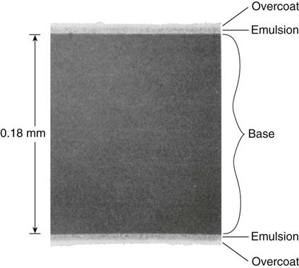
X-ray film has two principal components: (1) emulsion and (2) base. The emulsion, which is sensitive to x rays and visible light, records the radiographic image. The base is a plastic supporting material onto which the emulsion is coated (Fig. 5-1).
Emulsion
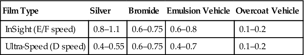
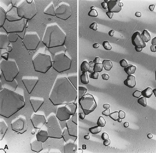
The two principal components of emulsion are silver halide grains, which are sensitive to x radiation and visible light, and a vehicle matrix in which the crystals are suspended. The silver halide grains are composed primarily of crystals of silver bromide. The composition of a dental film emulsion is shown in Table 5-1. The silver halide grains in INSIGHT film and Ultra-speed film (Carestream Dental, a division of Carestream Health, Inc.) are flat, tabular crystals with a mean diameter of about 1.8 µm (Fig. 5-2). The tabular grains are oriented parallel with the film surface to offer a large cross-sectional area to the x-ray beam (Fig. 5-3). INSIGHT film has about twice the number of silver grains so that it requires only half the exposure of Ultra-speed film.
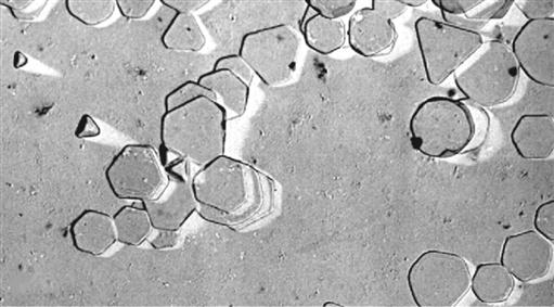
TABLE 5-1
Typical Coating Weights per Film Side (mg/cm2)
| Film Type | Silver | Bromide | Emulsion Vehicle | Overcoat Vehicle |
| InSight (E/F speed) | 0.8–1.1 | 0.6–0.75 | 0.6–0.8 | 0.1–0.2 |
| Ultra-Speed (D speed) | 0.4–0.55 | 0.6–0.75 | 0.4–0.7 | 0.1–0.2 |
Data from Carestream Health, Inc., exclusive manufacturer of Kodak dental systems.
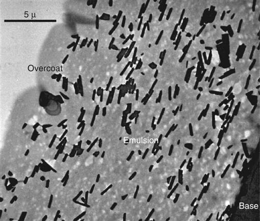
The silver halide grains are suspended in a surrounding vehicle that is applied to both sides of the supporting base. During film processing (described later in this chapter) the vehicle absorbs processing solutions, allowing the chemicals to reach and react with the silver halide grains. An additional layer of vehicle is added to the film emulsion as an overcoat. This barrier helps protect the film from damage by scratching, contamination, or pressure from rollers when an automatic processor is used.
Film emulsions are sensitive to both x-ray photons and visible light. Film intended to be exposed by x rays is called direct exposure film. All intraoral dental film is direct exposure film. Screen film is used with intensifying screens (described later in this chapter) that emit visible light. Screen film and intensifying screens are used for extraoral projections, such as panoramic and cephalometric radiographs.
Base
The function of the film base is to support the emulsion. The base for dental x-ray film is made of polyester polyethylene terephthalate, which provides the proper degree of flexibility to allow easy handling of the film. The film base must also withstand exposure to processing solutions without becoming distorted. The base is uniformly translucent and casts no pattern on the resultant radiograph.
Intraoral X-Ray Film
Intraoral dental x-ray film is made as a double-emulsion film—that is, both sides of the base are coated with an emulsion. With a double layer of emulsion, less radiation is required to produce an image. Direct exposure film is used for intraoral examinations because it provides higher resolution images than screen-film combinations. Some diagnostic tasks, such as detection of incipient caries or early periapical disease, require this higher resolution.
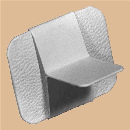
One corner of each dental film has a small, raised dot that is used for film orientation (Fig. 5-4). The manufacturer orients the film in the packet so that the convex side of the dot is toward the front of the packet and faces the x-ray tube. The side of the film with the depression is thus oriented toward the patient’s tongue. After the film has been exposed and processed, the dot is used to orient the patient’s right and left side images properly. When mounting radiographs, each film is oriented with the convex side of the dot toward the viewer, and on the basis of the features of the teeth and anatomic landmarks in the adjacent bone, the films are arranged in their normal sequential relationship in the mount.
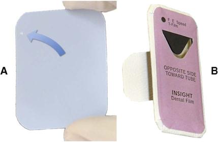
Intraoral x-ray film packets contain either one or two sheets of film (Fig. 5-5). When double-film packs are used, the second film serves as a duplicate record that can be sent to insurance companies or to a colleague. The film is encased in a protective black paper wrapper and then in an outer white paper or plastic wrapping, which is resistant to moisture. The outer wrapping clearly indicates the location of the raised dot and identifies which side of the film should be directed toward the x-ray tube.
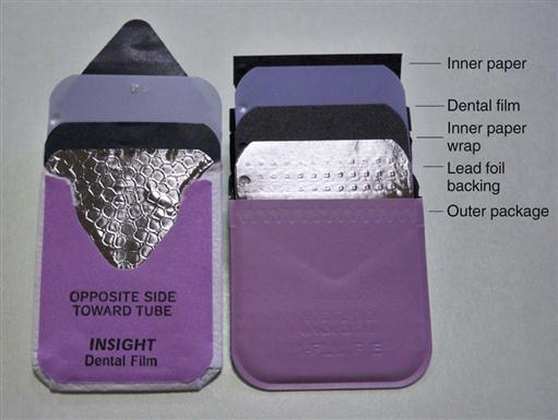
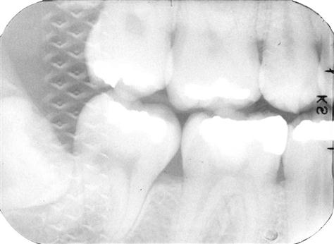
A thin lead foil backing with an embossed pattern is between the wrappers in the film packet. The foil is positioned in the film packet behind the film, away from the tube. This lead foil serves several purposes. It shields the film from backscatter (secondary) radiation, which fogs the film and reduces subject contrast (image quality). It also reduces patient exposure by absorbing some of the residual x-ray beam. Most importantly, if the film packet is placed backward in the patient’s mouth so that the tube side of the film is facing away from the x-ray machine, the lead foil will be positioned between the subject and the film. In this circumstance, most of the radiation is absorbed by the lead foil, and the resulting radiograph is light and shows the embossed pattern in the lead foil (Fig. 5-6). This combination of a light film with the characteristic pattern indicates that the film packet was exposed backward in the patient’s mouth and that the patient’s right side–left side designation indicated by the film dot is reversed.
Periapical View
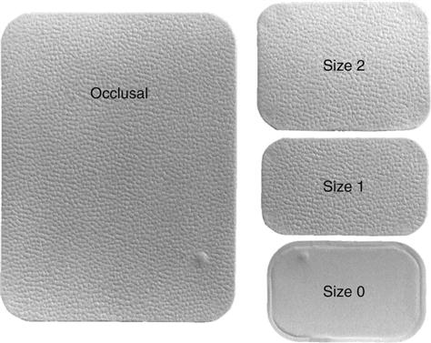
Periapical views are used to record the crowns, roots, and surrounding bone. Film packs come in three sizes: (1) size 0 for small children (22 mm × 35 mm); (2) size 1, which is relatively narrow and used for views of the anterior teeth (24 mm × 40 mm); and (3) size 2, the standard film size used for adults (30.5 mm × 40.5 mm) (Fig. 5-7).
Bitewing View
Bitewing (interproximal) views are used to record the coronal portions of the maxillary and mandibular teeth in one image. They are useful for detecting interproximal caries and evaluating the height of alveolar bone. Size 2 film is normally used in adults; the smaller size 1 is preferred in children. In small children, size 0 may be used. A relatively long size 3 is also available.
Bitewing films often have a paper tab projecting from the middle of the film on which the patient bites to support the film (Fig. 5-8). This tab is rarely visualized and does not interfere with the diagnostic quality of the image. Film-holding instruments for bitewing projections also are available.
Occlusal View
Occlusal film, size 4, is more than three times larger than size 2 film (see Fig. 5-7). It is used to show larger areas of the maxilla or mandible than may be seen on a periapical film. These films also are used to obtain right-angle views to the usual periapical view. The name derives from the fact that the film is held in position by having the patient bite lightly on it to support it between the occlusal surfaces of the teeth (see Chapter 7).
Screen Film
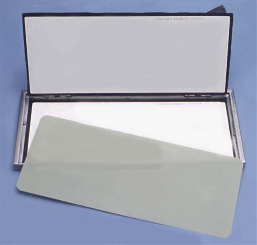
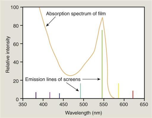
The extraoral projections used most frequently in dentistry are panoramic and cephalometric views. For these projections, screen film is used with intensifying screens (described later in this chapter) to reduce patient exposure (Fig. 5-9). Screen film is different from dental intraoral film. It is designed to be sensitive to visible light because it is placed between two intensifying screens when an exposure is made. The intensifying screens absorb x rays and emit visible light, which exposes the film. Silver halide crystals are inherently sensitive to ultraviolet (UV) and blue light (300 to 500 nm) and thus are sensitive to screens that emit UV and blue light. When film is used with screens that emit green light, the silver halide crystals are coated with sensitizing dyes to increase absorption. It is important to use the appropriate screen-film combination recommended by the screen and film manufacturer so that the emission characteristics of the screen match the absorption characteristics of the film.
Contemporary screen films use tabular-shaped (flat) grains of silver halide (Fig. 5-10) to capture the image. The tabular grains are oriented with their relatively large, flat surfaces facing the radiation source, providing a larger cross section (target) and resulting in increased speed without loss of sharpness. To increase the sharpness of images, some manufacturers add an absorbing dye in the film emulsion. This dye reduces light from one screen crossing through the film to reach the emulsion on the opposite side. EVG film from Carestream Dental is an example of this type of film.
Intensifying Screens
Early in the history of radiography, scientists discovered that various inorganic salts or phosphors fluoresce (emit visible light) when exposed to an x-ray beam. The intensity of this fluorescence is proportional to the x-ray energy absorbed. These phosphors are incorporated into intensifying screens for use with screen film. The sum of the effects of the x rays and the visible light emitted by the screen phosphors exposes the film in an intensifying cassette (see Fig. 5-9).
Function
The presence of intensifying screens creates an image receptor system that is 10 to 60 times more sensitive to x rays than the film alone. Consequently, use of intensifying screens substantially reduces the dose of x radiation to the patient. Intensifying screens are used with films for virtually all extraoral radiography, including panoramic, cephalometric, and skull projections. Generally, the resolving power of screens is related to their speed: the slower the speed of a screen, the greater its resolving power, and vice versa. Intensifying screens are not used intraorally with periapical or occlusal films because their use would reduce the resolution of the resulting image below that necessary for diagnosis of much dental disease.
Composition
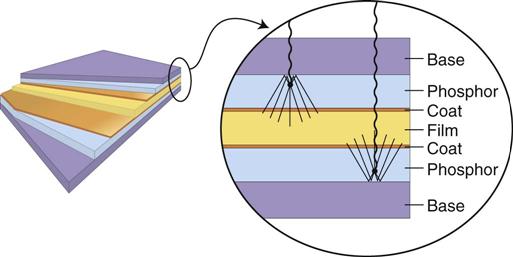
Intensifying screens are made of a base supporting material, a phosphor layer, and a protective polymeric coat (Fig. 5-11). In all dental applications, intensifying screens are used in pairs, one on each side of the film, and they are positioned inside a cassette (see Fig. 5-9). The purpose of a cassette is to hold each intensifying screen in contact with the x-ray film to maximize the sharpness of the image.
Base
The base material of most intensifying screens is some form of polyester plastic that is about 0.25 mm thick. The base provides mechanical support for the other layers. In some intensifying screens, the base also is reflective; thus it reflects light emitted from the phosphor layer back toward the x-ray film. This reflective base increases the light emission of the intensifying screen but also results in some image “unsharpness” because of the divergence of light rays reflected back to the film.
Phosphor Layer
The phosphor layer is composed of phosphorescent crystals suspended in a polymeric binder. When the crystals absorb x-ray photons, they fluoresce (see Fig. 5-11). The phosphor crystals often contain rare earth elements, most commonly lanthanum and gadolinium. Their fluorescence can be increased by the addition of small amounts of elements, such as thulium, niobium, or terbium. Common phosphor combinations used in intensifying screens are shown in Table 5-2. Rare earth screens convert each absorbed x-ray photon into about 4000 lower energy, visible light (green or blue) photons. These visible photons expose the film.
TABLE 5-2
Rare Earth Elements Used in Intensifying Screens
| Emission | Phosphor |
| Green | Gadolinium oxysulfide, terbium activated |
| Blue and UV | Yttrium tantalite, niobium activated |
Different phosphors fluoresce in different portions of the spectrum. For example, light emission from Lanex rare earth intensifying screens ranges from 375 to 600 nm and peaks sharply at 545 nm (green). Figure 5-12 shows the spectral emission of a rare earth screen and the spectral sensitivity of an appropriate film. Other intensifying screens have a major peak at 350 nm (UV) and at 450 nm (blue). It is important to match green-emitting screens with green-sensitive films and blue-emitting screens with blue-sensitive films.
Fast screens have large phosphor crystals and efficiently convert x-ray photons to visible light but produce images with lower resolution. As the size of the crystals or the thickness of the screen decreases, the speed of the screen also declines, but image sharpness increases. Fast screens also have a thicker phosphor layer and a reflective layer, but these properties also decrease sharpness. In deciding on the combination to use, the practitioner must consider the resolution requirements of the task for which the image will be used. Screen-film combinations are rated for speed, a measure of the amount of radiation required for a proper exposure. For dental extraoral diagnostic tasks, it is recommended to use screen-film combinations that have a speed of 400 or faster.
Protective Coat
A protective polymer coat (≤15 µm thick) is placed over the phosphor layer to protect the phosphor and to provide a surface that can be cleaned. The intensifying screens should be routinely cleaned because any debris, spots, or scratches may cause light spots on the resultant radiograph.
Formation of the Latent Image
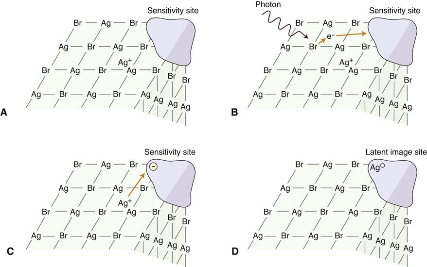
When a beam of photons exits an object and exposes an x-ray film (either direct-exposure film or screen film exposed by light photons), it chemically changes the photosensitive silver halide crystals in the film emulsion. These chemically altered silver bromide crystals constitute the latent (invisible) image on the film. Before exposure, film emulsion consists of photosensitive crystals containing primarily silver bromide (Fig. 5-13, A). These silver halide crystals also contain a few free silver ions (interstitial silver ions) and trace amounts of sulfur compounds bound to the surface of the crystals. Along with physical irregularities in the crystal produced by iodide ions, sulfur compounds create sensitivity sites, sites in the crystals that are sensitive to radiation. Each crystal has many sensitivity sites. When the silver halide crystals are irradiated, x-ray photons release electrons from the bromide ions (Fig. 5-13, B). The free electrons move through the crystal until they reach a sensitivity site, where they become trapped and impart a negative charge to the site. The negatively charged sensitivity site attracts positively charged free interstitial silver ions (Fig. 5-13, C). When a silver ion reaches the negatively charged sensitivity site, it is reduced and forms a neutral atom of metallic silver (Fig. 5-13, D). The sites containing these neutral silver atoms are now called latent image sites. This process occurs numerous times within a crystal. The overall distribution of crystals with latent image sites in a film after exposure constitutes the latent image. Processing the exposed film in developer and fixer converts the latent image into the visible radiographic image.
Processing Solutions
Film processing involves the following procedures:
1. Immerse exposed film in developer.
2. Rinse developer off film in water bath.
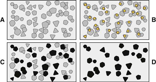
Following exposure, each grain of silver halide in film emulsion (Fig. 5-14, A) contains neutral silver atoms at their latent image sites (Fig. 5-14, B). These latent image sites render the crystals sensitive to development and image formation. Developer converts silver bromide crystals with neutral silver atoms deposited at the latent image sites into black, solid silver metallic grains (Fig. 5-14, C). These solid silver grains block light from a viewbox. Fixer removes unexposed, undeveloped silver bromide crystals (crystals without latent image sites), leaving the film clear in unexposed areas (Fig. 5-14, D). Thus the radiographic image is composed of light (radiopaque) areas, where few photons reached the film, and dark (radiolucent) areas of the film that were struck by many photons.
Developing Solution
The developer reduces all silver ions in the exposed crystals of silver halide (crystals with a latent image) to metallic silver grains (see Fig. 5-14). To produce a diagnostic image, this reduction process must be restricted to crystals containing latent image sites; to accomplish this, the reducing agents used as developers are catalyzed by the neutral silver atoms at the latent image sites (see Fig. 5-14, B). Individual crystals are developed completely or not at all during the recommended developing times (see Fig. 5-14, C). Variations in density on the processed radiographs are the result of different ratios of developed (exposed) and undeveloped (unexposed) crystals. Areas with many exposed crystals are darker because of their higher concentration of black metallic silver grains after development.
When an exposed film is developed, the developer initially has no visible effect (Fig. 5-15). After this initial phase, the density increases, rapidly at first and then more slowly. Eventually, all the exposed crystals develop (are converted to black metallic silver), and the developing agent starts to reduce the unexposed crystals. The development of/>
Stay updated, free dental videos. Join our Telegram channel
VIDEdental - Online dental courses


