19
Transversal Problems: Symmetric and Asymmetric Expansion
It is commonly accepted that, in the transverse dimension, normal occlusion is when the palatine cusps of the upper molars and premolars occlude in the fossa of lower molars and premolars.
This is also related to arch expansion, which is mostly defined by the patient’s skeletal condition, and is one of the key factors in success with aligners, as it is possible to expand asymmetrically with the archform tool – something that has been never possible with standard preformed NiTi archwires.

Fig. 19.1 Classic NiTi archwires were only available on standard sizes and shapes, now, with aligners, we can define exactly the best archform for every patient.
This is especially important in order to avoid gingival recessions associated with excessive dental expansions, and this is the reason why it is so important to use the archform tool to decide whether to have a regular expansion or more posterior/anterior sector one.

Fig. 19.2 Expansion can be defined in a precise way, with the decision about whether if it is more or less on anterior/posterior made according to patient’s available bone.

Fig. 19.3 Expansion with aligners can be defined in between Fa point (blue line) and Wa point (yellow line).
That said, a crossbite is a commonly seen discrepancy in the buccolingual relationship of the upper and lower teeth, when the lower teeth are in a buccal or labial position with regard the upper teeth, in a unilateral, bilateral, anterior and/or posterior manner.

Fig. 19.4 Dentoalveolar expansion can be achieved with aligners, as with braces and wires, to solve crossbites.
Crossbite malocclusion can have a skeletal or dental component or a combination of both. For this reason, when facing transversal problems, the first thing needed is a careful diagnosis, in order to determine the protocol to follow:
- Checking the occlusal view with the occlusal grid if there is a symmetric arch in shape, torque and size.
- In the frontal view, check the posterior lateral torques to see if torque in both sides is symmetric or asymmetric.

Fig. 19.5 In this situation, if we ask for the same amount of expansion in both sides, the left side with correct torque at the beginning will end up with premolars and molars tipped to labial and the labial cusp of those teeth would rise altering the Wilson curve.
- Smile analysis: check if the patient displays more gum on one side than on the other. Normally, if there is a side with less torque it will be accompanied by an increase in gum exposure on the same side.

Fig. 19.6 Check smile In unilateral masticatory side the patient will expose more gummy posterior smile in the non‐masticatory side. We will need to achieve a final alternate bilateral mastication and to make the torque of posterior teeth equal at the end of the treatment.
- For symmetric expansion ask for labial crown torque to the laterals, canines, premolars and molars until they become perpendicular to the bone (0 degrees of final torque).

Fig. 19.7 Asymmetric expansion.
- For asymmetric expansion: teeth on the side with correct torque in the posterior area should not be moved until correcting the side with altered torque. In this way, one hemiarch is being used as an anchorage to correct the other.

Fig. 19.8 Blue arrows indicate proper posterior torque, white ones show arch to be developed transversally.
- If patients need asymmetric expansions they should be informed that a final open bite in the posterior zone will require using intermaxillary elastics to close it.
- Protrusion: in patients with upper protrusion, in order to get a bigger expansion, the clinician should request the technician to apply a simultaneous movement of expansion and arch length reduction. In that way, retracting the incisors at the same time as expanding will provide us with very predictable and very effective transversal development of the arches.
19.1 Things to Consider in Expansion Cases
- Plan ahead for anchorage attachments to provide labial root torque to the premolars and molars during the expansion. AT HBG bevelled attachment to gingival of 4 mm in first premolars and first molars provide an effective anchorage during the expansion.
- Maintain third upper molars if possible and do not move them during the expansion.
- If second and third molars are not in posterior crossbite, for better posterior anchorage, do not move them during the expansion.
- Soften the contact points with metal strips if posterior contact points are tightened before the expansion.
- Consider how much overjet there is before doing the expansion: if there is not enough overjet, the moment the expansion is made, even if we do not see the retraction in the ClinCheck, the incisors will move backward (pearl necklace effect).

Fig. 19.9 Pearl necklace effect.
- For staging:
- Define staging
- Expansion and rotation corrections: move simultaneously
- Symmetric expansion: move simultaneously both sides
- Asymmetric expansion: sequential movement, first the side with negative torque or posterior crossbite and then the anchorage side.
- In the posterior view check in the final position of the ClinCheck that the palatal upper cusp of the molars occludes in the fossae of the lower molars.
The key to effective transversal development of the arches is the staging of movements:
- Symmetric expansion and provide a parabolic arch: this movement can be done simultaneously to
- Incisor retrusion (arch length reduction)
- Rotation of molars and premolars
- Minor corrections of molars through distalization
- Proclination
- Vertical goals: extrusion or intrusion of incisors.
If we need to expand and distalize , we can make at the same time the expansion, the mesial‐out rotation of first molars and the sequential distalization.
If we need to expand and procline: first expand (transversal compensation), second procline (sagittal compensation) and third, intrude or extrude (vertical compensation).
- Attachments: in the asymmetric expansion the key attachments are on the anchorage side, which is the side that is not going to move until the posterior crossbite on the contralateral side is corrected.
- In the anchorage side ask for rectangular attachments of 4 mm in first premolars and molars.
- In the side with negative torque or with posterior crossbite ask for horizontal attachments bevelled to gingival that provide a labial root torque to the root during the expansion.

Fig. 19.10 Smile picture.
19.2 Symmetric Expansion
19.2.1 Symmetric Compression Causing Anterior Open Bite

Fig. 19.11 Symmetric compression causing anterior open bite.
Diagnosis
A 26‐year‐old woman with a normodivergent skeletal class I presented with narrow arches and symmetric compression. She had a class I relationship with negative torque of posterior canines, premolars and molars, wisdom teeth erupted, labially flared maxillary lateral incisors and mild lower crowding, with a posterior gummy smile resulting from the inadequate posterior torque.
Treatment Plan
- Open space by upper expansion and sequential distalization
- In the lower arch, as the initial dental relationship was a class I, a sequential lower distalization was also planned
- All four wisdom teeth were extracted 2 weeks before the treatment start
Requirements for the Technician
- In the upper arch, make a symmetric expansion by changing torque applying labial crown torque to canines and premolars simultaneously to the sequential upper distalization of 1.5 mm.
- Sequence the movement on the incisors, first proclining 11 and 21 to make torque equal to 12 and 22 and to make space for the correction of the upper lateral and then making an IPR and applying a simultaneous movement of distal‐tipping of the crown in 12 and 22 and retrusion (relative extrusion). Horizontal attachments to be placed on the lateral incisors for better control.
- In the lower arch, make a sequential distalization, maintaining the class I molar relationship during the treatment.
Treatment Summary
- The total treatment was 18 months.
- The patient wore a set of 38 aligners used in a 10‐day change interval protocol.
- An additional aligners set was planned to settle the posterior occlusion.
- A final bilateral class I was obtained with adequate overbite and overjet, after uprighting posterior teeth, which provided the patient with a final beautiful smile and a stable occlusion.

Fig. 19.12 Pretreatment extraoral and intraoral views.

Fig. 19.13 Initial panoramic X‐ray, teleradiograph and cephalometry.

Fig. 19.14 Interproximal reduction.

Fig. 19.15 Upper superposition.

Fig. 19.16 Lower superposition.

Fig. 19.17 Initial right ClinCheck view, with CAD designer instructions.

Fig. 19.18 Initial left ClinCheck view, with CAD designer instructions.

Fig. 19.19 Comparison of initial and final occlusion.

Fig. 19.20 Comparison of initial and final occlusal.

Fig. 19.21 Comparison of initial and final smile overjets.

Fig. 19.22 Comparison of initial and final smiles.

Fig. 19.23 Final panoramic X‐ray and teleradiograph.
19.2.2 Symmetric Compression with Edge to Edge Bite

Fig. 19.24 Edge to edge bite with open bite tendency.
Diagnosis
A 33‐year‐old man with skeletal class I presented with narrow arches and symmetric compression. He had class I relationship with negative torque of posterior canines, premolars and molars, short display causing ‘old’ smile and edge‐to‐edge biteresulting from an upper laterals Bolton discrepancy.
Treatment Plan
- Space opening by upper expansion.
- Anchorage based on wisdom teeth.
- Anterior lower IPR to avoid black triangles and create overjet despite the Bolton discrepancy.
- All four wisdom teeth to be extracted 2 weeks before the start of treatment.
ClinCheck 1: Requirements for the Technician
- In the upper arch: make an incisors extrusion with optimized extrusion attachments on 12‐22 after torque correction
- In the lower arch: make a bilateral expansion with anterior lower IPR, adding lingual root torque to 32–42 to create an ‘en masse’ movement after space closure. IPR to be done after proclination to create good position for incisors to have the IPR done
This, so‐called ‘round tripping’ in the lower arch is usually avoided, but was considered to be more appropriate as the number of aligners would remain low. This is what we have done in the past with brackets and wires, after the first round NiTi aligned every teeth, so we consider it is not to be forbidden but to be avoided whenever possible. This allowed creation of both overjet with retrusion and overbite as aresult of relative extrusion.
Treatment Summary
- The total treatment was 17 months
- We planned two sets of aligners
- We obtained a final bilateral class I with adequate overbite and overjet, improving display to create a more aesthetic smile

Fig. 19.25 Pretreatment intraoral views (right, front, left, upper, lower).

Fig. 19.26 Initial extraoral view: short display.

Fig. 19.27 Pretreatment panoramic and lateral X‐rays.

Fig. 19.28 Pretreatment ClinChecks (right, front, left, upper, lower).

Fig. 19.29 Refinement intraoral views (right, front, left, upper, lower).

Fig. 19.30 Refinement smile.
ClinCheck 2: Requirements for the Technician
- In the upper arch: anterior torque 12–22 and alignment to create overjet and avoid anterior interferences
- In the lower arch: extra IPR added distal to canines to improve occlusion and slightly expanded posterior sectors to lose arch depth in order to increase overjet

Fig. 19.31 Refinement ClinChecks (right, front, left, upper, lower).

Fig. 19.32 Final intraoral views (right, front, left, upper, lower).

Fig. 19.33 Final smile picture and lateral X-ray.
19.2.3 Symmetric Compression Combined with Skeletal Class III

Fig. 19.34 Symmetric compression.
Diagnosis
A 42‐year‐old patient with hyperdivergent skeletal class III presented a with symmetric compression. He had a posterior gummy smile caused by posterior negative torque, upper midline cantered, mild lower crowding with prominent nasolabial folds, a prognathic profile and an opened nasolabial angle.
Treatment Plan
- Plan consisted of upper symmetric expansion, but as there was not enough overjet and the patient presented with lower crowding, we needed to distalize the lower arch in order to provide positive overjet before the upper expansion
- The patient did not want extraction of the lower third molar on the left side so IPR was planned in that quadrant and the space used to distalize lower teeth
Requirements for the Technician
- In the upper arch make a symmetric expansion and do not move the second and third upper molars to have posterior anchorage. AT horizontal bevelled to gingival used to provide labial root torque to the lateral segment during the expansion
- In the lower arch, make IPR to solve the crowding and to apply lingual root torque to the lower incisors
- Class III elastic to be used after uprighting the lower incisors
Treatment Summary
- The total time of treatment was 26 months
- The patient used a first set of 33 aligners in a 2‐week change interval protocol, and needed a new set of additional aligners to provide more overjet
- At the end of the first phase even though we asked for retraction of the lower incisors the overjet was not enough and the patient presented with premature anterior contacts and a posterior open bite
- To settle the occlusion in the additional aligners, we had to request further labial crown torque to the upper incisors and more IPR and retrusion of the lower incisors
- At the end of the treatment, the patient achieved a bilateral class I relationship with normal overbite and overjet and a smile improved considerably as a result of the arch expansions
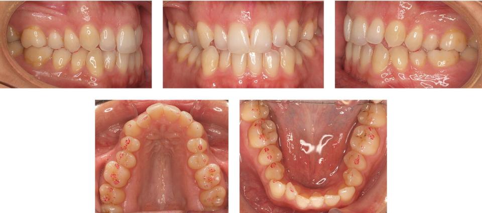
Fig. 19.35 Pretreatment intraoral views (right, front, left, upper, lower).

Fig. 19.36 Pretreatment panoramic X‐ray, teleradiograph and cephalometry.

Fig. 19.37 Upper CC superimposition and instructions to CAD designer.

Fig. 19.38 Lower CC superimposition and instructions to CAD designer.

Fig. 19.39 Attachments and IPR can be seen in several areas of the ClinCheck software.

Fig. 19.40 Right ClinCheck view, initial situation.

Fig. 19.41 Left
Stay updated, free dental videos. Join our Telegram channel
VIDEdental - Online dental courses


