Chapter III
The Complete Porcelain Veneer Crown
There is no more rewarding experience in dental technology than to construct a porcelain jacket crown which fits the die with almost the accuracy of a gold casting. In addition, to reproduce the colour, form and translucency of a human tooth to perfection is an equally challenging experience. Unfortunately, there are many teaching schools today who have eliminated the porcelain jacket crown from their curriculum and there are dental laboratories who only construct metal-ceramic crowns. This has resulted in many students growing up without seeing the high aesthetic standards set by the porcelain jacket crown. It is very easy to become accustomed to a “Metal-Ceramic Smile” and unless we are prepared to look at anterior tooth aesthetics more critically, there is every chance of a continuing deterioration in the student’s appreciation of what constitutes near-perfection. It is also to be regretted that many ceramists have now lost the facility for laying down a platinum matrix, a simple operation, which can be done by trained apprentices in a matter of minutes. It is therefore appropriate to consider the forming of the platinum matrix as the basis of all good porcelain veneer crown work. An accurate porcelain butt fit is the only answer to the patient’s desire for teeth that look as if they “grow out of the gum” (Fig. 3-1). A full understanding of the art of making porcelain jacket crowns will automatically improve the ceramist’s skill when constructing metal-ceramic crowns.
Reproducing Tooth Anatomy in Dental Porcelain
It is essential that the dental ceramist has a detailed knowledge of dental anatomy. To achieve this he must continually examine human teeth, read textbooks of dental anatomy (Wheeler, 1969; Gründler, 1976) and familiarise himself with the outline form, occlusal tables and surface characteristics of every tooth in the dental arch.
The most important feature to recognise in tooth anatomy is that every tooth is formed by the combination of four or more lobes. Each lobe represents a primary centre of formation. As Wheeler (1969) states, “the multiplication and fusion of lobes during tooth development are demonstrated graphically when teeth are viewed from the mesial or distal aspects.” All anterior teeth show traces of four lobes, three labially and one lingually, the lingual lobe being represented by the cingulum (Fig. 3-2). Each labial lobe of the incisor terminates incisally in rounded eminences known as mamelons. The junction between the three lobes in the incisors account for the labial grooves which are clearly seen in most teeth. In the case of the premolars and molars the lobes correspond with a cusp (Fig. 3-3). When building the veneer porcelains the ceramist should observe this lobe formation and place his porcelain accordingly.
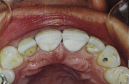
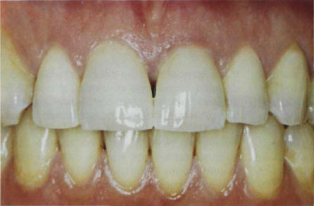
Figure 3-1b
Fig. 3-1a and b Aluminous porcelain veneer crowns with high alumina bite-pad inserted on 11, 21. (a) Palatal view. (b) Facial view.
Another important aspect of tooth anatomy is the geometric form of crown outlines. This may be summarised as follows:
| Facial and lingual aspects |
– trapezoidal (Fig. 3-4) |
| Mesial and distal aspects of anterior teeth |
– triangular (Fig. 3-5) |
| Mesial and distal aspects of maxillary posterior teeth |
– trapezoidal (Fig. 3-6) |
| Mesial and distal aspects of mandibular posterior teeth |
– rhomboidal (Fig. 3-7) |
In addition, the outline form of the occlusal tables is equally important. The maxillary molars are nearly always rhomboidal in form whereas the mandibular molars are trapezoidal.
Failure to recognise these main anatomical features in teeth will result in the production of ceramic work which is flat and uninteresting. To capture the beauty of natural teeth, the ceramist must build each lobe or cusp individually. Even when building an upper incisor he must still duplicate the undulating form of the labial surfaces produced by the fusion of the three facial lobes. Natural teeth in the unworn state are rounded in form. It is only during masticatory wear that sharp line angles are created.
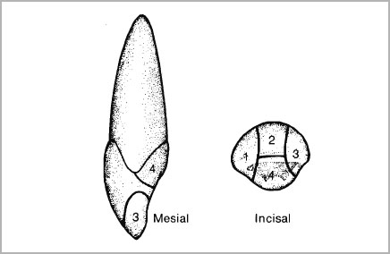
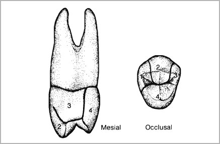
Fig. 3-3 Maxillary premolar showing the four lobes from which the cusps develop.
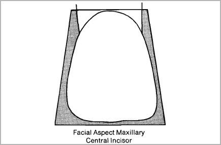
Fig. 3-4 Facial aspect of maxillary incisor showing its trapezoidal form.
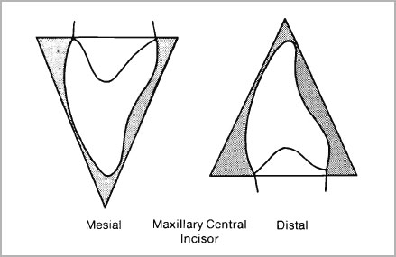
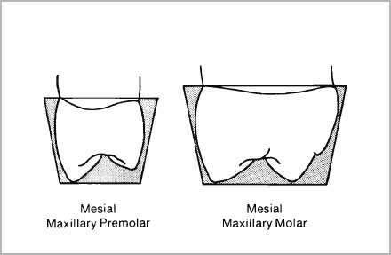
Fig. 3-6 Mesial aspect of maxillary premolar and molar showing their trapezoidal form.
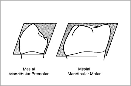
Fig. 3-7 Mesial aspect of mandibular premolar and molar showing their rhomboidal form.
Construction and Shade Matching
Ideally, the ceramist should fabricate a custom-built shade guide of aluminous porcelain jacket crowns and use these in conjunction with shade buttons as described in Monograph III of this series (McLean, 1979). Such a procedure is suited to the individual dentist or technician. However, the large laboratory-owner is generally presented with a specific shade, selected by the dentist from a modern multi-blended vacuum-fired tooth shade guide. The aluminous porcelains were formulated with this situation in mind and a knowledge of how a vacuum-fired shade guide tooth is blended is vital to the technician.
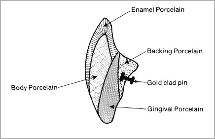
An examination of a modern multi-blended vacuum-fired denture tooth reveals that it comprises four basic colours (Fig. 3-8). These colours consist of a backing porcelain containing the pin anchorage, a darker dentine colour that is carried up into the gingival of the tooth to create a dense root area, and the body or dentine porcelain overlaid by a translucent enamel. This enamel usually covers the labial and palatal aspects of the incisal edge and overlaps the dentine on the entire labial surface (Fig. 3-8). Various concentrated body and surface stains are applied as effect masses.
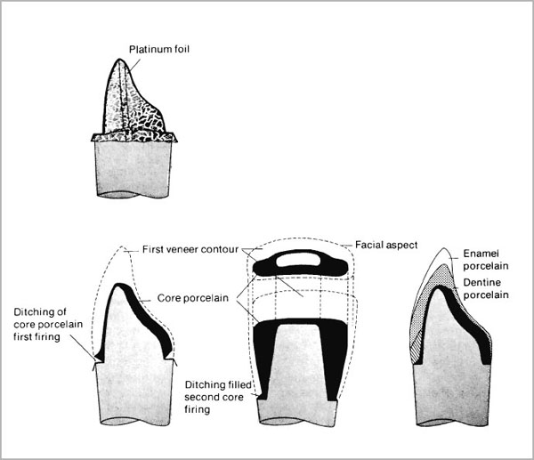
In order to duplicate a vacuum-fired shade guide tooth, the aluminous porcelain must be fired in layers corresponding to the layers of the shade guide tooth enamels and dentines. The core porcelain will correspond to the dense backing porcelain containing the pin anchorage and the gingival porcelain (a darker dentine colour) should be chamfered and overlaid with the main body dentine. The enamel overlaps the entire structure and will give depth of translucency to the finished crowns. It will be seen that the secret of success is to build the porcelain in layers with all the colour built-in to give a three-dimensional effect (Fig. 3-9).
In order to illustrate the aluminous porcelain system, the technique for building a Vitadur crown, matching a Vita A2 vacuum-fired shade guide tooth using Vitadur N aluminous core porcelain and Vitadur N enamels will be described.
Although many attempts have been made to replace platinum foil in jacket crown construction, alternative metals such as palladium have never become popular. Platinum is a unique metal; the high melting temperature of 1769°C makes it particularly suitable for use with porcelain since a thin foil is very susceptible to metal creep or even melting during the firing of porcelain. In addition, platinum can be very easily burnished in the dead soft condition.
When adapting a platinum foil matrix to a die, the important points to observe are:
- Make certain there is sufficient platinum to cover the die, leaving a skirt and providing thickness for a tinner’s joint.
- Never allow the foil to crease. Keep it pulled tightly around the die during all the forming operations.
- Do not hurry; make certain that each step is accurately done before proceeding with the next one.
- Do not over-trim the tinner’s joint area, but if it is more than 1 mm wide before folding over the platinum, the joint will be weak and can open during fabrication.
- Do not use heavy pressure when burnishing.
- Anneal platinum immediately it work hardens.
The decision where to place the tinner’s joint can be controversial. Derand (1974) has shown that the maximum tensile stresses occurring during function are in the approximal regions of a jacket crown. Therefore it is important not to weaken this area by an excessive thickness of platinum. However, by placing the tinner’s joint on the lingual surface of the tooth, it is possible to reduce the thickness of the lingual plate of porcelain and introduce a cleavage line. In the average case in our laboratory we use the approximal tinner’s joint.
Armamentarium:
Fine pointed scissors
Pointed tweezers (straight or angled)
Beaver tail burnisher (Ash No. 5)
Scalpel-holder and blades
Orange wood sticks
Swager (optional)
Construction Using Approximal Tinner’s Joint
- Lay the die on its side on a piece of paper. Pull the paper around the die and grip it firmly in the fingers (Fig. 3-10a). Cut the paper to allow for a 3 mm excess at tinner’s joint on the incisal and approximal margins. Trim the paper at the cervical margin and allow for a 3 mm extension for the platinum skirt.
- Lay the paper over the foil and score a line around the edge. Cut the foil around the score line (Fig. 3-10b).
- Lay the die on its side against the foil and hold it firmly in position with the index finger. Smooth the foil around the die with the fingers (Fig. 3-11) and with the other hand pull it tightly to position on the opposite side. If the technician keeps pulling and smoothing the foil, it is possible to wrap it round the preparation and secure very tight and smooth adaptation with hardly any burnishing with instruments (Fig. 3-12a and b). This is the most important step in the operation. Do not allow the foil to become creased and do not attempt to burnish it into the shoulder.
- Squeeze the foil tightly along the axial wall and incisal edge with a pair of pointed tweezers until the preparation is clearly outlined (Fig. 3-13a and b). At this stage smooth the foil around the preparation with the fingers and again squeeze the edges with the tweezers.
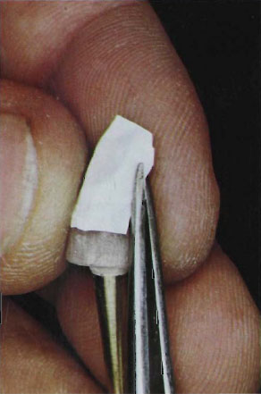
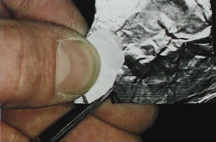
Figure 3-10b
Fig. 3-10a and b (a) Making paper pattern for platinum matrix. (b) Platinum foil cut out from paper pattern.
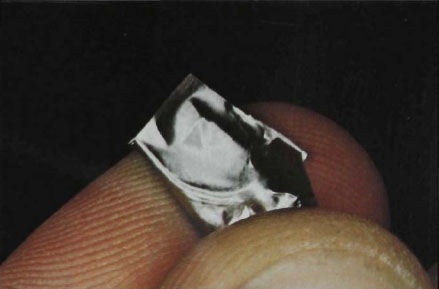
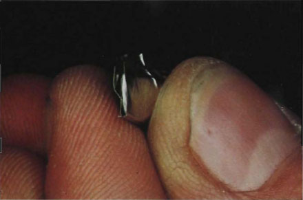
Figure 3-12a
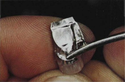
Figure 3-12b
Fig. 3-12a and b (a) Foil adapted tightly around the die. (b) Lightly burnishing margin. Do not burnish into the axial wall line angle.
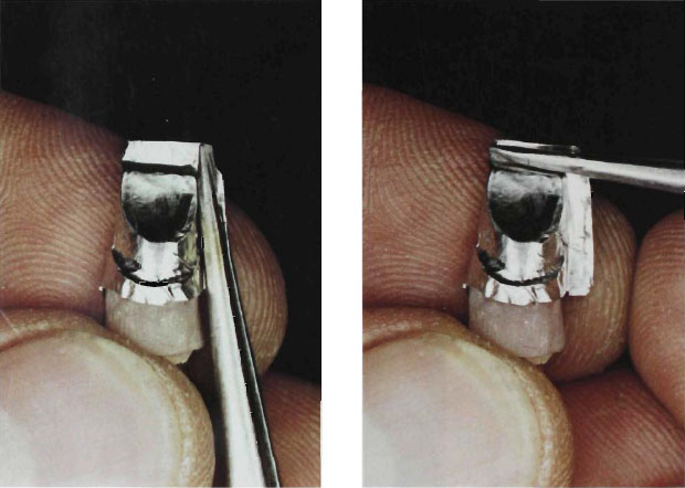
5. Trim the foil at the incisal and approximal edges with a pair of sharp scissors so as to leave an excess of 1.5 mm of platinum (Fig. 3-14). Do not over-trim; if the joint area is left short there will be no chance of forming a tight and permanent tinner’s joint.
6. Open up the approximal joint very carefully and insert the tip of the scissors inside. Cut a small sliver of platinum from the lingual flap area so that about 0.75 mm of platinum is left protruding (Fig. 3-15). Repeat this operation at the incisal joint area.
7. Trim the foil at the axio-incisal corners so as to allow the maximum width of incisal joint. The angle of cut will vary with the width of preparation, very small incisors requiring almost a 90° angle. The approximal joint should be cut in a similar fashion (Fig. 3-16a and b). In order to reduce the thickness of the joint at the cervical margin, it can be advantageous to cut a small “V” exactly at the margin so that the joint can be folded in, thereby avoiding a thick edge (Fig. 3-17a and b).
8. Grip the labial portion of the approximal foil in the tweezers and fold it over the shorter lingual foil (Fig. 3-18). Make sure that the fold is exactly at the free edge of the lingual foil. Squeeze the three layers of platinum foil tightly together. The approximal tinner’s joint is now complete and should be 0.75 mm wide.
9. Repeat the tinner’s joint operation at the incisal fold and make certain that the joint is placed lingually (Fig. 3-19a and b). Burnish the tinner’s joint tightly to the die with a beaver-tail burnisher and gradually work down the matrix in a circular movement until the foil is closely adapted to the axial walls. Any excess foil should be pushed down towards the shoulder. Once this is complete, use an orange wood stick or beaver-tail burnisher to burnish the platinum into the axio-gingival line angles (Fig. 3-20a and b). There should be no tearing of the foil providing all burnishing is directed from the incisal in the early stages and then towards the approximal joint. In this way all the excess is moved towards the joint area which can give.
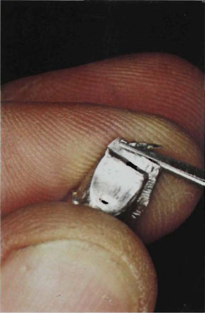
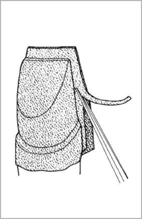
Figure 3-15a (left)
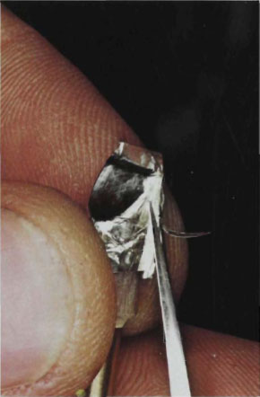
Figure 3-15b (right)
Fig. 3-15a and b (a) Diagram of the correct cut for the lingual flap area. (b) Lingual flap area cut back by 0.75 mm ready for forming the tinner’s joint.
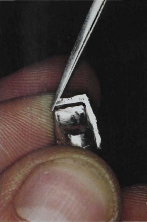
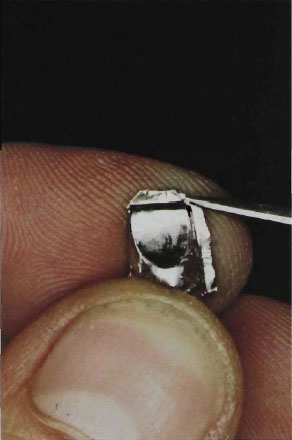
Figure 3-16b (right)
Fig. 3-16a and b Cutting the axio-incisal corners to allow maximum width of incisal joint; (a) mesial cut (b) distal cut.
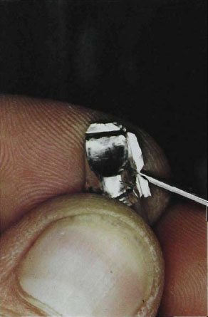
Figure 3-17a
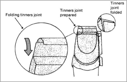
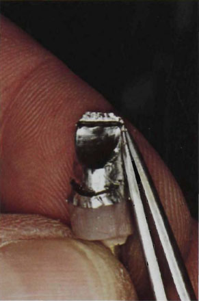
Fig. 3-18 Forming the tinner’s joint at approximal area.
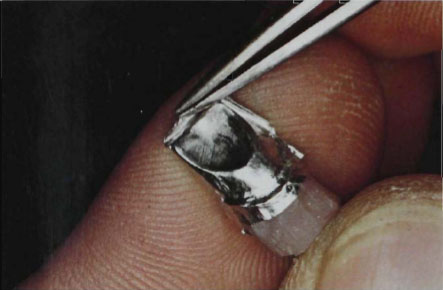
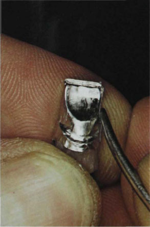
Figure 3-19b
Fig. 3-19a and b (a) First fold of incisal tinner’s joint. (b) completing the tinner’s joint.
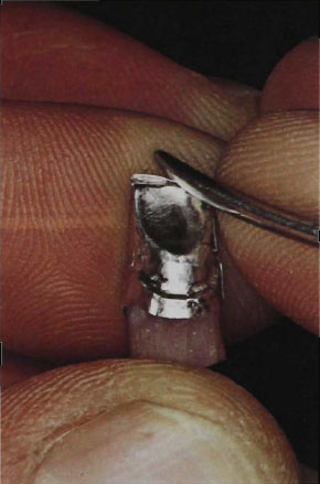
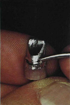
Figure 3-20b (right)
Fig. 3-20a and b Completion of burnishing of the foil working from (a) incisal to (b) the cervical.
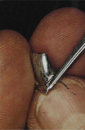
Fig. 3-21 Trimming platinum foil skirt to leave an extension of 11/2 mm.
10. Before trimming the foil at the skirt and finally burnishing the shoulder area, make sure that it is lifting off cleanly from the die. If the foil matrix sticks to the die it may be easily removed by attaching it to a small piece of sticky wax. Only then should the skirt be trimmed to leave approximately 1.5 mm of platinum (Fig. 3-21). Replace the foil on the die and reburnish.
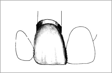
Building the Core Porcelain for a Maxillary Central Incisor
The aluminous core porcelains provide the main reinforcement in the porcelain crown and they must be placed correctly if high strength is to be combined with aesthetics. The core should extend beyond the preparation in the approximal areas and cover the entire lingual surface to a depth of a least 1 mm. The labial surface should be as thin as possible in the incisal third and must not extend beyond the incisal edge of preparation. As the core porcelain extends towards the shoulder it may be chamfered to a knife-edge as it meets the external cervical margin (Fig. 3-22). The approximal core porcelain should be placed as far lingually as possible, leaving plenty of room for enamel porcelain. The core porcelain will then act as a strong reinforcing plate on the lingual. Common faults in laying down core porcelain are extending it beyond the incisal edge or thickening of the labial surface. Incorrect placement of the core will reduce the enamel veneer thickness and the opaque core may then shine through the surface (Fig. 3-23). The aluminous core porcelain should act as a light diffusion zone which provides a neutral background for the enamel and dentine porcelains but at the same time masks the cement lute. Building the labial core porcelain too thickly will completely defeat the action of this colour filtration, turning the core porcelain into a classical opaque layer which is highly light reflective.
Building the core porcelain too thinly on the lingual is also another major fault since all the reinforcing effects of the aluminous porcelains will be lost (Fig. 3-24).
Aluminous porcelains required for building a Vitadur N crown Shade A2:
| Core porcelain | Vitadur N 338 |
| Gingival porcelain (A3) | Vitadur N 353 |
| Dentine porcelain | Vitadur N 352 |
| Enamel porcelain | Vitadur N 347 |
Mix the Vitadur N core porcelain with the P-liquid on a glass slab. The mix should form a thick slurry of creamy consistency. Clean a No. 6 Rowney sable brush in distilled water and absorb the excess moisture on the sponge contained in the stainless steel dish. The tip of the brush should now have a fine point. Push the point of the brush into the edge of the porcelain mix and pick up a bead of porcelain. Transfer the bead to the platinum matrix and start to coat it from the labial surface (Fig. 3-25a). A gentle pushing and tapping motion will allow the porcelain to wet out the surface. Continue to lay on further increments of porcelain until the entire matrix is lightly coated with a thin film. Vibrate the die with the serrated end of a Le Cron carver and dry off the surface with a paper tissue (Fig. 3-25 b). Thorough vibration of the core porcelain is strongly recommended since the greater the density of aluminous core porcelain, the higher the fired strength will be. This is in contrast to the veneer porcelains where heavy vibration can cause slumping of colours.
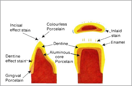
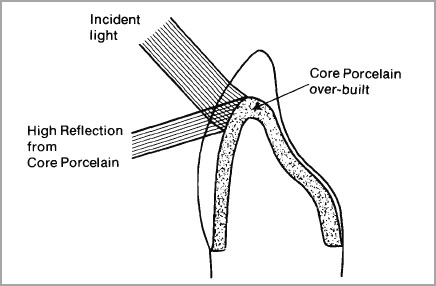
Fig. 3-23 Incorrect placement of aluminous core porcelain causing high light reflectivity through the enamel veneer.
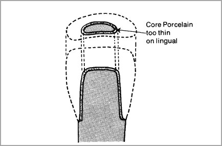
Fig. 3-24 Aluminous porcelain core built too thin on the lingual to achieve proper reinforcement.
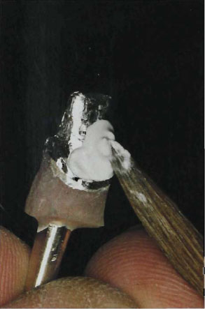
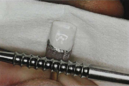
Figure 3-25b
Fig. 3-25a and b (a) Transferring bead of core porcelain to platinum matrix. (b) Vibrating core porcelain with serrated end of Le Cron carrer.
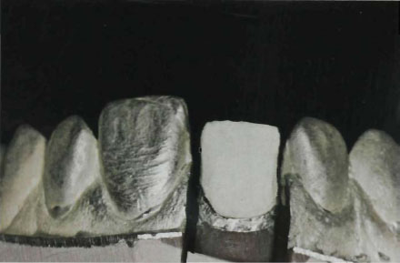
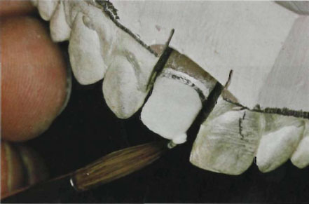
Fig. 3-27 Completion of aluminous core build-up which is extended into the approximal areas and thickened on the lingual.
On completion of the initial coating of aluminous core porcelain the platinum matrix should just be influencing the colour of the labial core porcelain (Fig. 3-26). This will ensure that the fired core porcelain will not affect aesthetics by shining through the enamel veneers. At this stage make certain that the aluminous core porcelain on the slab is not drying out; if so, re-moisten it. Now proceed to build up the lingual surface to full contour (ca. 1 mm) and add more core porcelain to the approximal surface to extend it like two wings (Fig. 3-27). Vibrate and condense thoroughly, holding the paper tissue on the labial surface to absorb moisture and prevent slumping. Remove any excess porcelain from the skirt and replace the die and porcelain build-up on the cast. Check that the structural design is correct (Fig. 3-22).
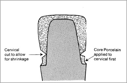
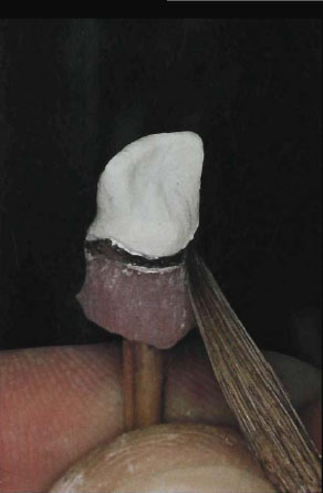
Fig. 3-29 Aluminous core porcelain removed from cervical margin. Cervical ditching technique.
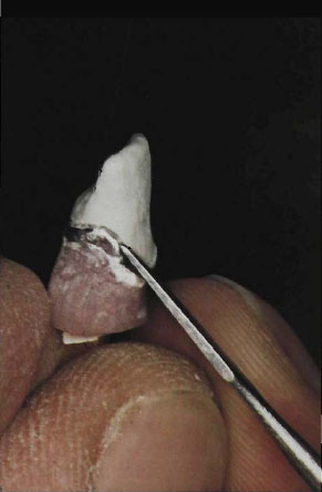
Fig. 3-30 Reburnishing of the platinum skirt after first firing.
- Thin labial and incisal coverage.
- Full lingual coverage but not altering incisal guidance.
- Small extension wings in the approximal zones for strength.
- Neat finishing lines at the cervical.
The shrinkage of porcelain makes it difficult to achieve an accurate fit of the core porcelain in one bake. It is therefore very important to allow for this shrinkage and prevent the fired porcelain from lifting the platinum skirt and spoiling the fit. Two ways have been advocated:
- The cervical contact technique.
- The cervical ditching technique.
The cervical contact technique relies on the application of a layer of porcelain around the shoulder area to shrink first. The second bake will then shrink towards the cervical porcelain and maintain the fit (Fig. 3-28). The cervical contact technique does not always work since the bulk of the core porcelain still has to shrink during the second bake. It is for this reason that the cervical ditching technique is strongly recommended. Here the porcelain is removed from the shoulder area after the initial build-up is complete. The No. 6 Rowney brush or a fine-bladed instrument will do this effectively. The art is to make the thinnest ditch possible and just expose the cervical platinum at the shoulder (Fig. 3-29). The core porcelain is now ready for its first bake and is placed on a sagger. For purposes of illustration firing procedures in the Vita Vacuumat-S Furnace will be described.
Vitadur N Core Porcelain – First Firing
Drying
Muffle entrance 3 min
Apply vacuum with the temperature at 800°C
Firing
Enter hot zone of furnace
Raise temperature to 1100°C at 50°C per minute
Break vacuum at 1100°C and leave in furnace at 1100°C for 2 mins
Cooling
Cool at muffle entrance
Remove work and bench cool
Vitadur N Core Porcelain – Second Firing
After cooling, replace the core porcelain on the die and push it firmly to place. Re-burnish the platinum foil with a blunt Le Cron carver or orange wood stick at the skirt and make sure that it is tightly adapted to the internal axial walls. This is a very important operation and will determine the ultimate accuracy of fit (Fig. 3-30). Moisten the core porcelain with the brush and fill in the ditched area and any surface fissures with a slurry of Vitadur N core porcelain. Condense and remove excess from skirt very carefully. Meticulous attention to detail at this stage can be rewarded by a crown that can fit the tooth within 20 µm (McLean and Fraunhofer, 1971).
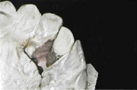
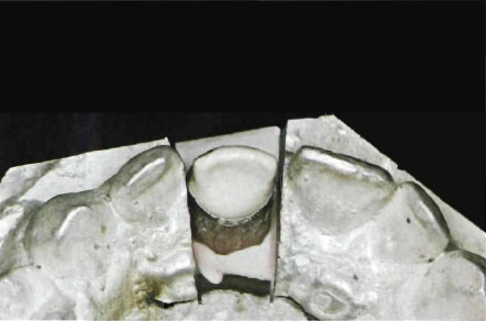
Figure 3-31b
Fig. 3-31a and b Completed core porcelain after second firing. (a) Lingual view. (b) Incisal view.
Vitadur N Core Porcelain – Second Firing
Drying
Muffle entrance 3 mins
Firing platform 3 mins
Do not apply vacuum
Firing
Enter hot zone of furnace at 1100°C
Hold in air at 1100°C for 10–15 mins
Cooling
Cool at muffle entrance
Remove work and bench cool
The finished core porcelain is shown in Fig. 3-31a and b. Note the clean finishing line and good fit of the fired porcelain. If the fit is established at this stage the core porcelain, unlike regular felspathic porcelain, will not distort during firing of the enamel veneers since the firing temperature of the Vitadur N porcelains is 150°C below that of the Vitadur N core porcelain.
Summary of the Firing Requirements for Core Porcelains
- Raise firing temperature slowly (50°C per minute). Rapid drying and firing increases the risk of fissuring in the core.
- Break vacuum immediately on reaching maximum maturing temperature. Continuous firing in vacuo will cause the glass to “bloat” and honeycomb porosity will develop.
- Air-fire for at least 15 minutes at maximum maturing temperature or even higher for extra strength. Heat soaking alumina crystal/glass composites improves density and bonding of crystals to the porcelain matrix and strength can be greatly increased (McLean, 1966; Jones et al., 1972).
- After cooling, check degree of fusion by immersing in ink or a water soluble dye. If surface is dense with no honeycomb porosity, the dye will wash off cleanly.
Application of Vitadur N gingival and Body Porcelains Shade Vita A2
Mix Vitadur N dentine porcelain No. 353 with distilled water on a glass slab to a creamy consistency. Moisten the core porcelain with distilled water and apply the neck porcelain No. 353 in small increments to the gingival area. Using the moist brush, smooth the porcelain towards the incisal area so that it is chamfered to a fine edge about one-third the distance from the cervical margin (Fig. 3-32). Make certain that the porcelain has a gradual chamfer since a sharp angle can create demarcation lines. Condense the porcelain by vibrating with the serrated end of a Le Cron carver and drying with a paper tissue.
Apply the body dentine porcelain No. 352 to the remaining core porcelain using the incremental brush technique described on page 48. Work the porcelain from the incisal edge first and carry it down the labial surface towards the gingival porcelain. In this way the body porcelain will blend easily with the slightly moist gingival porcelain. When building dentine porcelains make sure that the layer contacting the core or opaque porcelain is thoroughly condensed. Fill in any small fissures in the core porcelain with a thin slurry of dentine. Good wetting of the core porcelain will only be achieved if the porcelain is kept moist. Continue to build around the approximal areas, but do not fill in the approximal space at the gingival (Fig. 3-33). Always maintain the correct contour of the tooth and avoid slumping by keeping the paper tissue held behind the crown. Extend the porcelain incisally to a length of 1 mm to allow for shrinkage. Finally cover the lingual core porcelain and build up the dentine to the correct occlusal relationship (Fig. 3-34).
The building of the dentine porcelain is critical since its final anatomical form will determine not only the contour of the crown but also the blending of colour. Many students think that corrections can be made after firing, but once an incorrect layer has been formed, it is impossible to go back and alter it by grinding without contaminating the porcelain. Another misconception is that shrinkage will be so great that it does not matter too much if the build-up is slightly wrong. Again, this is a dangerous philosophy since an expert ceramist should be able to judge his shrinkage so accurately that surface corrections should only be made at the contact areas and perhaps a little at the incisal.
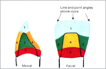
How does the beginner judge shrinkage? Porcelain will always shrink towards its greatest bulk and these areas are to be found at the incisal, the approximal and at the supra-bulge. The areas of greatest porcelain shrinkage are shown in Figure 3-35 and numbered in descending order. Area 1, the incisal, will have the greatest bulk of “green” porcelain during firing of an aluminous porcelain crown and will therefore have to be extended. Line and point angles delineate areas of bulk porcelain and shrink more. By contrast, area 4, the lingual and labial surfaces overlaying the core porcelain, will shrink least since the core porcelain will have already accounted for much of the shrinkage. It is therefore important for the ceramist not to over-build the labial and lingual surfaces. A fat crown in the “green” stage will still be a fat crown in the fired stage. The development of correct anatomy at the dentine build-up stage will always be rewarded in the fired stage. Slightly exaggerate line and point angles, and do not under-contour the supra-bulge of the tooth.
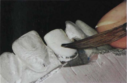
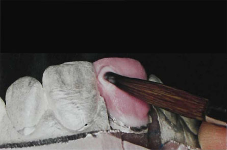
Fig. 3-33 Building approximal body dentine.
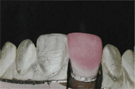
Fig. 3-34 Completed dentine porcelain build-up.
Application of Vitadur N Enamel Porcelain Shade Vita A2
Before mixing the enamel and translucent porcelains, make sure that the dentine build-up is kept moist.
Using a sharp knife (Sword porcelain carver)a cut back one half of the dentine porcelain to the blend line outlined in the shade prescription or corresponding to the shade guide tooth (Fig. 3-36a). Check that at least 0.5 mm of dentine porcelain is covering the core at the incisal with a periodontal probe (Fig. 3-36b). Remove the other half of the incisal dentine and smooth the surface with the No. 6 Rowney brush (Fig. 3-37a to c). Apply the Vitadur N enamel No. 347 to the surface, making sure that each increment is positioned very gently. Tapping it lightly to place will avoid disturbance of the underlying dentine porcelain. Keep the porcelain moist but it must not slump during application. Smooth the enamel porcelain down towards the dentine blend line (Fig. 3-38) and extend it approximally. Do not alter the original contour of the tooth. The finished enamel should be extended by 1 to 1.5 mm beyond the adjoining central incisor (Fig. 3-39). Thicker enamels reduce Value and increase translucency.
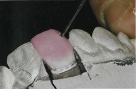
Figure 3-36a
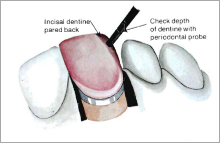
Figure 3-36b
Fig. 3-36a and b Paring back one half of the dentine for enamel blend line (a) and checking that incisal thickness is not less than 0.5 mm with a periodontal probe, (b) otherwise core porcelain may show through. Enamel blend lines will vary but it is important to remove some approximal dentine if a natural effect is to be obtained. The depth and length of cut will control the enamel thickness and therefore the value of the crown. Thicker enamels reduce value.
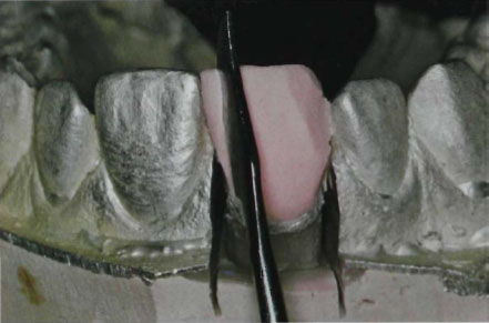
Figure 3-37a
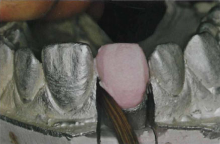
Figure 3-37b
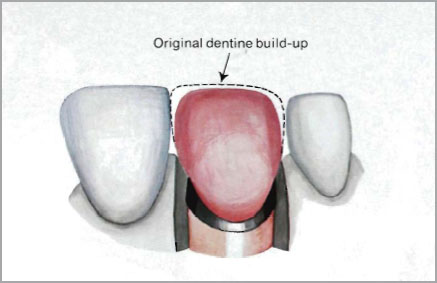
Figure 3-37c
Fig. 3-37a to c (a) Paring back mesial surfaces of dentine for enamel blend line. (b) enamel blend line smoothed with brush. (c) Diagram of enamel blend line.
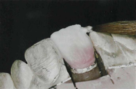
Fig. 3-38 Application of enamel porcelain.
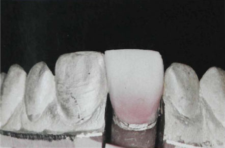
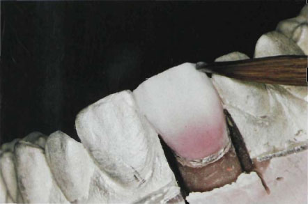
Figure 3-40a
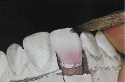
Figure 3-40b
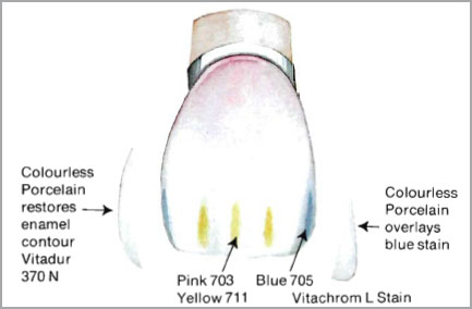
Figure 3-40c
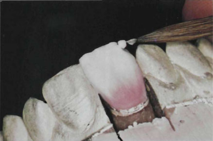
Figure 3-40d
Fig. 3-40a to d (a) Mesial and distal enamel corners pared away and a small quantity of blue stain applied. (b) Incisal area pared away for application of pink and yellow stain. (c) Diagram of areas of colour and stain application. Stain should be applied like the painting in the diagram to create a diffuse colour zone. (d) Facial stain areas covered with enamel and colourless porcelain.
The removal of the incisal dentine might be questioned. Why put it there in the first place if it is to be carved away later? The answer is that it gives the ceramist complete control of the length of the tooth. For example, when building multiple units, the adjoining teeth can act as guides and even in the case of the single tooth the beginner can chamfer the mesial half first and use the distal half of the incisal dentine as a control. The building of multiple units will be shown for the platinum bonded alumina crown.
Special Effects and Characterisation of the Enamel
Subtle use of inlaid colours, stains and translucent porcelains will often transform a porcelain crown that otherwise could look very artificial in the mouth. The development of these special effects is often needed when matching an adjoining tooth and is essential for light break-up when building multi-units. Details of characterising surface enamels and body dentines are given in Chapter VI. For this case Vitachrom L stains, blue (705) light pink (703) and light yellow (711) were used. Their method of application is illustrated in Figures 3-40a to d.
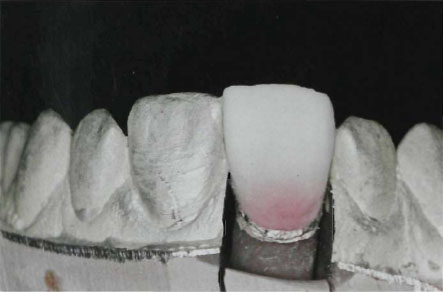
Figure 3-41a
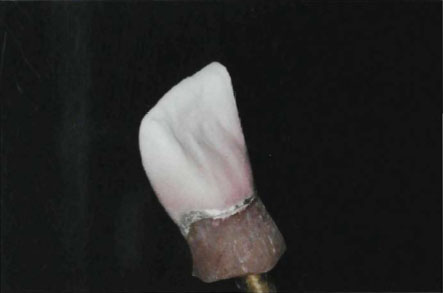
Figure 3-41b
Fig. 3-41a and b Completion of the building-in of the enamel colour. (a) Facial view. (b) Lingual view.
Surface Finishing of the “Green” Porcelain
On completion of the building-in of dentine colours and enamel characterisation, the porcelain build-up should be checked for detail (Fig. 3-41a and b). In the case of the maxillary central incisor just described, the following surface characteristics should be present, as shown on Figure 3-42a. Although the anatomical details can be refined after the final biscuit bake, the nearer to the glazed crown shown in Figure 3-42b that the “green” porcelain is built the better the final result.
Maxillary Central Incisor
- Crest of curvature mesially and distally should correspond with contact area of adjoining tooth.
- Mesial outline only slightly convex with the contact area approaching the mesioincisal angle.
- Distal outline more convex with a more rounded incisal angle.
- Incisal outline corresponding with adjoining tooth. Incisal ridge sloping towards lingual.
- Labial face broad and flat particularly at incisal third.
- Shallow concavity for lingual fossa with clearly defined cingulum.
- Mesial and distal marginal ridges. Maxillary Lateral Incisor
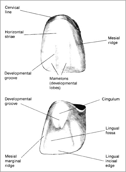
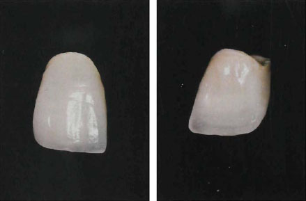
Figure 3-42b
Fig. 3-42a and b (a) Diagram of the important anatomical features in a maxillary central incisor tooth, (b) Completed maxillary central incisor porcelain crown.

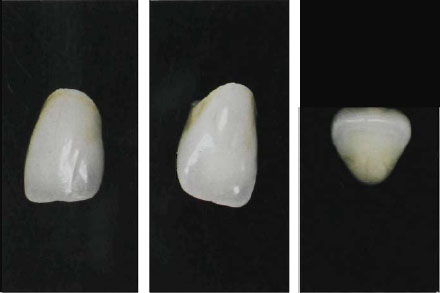
Figure 3-43b
Fig. 3-43a and b (a) Diagram of the important anatomical features in a maxillary lateral incisor tooth, (b) Completed maxillary lateral incisor porcelain crown.
Maxillary Lateral Incisor
These teeth can vary in development more than any other tooth in the mouth but there are certain anatomical features which, if omitted, can make the crown look very artificial. The essential features are illustrated in Figure 3-43a and b.
- Greater labial curvature than the maxillary central incisor.
- Crest of contour mesially is usually at the point of junction of the middle and incisal thirds.
- Distal outline more rounded than the mesial. Labial crest of contour lies more cervically than the central incisors.
- Mesial and distal marginal ridges are prominent with a distinctive cingulum.
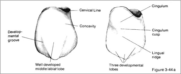
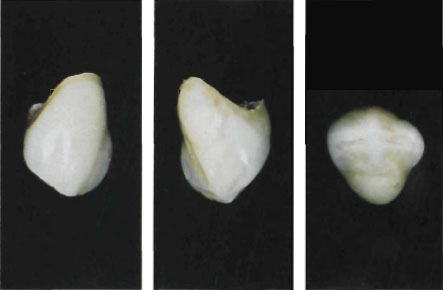
Figure 3-44b
Fig. 3-44a and b (a) Diagram of the important anatomical features in a maxillary canine tooth, (b) Completed maxillary canine crown.
The Maxillary Canine Tooth
Few teeth present a greater challenge to the ceramist than the maxillary canine since the labial face is very difficult to capture in porcelain. The details of the canine anatomy are shown in Figures 3-44a and b.
- Smooth labial surface except for shallow depression dividing the three developmental lobes.
- Central developmental lobe creating prominent labial ridge.
- Concavity distal to labial ridges.
- Large cingulum with heavy marginal ridges.
The anterior maxillary teeth are the most suitable for crowning with aluminous porcelain. Details of the anatomy of the mandibular teeth and maxillary posterior teeth will be given under sections dealing with the bonded alumina crown and the cast metal-ceramic crown.
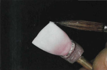
Figure 3-45a
Firing the Aluminous Veneer Porcelains Vitadur N
On completion of the veneer porcelain build-up and addition of excess porcelain to the contact areas (Fig. 3-45a and b) smooth the surface very gently with the large soft hair brush. Any coarse particles will be removed from the surface. Place the build-up on a sagger and the crown is ready for the first bake.
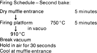
Recommended firing schedule:
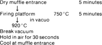
The best results are obtained when only one bake of porcelain is needed. However, only the very experienced technician can hope to achieve this and sometimes additions of veneer porcelain may be required at the incisal or contact areas. Clumsy addition of porcelain to the incisal edge can often ruin the appearance of a crown so that this area is one to treat very carefully. Minor corrections to the body dentine or approximal enamel can be made without spoiling the effect. Conversely, if these areas have been overbuilt, then grinding back could eliminate some of the built-in colour and also cause surface contamination of the porcelain. Before making any correction:
- Scrub the porcelain thoroughly.
- Ultrasonically clean in distilled water. Apply any additional porcelain to a moist surface and condense thoroughly.
Warning. Do not apply corrective porcelain to a glaze surface. Peeling of the glaze could then occur. In the ceramic industry there is an old saying: “Never put glaze upon glaze.”
If the surface on the crown shows signs of glazing it must be lightly ground with diamond stones and cleaned before adding more porcelain. Alternatively the surface can be lightly blasted with 30 µm Al2O3 grit.
The aluminous porcelain crown fired to the high biscuit stage and prior to contact area adjustment is illustrated in Figure 3-46. The crown will require further light grinding and finishing to achieve the final tooth form. The built-in colour and approximal translucency is already visible.
Armamentarium:
Stay updated, free dental videos. Join our Telegram channel
VIDEdental - Online dental courses


