Chapter VII
Construction of Metal-Ceramic Bridgework
- Tensile stress. The internal induced force that opposes elongation of a material in a direction parallel to the direction of the stress.
- Compressive stress. The internal induced force that opposes shortening of the material in a direction parallel to the direction of the stress.
- Shearing stress. The internal induced force that opposes the sliding of one plane of the material on the adjacent plane in a direction parallel to the stress.
Dental porcelain is weak in tension and shear but strong in compression. The design of a bridge should minimise or avoid tensile and shear Stresses developing at the metal-porcelain interface or within the porcelain veneer. The thickness of the porcelain veneer is very important and Craig et al. (1967) have drawn attention to the importance of the design of the metal substructure. The improvement of engineering designs is accomplished by two methods (1) the cross-sectional area of low stressed regions may be reduced and (2) the crosssectional area in the regions of maximum stress should be increased, allowing the concentration of stress to be distributed over a greater area.
The areas of greatest stress in a metal-ceramic fixed bridge are related to the direction of the forces of occlusion and the length of span of the bridge. The stresses developed in posterior bridges were analysed by El-Ebrashi et al. (1970). They concluded that:
- Fixed bridges do not function as a symmetrical beam. Alternate areas of tension and compression were demonstrated when multiple contact loading was used.
- The weakest part in posterior fixed bridges is the fixed joint (soldered area) since it exhibited high concentration of tensile and shear stresses.
- V-grooves at the fixed joints should be avoided, and should be replaced by regular shaped U-grooves. The ratio of the radius of the groove to its depth (r/d) should be as large as possible to reduce the tensile and shear stresses at these critical locations (Fig. 7-1).
- Cantilever fixed bridges had much higher stresses at the fixed joint than fixed bridges that were attached at both ends.
Although a fixed bridge does not function as a symmetrical beam, the law of beams still applies to the construction of metalceramic bridgework. Load-carrying capacities of dental beams was theoretically determined by Brum field (1954) who asserted that the most important factor was depth.
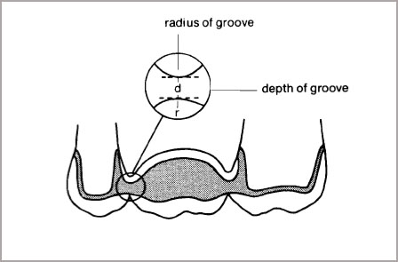
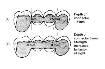
Fig. 7-2 Doubling the depth of the connector increases its strength. A connector of 1.5 mm depth (a) will be increased in strength by a factor of eight if the depth is increased to 3 mm (b).
For alterations in depth the deflection is inversely proportional to the cube of the change. Thus, doubling the depth of the connector increases its strength by a factor of eight (Fig. 7-2a and b).
Deflection is inversely proportional to the change in width. Doubling the width of a connector doubles the strength (Fig. 7-3a and b).
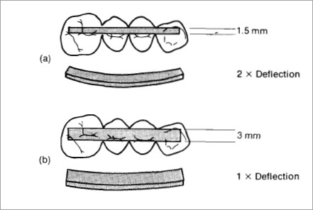
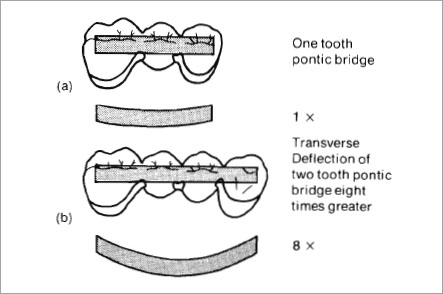
Fig. 7-4 If a one-tooth pontic bridge (a) is compared with a two-tooth pontic bridge (b) and the design of the pontics and connectors remains unchanged, then the two-tooth bridge will bend eight times as much as the one-tooth bridge.
For changes in the length of beams the deflection increases as the cube of the increase. Doubling the length of a span will allow eight times as much deflection for a given force. For example, if a one-tooth pontic bridge is compared with a two-tooth pontic bridge and the design of the pontics and connectors remain unchanged, then the two-tooth bridge will bend eight times as much as the one-tooth bridge (Fig. 7-4).
Stresses in fixed bridgework, although being highest around the connectors, can also involve the abutment crowns.
The stresses around posterior metal crowns and anterior metal-ceramic crowns have been analysed by Craig et al. (1967) and Farah and Craig (1975).
In the molar crowns they found that with bilateral occlusal loading the stresses in the crown were compressive along the cusp line C-D and changed from compression to tension along the central fossa line A-B (Fig. 7-5). Tensile stresses near the approximal margins of the crowns also increased with extra loading and would induce microleakage at the margins if the tensile stress was sufficient to fracture the cement film. They concluded that:
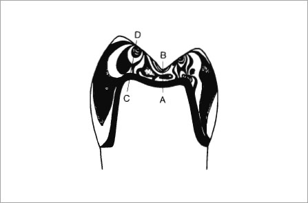
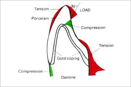
Fig. 7-6 When a metal-ceramic crown is loaded at an angle 30° to the vertical axis, very high tensile stresses occur on the lingual surface adjacent to the gold-dentine junction. This area of porcelain must be fully supported by metal and if the length of the coping or pontic is insufficient (< 2/3 height of the anatomical crown) the incisal edge of porcelain is easily broken or may even crack due to thermal shock.
- It is desirable to have multiple point contact when an antagonistic tooth occludes with the abutment crown, to reduce stress concentrations near the central fossa of the restored tooth.
- Full shoulders or their equivalent (e.g. deep chamfer) on complete crowns are recommended.
- Reduced cusps should be rounded on the preparation, to avoid the development of high compressive stresses on the interior surface of the crown, which may induce post-operative pain.
- Deep developmental grooves carved near the centre of the tooth should be avoided, as they will tend to produce deleterious stress concentrations.
An upper central incisor simulating a gold-porcelain crown when loaded at an angle of 30° to the vertical axis produced very high tensile stresses on the lingual surface adjacent to the gold-dentine junction (Fig. 7-6). In addition, tensile stresses were observed on the facial surface of the incisal edge. The importance of supporting the porcelain by metal in these two areas is vital and the coping must have sufficient incisal length and depth of shoulder on the lingual.
Stresses on the Anterior Bridge
Occlusal forces applied to anterior fixed bridges are even more complicated since they are subject to much more lateral stress during incisive movements. The connectors cannot be regarded as a simple beam since in this case the depth and width are related to the direction of occlusal stresses which can vary from a vertical thrust to angles of 45° or more, depending upon the relationship and depth of overbite of the incisors. Dimensions of the connectors should therefore be as great as possible and extended as far lingually as the occlusion allows. Failure to provide the proper depth in an anterior connector is a frequent cause of breakage particularly where the maxillary central incisors are splinted together in this very high stress-bearing area.
The basic design of bridges has been discussed by Shillingburg et al. (1976) and Miller (1977) and the effect of crown-root ratios and periodontal factors are outside the scope of this book. The technician is presented wirh preparations on which he has to construct metal-ceramic bridges. A knowledge of design and its biological implications is vital if he is to compensate for any inadequacies in preparation.
The design factors for metal-ceramic bridges may be summarised as follows:
Design for the Anterior Fixed Bridge
- Connectors should have the maximum depth occluso-gingivally without impinging on the gingival tissue (Fig.7-7a).
- Linguo-facial flexion will be resisted by extending the connectors as far lingually as possible (Fig. 7-7b). Optimum distribution of stress occurs when the ceramo/metal junction is located to the lingual of the approximal contact.
- The approximal strut of metal should be made in corrugated form. A corrugated shape is stronger for most materials than the same thickness of material in the form of a straight beam (Fig. 7-7c).
- Where the occluso-gingival depth on the bridge is small, connectors should be extended onto the occlusal surface.
- The ratio of the radius of the groove on the connectors to its depth should be as large as possible (Fig. 7-1).
- High tensile stress can be incurred at the linguo-cervical area of the abutment crowns. This area must be reinforced with metal and not porcelain. Thin cervical margins can easily distort (Fig. 7-7d) (Stein and Kuwata, 1977).
- Anterior bridges involving more than one pontic should have the lingual strut of metal extended to the surface where space is limited (Fig. 7-7e). Connectors may be extended to the surface at the joint area only, providing metal thickness is adequate (Fig. 7-7f).


Figure 7-7b

Figure 7-7c
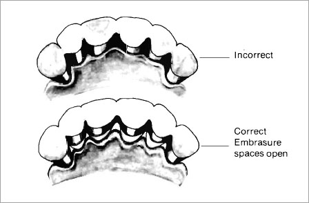
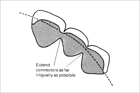
Figure 7-7e
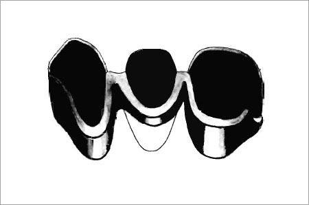
Figure 7-7f
Fig. 7-7a to f (a) Connectors should have the maximum depth occluso-gingivally without impinging on the gingival tissue. (b) Linguo-facial flexion will be resisted by extending the connectors as far lingually as possible. (c) Connectors should be made in corrugated form for additional strength. (d) High tensile stresses may occur at the linguocervical area of the abutment crowns. When the metal collars are too thin flexure may occur. This area must be reinforced with metal to prevent distortion of the cervical margins. (e) Anteriors connectors involving more than one pontic should have the lingual metal extended to the surface. (f) For maximum aesthetics and where the metal substructure is of adequate thickness (2.5 to 3 mm) the connectors may be extended to the surface at the joint area only.
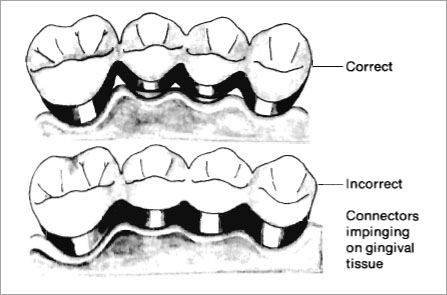
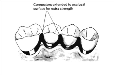
Figure 7-8b
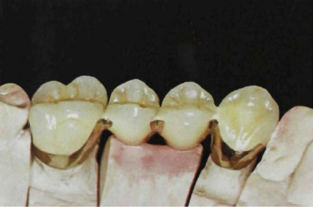
Figure 7-8c
Fig. 7-8a to c (a) Connectors should have the maximum depth occluso-gingivally without impinging on the gingival tissue. (b) Where the occluso-gingival depth is limited, connectors should be extended onto the occlusal surface. (c) Optimum aesthetics will be obtained if the connectors are extended to the surface at the joint area only, providing the metal substructure is of adequate thickness.
- Connectors should have the maximum depth occluso-gingivally without impinging on the gingival tissue (Fig.7-8a).
- Where the occluso-gingival depth on the bridge is small, connectors should be extended onto the occlusal surface and the approximal strut of metal made in corrugated form (Fig. 7-8b).
- The ratio of the radius of the groove on the connectors to its depth should be as large as possible (Fig. 7-1).
- Each additional pontic may increase the stress on the bridge by up to eight times. Connectors must therefore be increased in dimensions and if necessary metals with higher yield strength and modulus of elasticity used. Base-metal alloys do not allow a reduction in thickness of much more than 6% since their modulus of elasticity and yield strength is still too low to permit major changes in design.
- Where occluso-gingival space is adequate optimum aesthetics will be obtained if the connectors are only extended in the joint area (Fig. 7-8c).
A guide to the minimum thickness of connectors is important to the technician, since the theoretical aspect of design does not always give him a practical answer.
Minimum thickness of connector for the anterior bridge should be 2.5 mm occlusogingivally and 2.5 mm facio-lingually. Dimensions may be decreased to 2.0 mm in small single pontic bridges.
Minimum thickness of connector for the posterior bridge should be 2.5 mm occluso-gingivally and 2.5 mm bucco-lingually. However wherever possible the maximum thickness of metal should be used commensurate with the maintenance of gingival health.
A metal-ceramic pontic must fulfill certain requirements:
- It must be easily cleaned.
- It must have minimal contact with the gingival tissues without causing food impaction.
- It must produce the illusion of looking like a tooth.
- It must be in occlusal harmony with the opposing teeth.
A number of preformed porcelain facings are available and these have been well described by Shillingburg et al. (1976). The metal-ceramic pontic has become the material of choice since it allows great flexibility in design and aesthetics.
There are three designs which can be used for the pontics, of which only one is really suitable for metal-ceramic work.
Saddle. This pontic occupies the entire area of the missing tooth. It fills the embrasures and overlaps the ridge, resulting in a large concave contact (Fig. 7-9). This is the most undesirable shape for a pontic and should never be used since it cannot be easily cleaned.
Ridge Lap. This pontic still occupies most of the area of the missing tooth except it eliminates the concave contact area of the saddle pontic. It is the most useful metal-ceramic pontic and in our laboratory we have found that certain design features are essential for success (Fig. 7-10a). The contact areas with the ridge should be in glazed porcelain (Fig. 7-10b). The lingual surface should just contact the crest of the ridge and then slope towards the occlusal surface. Contact on the buccal surface should be minimal and triangular in form (Fig. 7-10c). The embrasures should be open for cleaning with dental floss or wood points and all tissue contact should be without pressure. Some designs for this pontic show tissue contact area only on the buccal slope, leaving a space at the ridge area. This design (Fig. 7-10a) can cause a food trap and patients object to it. To avoid this, the pontic must be in contact in the lingual area with the crest of th e ridge (Fig. 7-10d), any food can then be swept away by tongue action. In essence it is a small triangular tissue contact area with all other surfaces being convex. The ridge lap pontic can be made with optimum aesthetics on the buccal and facial surfaces.
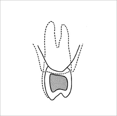
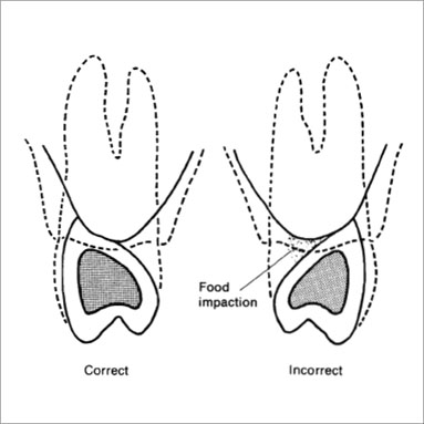
Figure 7-10a
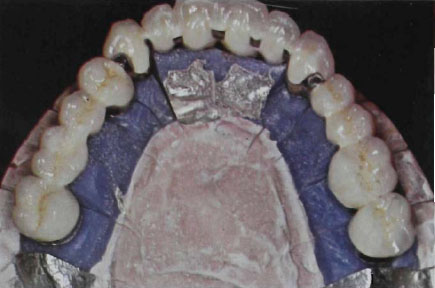
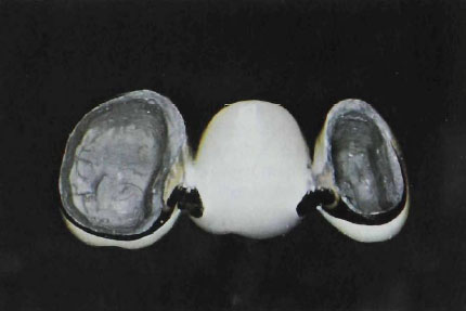
Figure 7-10c
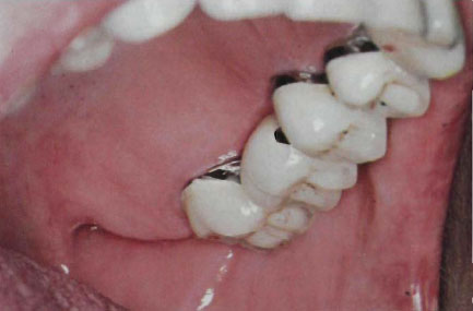
Figure 7-10d
Fig. 7-10a to d The ridge lap pontic. Dotted line indicates original area of tooth and supporting tissue. (a) Diagram of the correct and incorrect area for tissue contact. If the pontic only contacts the buccal slope there is a tendency for food to become impacted in the ridge area. The correct design should allow the pontic to contact the crest area of the ridge. (b) Contact areas should be made in glazed porcelain as illustrated in this full mouth rehabilitation. (c) Glazed molar showing correct ridge contact area with open embrasure. (d) Metal ceramic bridge from Figure 7-10c cemented in the mouth showing pontic which is just in contact with the crest of the ridge.
The edentulous ridge should have been prepared for the pontic. Ridges with uneven surfaces or small bumps that cannot allow the use of a convex surface pontic should be shaped with surgical knives, high-speed diamonds or by electro-surgery. Gingival tissue around the abutment teeth should be removed if it has formed a prominent “cuff”. Pontics should not be inserted on tissue that has become inflamed by previous bridges of incorrect design. Inflamed or high gingival cuffs can cause the connectors to be made with inadequate depth and result in weakening of the joints. All metal framework should be tried in the mouth and checked for fit, occlusal clearance and correct embrasure spaces, prior to baking the porcelain. Porcelain pontics should be checked again with pressure indicating paste for correct tissue contact prior to final glazing.
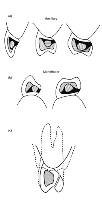
Designs for full porcelain coverage are shown in Figure 7-11a and b. The width of occlusal table should be maintained for ideal cusp fossae relationships. For optimum aesthetics the space for porcelain should be 0.3 mm for opaque and 1.2 mm for dentine and enamel. The metal supporting structure should follow the contour of the original teeth and support the porcelain so that uneven thicknesses are avoided (Fig. 7-11c). Porcelain thickness can be increased in non-stress bearing areas such as the ridge contact areas, with a resultant improvement in aesthetics due to higher light transmission at the cervical area (Monograph III, McLean, 1979). Approximal contacts should also be in porcelain for optimum aesthetics.
Designs for metal coverage of the lingual and occlusal surfaces are shown in Figure 7-12. Full metal coverage is indicated where the occluso-gingival space is limited and extra strength is required. Many clinicians also prefer to develop occlusion in gold rather than porcelain. In our laboratory, full porcelain coverage is preferred, particularly in the mandibular restorations where massive areas of gold are unsightly. The merits of porcelain versus gold occlusions have been discussed (Monograph III, McLean, 1979).
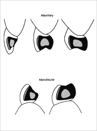
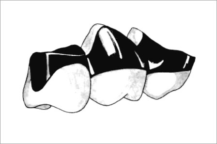
Fig. 7-13 Gold to tissue contact should always be avoided. The gold alloys used for ceramic bonding tend to oxidise rapidly and attract plaque.
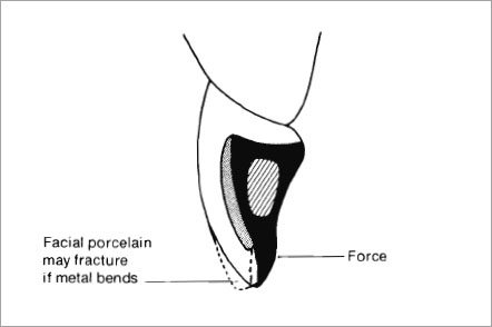
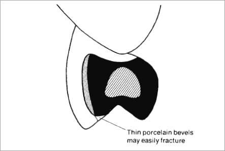
Figure 7-14b
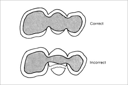
Figure 7-14c
Fig. 7-14a to c (a) If the metal is extended too far incisally it may be too thin and distort, causing fracture of the porcelain. (b) Never apply porcelain to a bevelled edge. (c) Do not reduce the width of the metal section of the pontic. Unsupported porcelain will break and this is a frequent sight on the lingual surface where porcelain thickness exceeds 1 mm.
Wherever possible, designs as shown in Figure 7-13 should be avoided. Gold to tissue contact is undesirable with the goldplatinum-palladium alloys since metal oxidation can cause increased retention of plaque when compared with glazed porcelain.
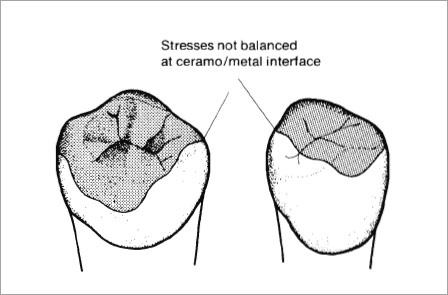
The ceramo/metal interface should never be placed in areas of occlusal contact when the mandible is at rest. Porcelain may also fracture if the metal is extended too far incisally (Fig. 7-14a). All ceramo/metal interfaces should preferably be at right angles and porcelain should never be applied to a bevelled edge (Fig. 7-14b).
Full support must be given to the porcelain on the occluso-lingual surface and under no circumstances should an attempt be made to reduce the cost of metal by reducing the width of the metal section of the pontic (Fig. 7-14c).
The use of partial occlusal coverage of abutment crowns is also deprecated (Fig. 7-15
Stay updated, free dental videos. Join our Telegram channel
VIDEdental - Online dental courses


