Chapter V
Cast Metal-Ceramic Crown
Construction
Construction of Gold Alloy Coping
The accuracy of fit of a cast gold coping is dependent upon a number of factors:
- Shrinkage or distortion of wax pattern.
- Strength and surface roughness of investment.
- Thermal expansion of investment.
- Contraction of the alloy after casting.
The accuracy and surface smoothness of the wax pattern is the first weak link in this chain. Failure to form the pattern correctly will introduce an error that is multiplied at each stage of the casting procedure.
Phillips (1973) considers that distortion of the wax pattern is probably the most serious error when removing a pattern from the die. Distortion can arise from thermal changes and the release of stress in the pattern. These stresses can be induced due to the natural tendency of the wax to contract upon cooling and from manipulative variables such as changes in shape during moulding, carving, pooling or removal of the pattern from the die. Rapid heating of the wax and failure to “heat soak” it sufficiently to attain a uniform temperature can result in an un-homogeneous structure. Addition of molten wax may also introduce cooling stresses. A wax pattern can also distort if stored for a long period since it may flow under its own weight. Forming an accurate wax pattern requires the following precautions:
- Uniform heating of the wax.
- Minimal manipulation.
- Minimal corrections made by adding wax.
- Immediate investment of pattern after completion of waxing.
Asgar (1960) found that full crowns waxed with hard blue inlay wax did not fit perfectly on their dies and that the best fit was obtained by using a dual wax technique. He recommended waxing the occlusal two-thirds of the pattern with soft 28-gauge partial denture green wax, and the cervical one-third with regular blue inlay wax. The apparent success of this dual wax technique may be explained by the fact that the forces of hygroscopic and setting expansion acting on the pattern within the investment are equal in all directions. However, the resistance by the wax pattern to these forces is not always equal. Asgar found that if a crown is waxed entirely with hard inlay wax, the occlusal portion offered more resistance to the forces of expansion than the thin cervical portion (Fig. 5-1). As a result, the wax pattern was distorted and the casting was either too tight at the occlusal, or open at the cervical margin. The use of a softer wax for the occlusal two-thirds of the pattern resulted in less resistance to the forces of expansion and minimum distortion of the pattern during setting and hygroscopic expansion of the investment (Fig. 5-2).
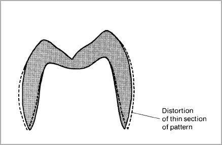
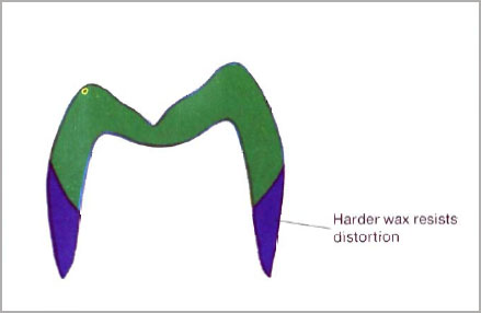
Fig. 5-2 Dual inlay wax technique. The harder wax at the cervical margin will resist distortion more then the soft occlusal wax.
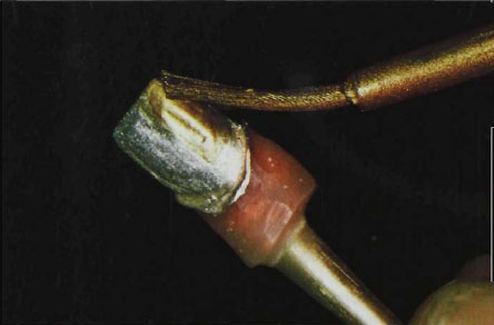
Fig. 5-3 Application of die spacer to a silver-plated die. Silver coat overlaid with alternate coats of gold die spacer.
Eames et al. (1978) have shown that the use of a die spacer can improve the fit of castings. He used up to five coats of die spacer to produce a coat or “spacer” of approximately 25 microns thickness. The material is supplied in two colours, silver and golda and it is easy to see whether each coat has been fully covered by the next one. A die spacer provides a space or “shim” for the cement and is particularly useful for near-parallel preparations for which metal-ceramic crowns are being manufactured.
The system of using alternate coats of silver and gold die spacer is shown in Figure 5-3. The spacer must not be applied to the shoulder or cervical margins of crowns. The advantages of relieving the die or etching the crown are that castings will seat more completely because internal stress areas are substantially relieved, and more space is provided for the thickness of cement.
Etching the fit surface of the coping with Aqua Regia can also produce a space of uniform thickness. The crown or coping should be protected on the occlusal surface with wax which should also cover the margin to a depth of 1 mm. Acid etching for five minutes will then remove around 15 microns of metal and a 25 micron space can be created by increasing the time to seven minutes. The casting should then be flushed in boiling water, scrubbed clean with a brush and flushed in strong ammonia solution to remove any residual silver chloride which could affect the bonding of the cement.
Of the two techniques, the use of the Eames die-spacer technique is the most simple and has proved very successful in our laboratory.
Three techniques may be used for forming the pattern:
- Sheet wax technique.
- Wax dip technique.
- Full wax contour technique (gold occlusal coverage).
This method may be used on either electroplated or stone dies. For illustration purposes the wax will be laid down on an electroplated die.
After trimming the die as described on page 72, apply five coats of die spacer to the axial walls only and allow to dry. Coat the die with a separator such as “Waxit”b or “Kerr’s microfilm”c and blow off any excess (Fig. 5-4).
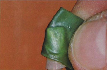
Fig. 5-5 Soft green wax (0.5 mm gauge) adapted to die with fingers.
Apply a sheet of soft green waxd 0.5 mm gauge to the die as if a platinum foil matrix is to be made. Gently adapt it with the fingers around the die until the two surfaces meet on the opposite side from where it was applied. Squeeze the edges together and the wax should now envelop the preparation like a cylinder (Fig. 5-5). Proceed to adapt the occlusal surface and seal the wax edges with a hot burnisher; anyexcess will be removed automatically. Repeat the operation on the approximal joint and the wax coping should now be tightly adapted on the die. Remove any green wax from the shoulder area with a blunt Le Cron carver (Fig. 5-6).
Transfer the die to the articulated working cast and check occlusal clearance. Make sure there is room for at least 1 mm thickness of porcelain. If the incisal edge is too short or narrow due to a conical preparation, then it must be built up in wax and cast in metal to give support to the porcelain. Cusps or incisal edges should be restored in blue wax (Fig. 5-7). The second stage of the dual wax technique involves the building of a cervical collar of hard blue inlay wax.
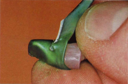
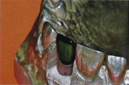
Fig. 5-7 Blue wax used to build up incisal edge or cusp outlines to support porcelain. Porcelain should never be used to fill in missing tooth areas of the preparation.
Flow in hard blue inlay waxe at the cervical margin with a hot beaver-tail burnisher to form a complete ring around the green wax coping. Chamfer the wax from the axiogingival wall to a knife-edge at the labial cervical margin. The labial edge may be formed by using a warm beaver-tail burnisher and stroking the wax towards the margin (Fig. 5-8). Form the approximal and lingual collar by trimming the wax from a point just distal to the contact area. Allow the wax to rise up towards the lingual area so that it will conform to a classical coping design as illustrated in Figure 4-13a. The lingual section should form a collar not more than 3 mm high which then tapers off at the approximal.
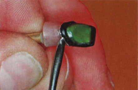
Fig. 5-8 Hard blue inlay wax used to reinforce cervical area and form the lingual collar.
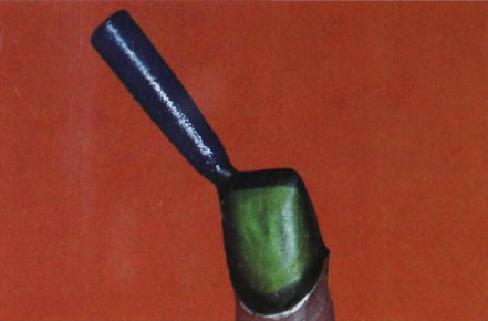
Figure 5-9a
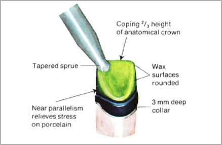
Figure 5-9b
Fig. 5-9a and b (a) Completed wax pattern after polishing and spruing. The facial surface is finished to a knife edge at the cervical margin and the coping should conform to the classical outline of a jacket crown preparation. (b) Diagram of correct waxing of lingual collar.
The joint for the porcelain should be at a right angle and the collar must be finished with great care at the potential ceramo/metallic junction. A small spoon excavator is a very useful instrument for doing this since it will produce a smooth curve from 2. the axial wall to the butt joint.
One of the objections to waxing only the coping and collar prior to developing the lingual occlusion is that the lingual butt joint could be placed incorrectly in relation to the overall contour of the tooth. Providing the incisal guidance path is observed carefully on the articulator, this has not presented great problems in our laboratory. By contrast, if technique No. 3 is used (the full wax contour technique) the carving of the coping to exact thickness (0.5 mm) is made much more difficult.
Prior to finishing the margins, check the wax pattern for any thin spots. These are easily observed because of their greater translucency when viewed in transmitted light.
A gold casting is only as good as its margins and the finishing of a wax pattern is critical.
Examine the margin by viewing it from an apical direction and see whether the wax is correctly adapted to the finishing line marked in red pencil.
Lift off the pattern, replace it and check for defects:
- Overwaxed margin. Wax will extend as a definite feather edge which can break or distort on withdrawal. A casting made from such a wax-up could either be short (breakage of wax on withdrawal) or not seat due to the feather edge distorting.
Correction. Warm a beaver-tail burnisher and gently remove the wax back to the finishing line. Lift off pattern and check again for feather edges. An ideal edge should be sharp angled and not rounded. - Open margin. The open margin is a major disaster in waxing techniques. It is nearly always caused by wax shrinkage.
Correction. The dual wax technique should take care of this but if there is a sign of an open margin when viewed apically, it is often good practice to readapt the pattern in a water wax swager. Alternatively use a hot beaver-tail burnisher to re-establish the margin. A continuous swaging action should cause the wax to flow and re-seal the edge. - Short margins. A common fault in waxing techniques; often produced by excessive zeal in finishing the margin, the wax being dished out at the cervical. Correction. Add more hard blue inlay wax and re-seal the margin using a beaver-tail burnisher.
Incorrect Contour
Although the wax can be finished accurately to the margin, it might not be finished with the correct contour at the cervical. It is easier to remove wax rather than gold so that a careful check should be made of the lingual and approximal contour. There should be no thick or rounded margins and the margin of a wax pattern should present a fine edge (Shillingburg et al., 1976).
Finishing the Pattern
Avoid ripples or surface irregularities on the collar since these will all be reproduced in the gold casting and are difficult to eliminate. Prior to spruing, the collar may be finally polished with a cotton-wool pellet soaked in a release agent such as Kerr’s microfilm. Polishing should be lightly done and under no circumstances used as a means to smooth over gross irregularities (Fig. 5-9a and b).
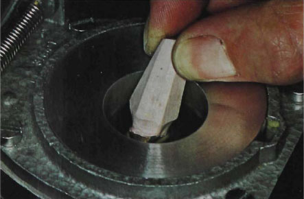
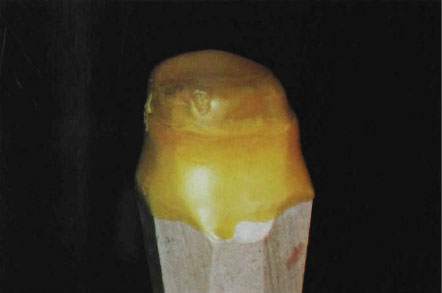
Figure 5-10b
Fig. 5-10a and b (a) Dipping the die into the wax bath. (b) Wax after cooling on die leaves a thickness of approximately 0.5 mm.
The Wax Dip Technique. Mandibular First Molar with Labial and Lingual Chamfer with Gold Collar
This technique may be used with eitherThis technique may be used with either electroplated or stone dies. The technique will be illustrated on a stone die.
Coat the axial walls of the die with five coats of die spacer and allow to dry. Apply a release agent such as Waxit or Kerr’s microfilm and remove excess with an air blast.
Apparatus
Green waxf is melted in a wax bathg at 90°C and should be in a fluid condition prior to wax application. Hold the die vertically over the bath and dip it into the bath until the wax covers the cervical margin (Fig. 5-10a). Immediately remove die. The wax will cool and one dip should leave a coating of approximately 0.5 mm of green wax attached to the die (Fig. 5-10b). The thickness of the wax may be checked with millimetre calipers. Remove all the wax from the shoulder area and check that the coping can be easily removed from the die. Apply more release agent to the die, re-seat the coping and fill in the cervical area with hard blue inlay wax to form a collar approximately 1 mm high on the buccal shoulder rising to 3 mm high on the lingual.
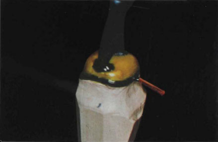
Figure 5-11a
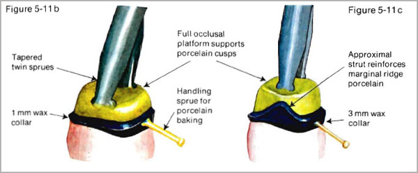
Fig. 5-11a to c (a) Completed wax coping after addition of cervical collar in hard blue inlay wax. (b) Diagram of correct wax-up of mandibular molar coping. (c) In cases with increased vertical height approximal strut may be added to increase vertical support. However too great a thickness of metal can reduce approximal translucency (see Fig. 4-22).
Carve the cervical collar with a blunt knife such as a Le Cron carver and trim it back to the cervical finishing line. Use a warm beaver-tail burnisher to finish the edge. Carve the finishing line for the porcelain with a sharp knife or spoon excavator starting with the buccal surface first. The buccal collar must be not less than 1 mm in thickness. Gradually increase the thickness of the collar once the margin passes the approximal contact areas until a crest of 3 mm is reached on the lingual surface.
Check the fit and thickness of the coping and finish the margins as described for the “sheet wax” technique. The completed wax coping is illustrated in Figure 5-11a and b and conforms to the coping design previously described in Figure 4-21. The addition of an approximal strut is illustrated in Figure 5-11c and is often required in the longer maxillary teeth to support the porcelain marginal ridges.
This technique may be used on either electroplated or stone dies. For purposes of illustration an electroplated die will be used.
Coat the axial walls of the die with five coats of die spacer and allow to dry. Lubricate the surface with a release agent. Build up the coping with two or three layers of green wax using the “wax dip” technique just described (Fig. 5-10). Trim the wax away from the shoulder area and refill with hard blue inlay wax. Transfer the die to the articulated working cast and build up the approximal contacts with the adjacent teeth in blue inlay wax. Establish the occlusal relationships with the opposing teeth and then the occlusal platform can be outlined. Cusp form may then be developed using the “wax additive” technique in which wax cones are placed and then joined by marginal ridges (Fig. 5-12). Detailed techniques for establishing occlusion in gold alloy castings have been described by Dawson (1974), Guichet (1969), Ramfjord and Ash (1971), Shillingburg et al. (1976), Stallard and Stuart (1963) and Thomas, P. K. (1976).
Outline the area for veneering with porcelain by scratching a mark on the buccal surface. The outline mark should start at the approximal surface and be placed as far lingually as possible without interfering with the contact area. At the occlusal surface the wax should be removed from the tip of the buccal cusp to conform to the outline given in Figure 5-13. Porcelain should not be recessed in the way acrylic is boxed in. A recess will form a re-entrant angle which is difficult to “wet” with porcelain (Fig. 4-4). The final outline of the pattern will be completed by marking out the cervical collar (Fig. 5-13). The cervical area may also be finished to a knife-edge chamfer finish for direct porcelain contact with the shoulder.
The wax should now be removed from the veneering area by cutting depth grooves with a spoon excavator. The depth cuts should be at least 1 mm deep if reasonable aesthetics is to be obtained in the porcelain. Start the first depth cut in the midline, and then cut into the pattern outline form (Fig. 5-14). It is a simple procedure to remove the remaining wax from the buccal surface and at the same time to leave a 90° butt joint for the porcelain. This joint can be sharpened by using a scalpel, however, the internal area should exhibit a smooth chamfer as it reaches the broad buccal face of the wax (Fig. 5-15). This will ensure that there are no undercuts or sharp angles where it is difficult to fuse porcelain successfully.
The finishing of the margins and checking the accuracy of the pattern have been described in the “wax sheet” technique.
Full Wax Contour Technique – Mandibular Teeth
The same procedure as described above should be employed for the mandibular premolars and molars. However, because the lower buccal cusps are to be used as “plunger” or “stamp” cusps to occlude in the fossae of the upper posterior teeth, it is necessary to construct these in gold alloy. This will result in the porcelain being boxed in like acrylic resin (Fig. 5-16). As explained previously, this is not a desirable state of affairs since porcelain is being fired into re-entrant angles even though these are smoothly contoured. However, to mitigate the stress that may develop in the porcelain, it is essential to reinforce the buccal cusps with at least 1.5 mm thickness of metal (Fig. 5-16).
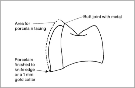
Fig. 5-13 Outline of area for porcelain veneering marked on buccal surface.
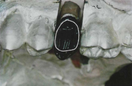
Fig. 5-14 Depth cuts made for removal of wax from facing area.
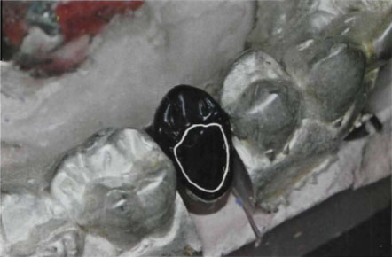
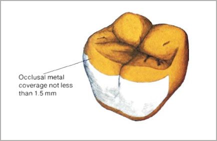
Fig. 5-16 Where cusps are being restored in gold the metal must be at least 1.5 mm thick in order to prevent metal flow and breakage of porcelain.
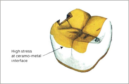
Fig. 5-17 Partial coverage of occlusal surfaces although improving aesthetics does not allow the development of a balanced stress system in the metal/porcelain combination.
Partial Occlusal Coverage with Metal
There are occasions where partial coverage of the occlusal surface with metal is essential. For example, where denture rests are to be inserted or precision attachments incorporated. Partial coverage of metal occlusal surfaces with porcelain has also been advocated for aesthetic reasons. Mesial aspects of teeth where opposing cusps do not contact are obvious sites for using the improved aesthetics of porcelain (Fig. 5-17). However, such procedures are far from ideal since, as explained on page 192 the balancing compressive stresses set up in the porcelain on cooling are not used to full advantage. Partial coverage of occlusal surfaces with metal can also make the appearance look even worse since the porcelain may highlight the metal surface in the same way as precious stones set in a gold surround. In the latter case, every effort is made to draw attention to the stone but in the case of a tooth quite the reverse situation should be in the ceramist’s mind.
Selection and Attachment of Sprues
The design of the sprue channel leading from the crucible to the mould cavity makes a vital contribution to the success of the casting. The sprue channel provides an escape for the wax during the early stages of the burnout procedure, and then determines the way the metal will fill the mould. The sprue should allow the metal to flow into the mould with the minimum amount of turbulence in order to avoid entrapped gas and resulting porosity in the casting. The sprue also provides a reservoir of molten metal upon which the casting may draw during solidification, thereby compensating for the loss of volume when the metal shrinks on cooling. The main requirements when attaching sprues to a wax pattern may be summarised as follows:
- The sprue should be large enough to prevent the metal freezing in it before the metal in the casting has solidified. Ideally the sprue diameter should be as thick as the thickest section of the pattern.
- The sprue should provide a reservoir of molten metal.
- The direction of the sprue should allow the metal to flow into the mould without major changes of direction (Fig. 5-18).
- The sprue must not be attached to thin sections of the wax pattern since the metal may freeze too quickly if entry is restricted (Fig. 5-19).
- The sprue should not direct the flow of metal onto fine edges or thin sections since the investment surface might break down.
- Sprues should be attached to the pattern with a smooth fillet that allows the metal to sweep evenly into the mould (Fig. 5-18). When more than one sprue is used they must leave the crucible former from a common point.
- Wax or metal sprues must be smooth and even to prevent “bumpiness” when metal traverses the sprue channel.
- Sprue lengths should not exceed 18 mm and where possible shorter sprues of 6 to 10 mm should be used. However, the furthest point of the pattern should not be more than 6 mm from the end of the investment ring, otherwise escape of gases is made more difficult and back pressure porosity may occur in the casting.
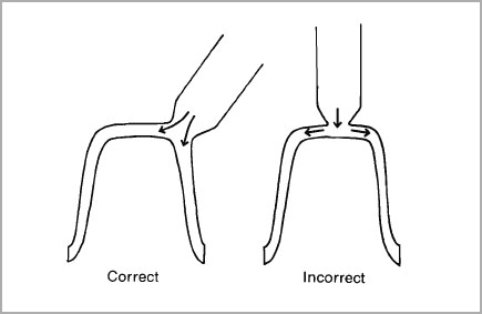
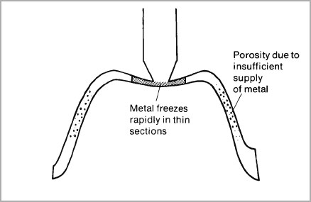
Fig. 5-19 Do not attach sprues to thin sections of the pattern since the metal may freeze too quickly.
In larger castings such as multi-unit splints or bridgework, it may be necessary to provide vents to permit gas to escape rapidly from the mould cavity when the metal casting is made. In the case of a metal-ceramic coping, gas may move through the investment in all directions but it can be trapped in the inner surface of the coping since there will only be one exit point at the orifice. The rate of escape of the gas is also dependent upon the porosity of the investment and with very dense investments residual gas may become entrapped in the casting. This can result in pin-holes in the casting and suck-backs in the sprue rods (Fig. 5-20). In our laboratory the use of venting has not proved necessary with the high gold content alloys but where base-metals or high palladium content alloys are used then venting of the mould cavity could prove beneficial.
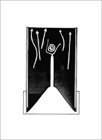
Fig. 5-20 If gas cannot escape from the internal surface of the crown mould it may result in suck-back in the sprue rod. Venting can prevent this from occurring.
Technique for Attaching Sprues
There are many designs and techniques for attaching sprues to wax patterns. The methods illustrated here have been used in our laboratory for many years and have evolved from a study of the principles of spruing outlined above. The basic principle involves the use of 3.5 mm diameter sprues tapered to a cone where they enter the pattern. The entry point is selected so that the metal can flow into the casting with the minimum of turbulence. There will be no danger of the metal freezing at this point during casting provided the length of the tapered section is not too long and the minimum diameter at the junction point with the pattern is not less than half the diameter of the original sprue (Fig. 5-21). The large diameter sprue acts as a reservoir and the restricted cone entry point prevents suck-back of metal. We have found that any porosity occurs in the coned section and not in the casting so that high densities may be obtained at the point of entry (Fig. 5-21). It should be noted that where the cone meets the pattern, additional wax is added to allow the gold to sweep into the casting along a smooth flared-out channel.
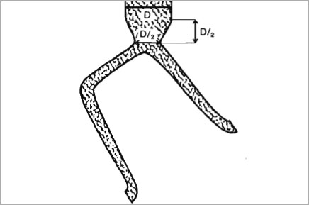
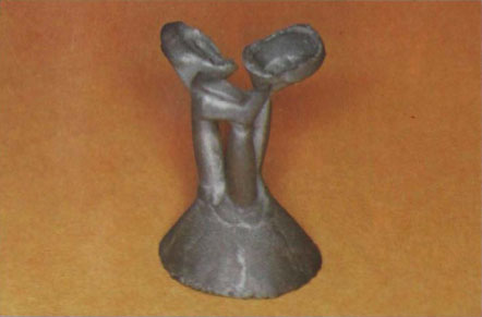
Fig. 5-22 Attachment of sprues to multiple units using a central reservoir located at the apex of the crucible former.
In the case of bridgework or multi-unit crowns used for fixed splinting, sprues are attached to each unit and fan out from a central reservoir which is located at the apex of the crucible former (Fig. 5-22). This system is different from the T-bar system illustrated in Figure 5-23 where a feeder sprue runs into the horizontal T-bar section. The main objection to this design is that the gold cannot flow straight into the pattern but has to change direction in the T-bar unit. The design and construction of wax patterns for bridgework is discussed in Chapter VII.
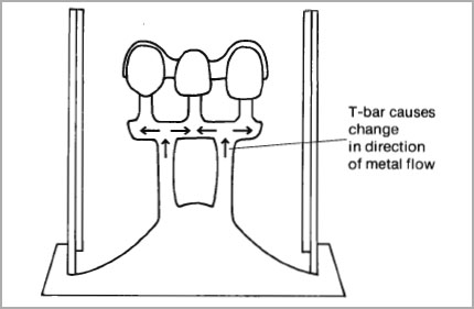
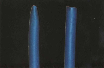
Fig. 5-24 Soft wax sprue rolled in fingers to form tapered end.
Select a 3.5 mm rod of soft wax of just over 2 cm length. Soften the end and roll it into a cone with the fingers (Fig. 5-24). Attach the apex of the wax cone to the thickest part of the incisal edge of the coping with a hot beaver-tail burnisher. Do not overheat the wax coping but allow the soft profile wax to flow over the surface so that the sprue fans out as it enters the wax pattern.
Cover the pattern with a sheet of rubber dam and hold the sides with the thumb and forefinger. Using the thumb and forefinger of the other hand, gently squeeze the die so that the tips of the fingers meet, exerting an upward pressure on the coping. As soon as the coping starts to lift from the die, grasp the sprue and gently withdraw. Do not attempt to pull the pattern off the die with the fingers and never remove a wax coping with the sprue.
Positioning of Patterns and Sprues in Casting Ring and their Effect
on the Shrinkage of the Casting
The correct positioning of patterns and sprues in the casting ring can markedly influence the density of the casting. Molten alloys solidify when the latent heat of fusion has been transferred to the surrounding investment. If this transfer of heat occurs in different areas and in irregular sequence, the contraction coupled with the solidification of the metal will cause piping (porosity) in essential parts of the casting (Weber, 1977). Porosity occurs in every casting but should be restricted to areas such as sprues which do not affect the surface texture of the casting.
Ideally, solidification of the metal should start in the thinnest sections of the pattern and continue through the thicker sections, until finally, the metal in the sprue freezes (Fig. 5-25a and b). The casting should then be almost free of porosity since at every stage of the solidification of the metal, molten alloy will be available in adjacent sections to take up any contraction. The tapered sprue illustrated in Figure 5-21 will then act as a true reservoir. The cooling down of the metal will also be affected by mould temperature. The main factors causing one section to solidify before another and which influence the density of the casting are:
- The lower the temperature of the alloy entering the mould, the quicker it will cool.
- The lower the temperature of the investment, the quicker the alloy will cool (Fig. 5-25c).
- The relationship of one section of the pattern with another, particularly where the surface area is large in relation to the mass of the pattern.
Attachment of sprues to the pattern and their position in the investment ring should take into account the above factors and be related to the thermal gradients occurring in the investment ring.
After the alloy is cast, a thermal centre is formed in the mould approximating to the geometrical centre of the investment ring. The investment in this area will remain hotter than the surrounding areas and the molten alloy will always solidify last in the thermal zone. If the pattern is located directly in the centre of the thermal zone, then there is a riskthat the peripheral feeder sprues could freeze prematurely and molten metal would no longer be available to feed into the mould (Fig.5-26a). By contrast, if the pattern is placed outside the thermal zone with the feeder sprues in or near to the zone, an ideal state of affairs is created. The feeder sprues will solidify last and continue to replenish the casting with molten metal as it solidifies (Fig. 5-26 b).
The temperature variations in a mould relative to the time out of the furnace have been plotted geometrically. It was shown that in a given plane, the temperature is uniform at all points at an equal radius from the centre of the mould (Weber, 1977). Therefore in order to ensure the same conditions for all patterns, they should be placed equidistant from the centre of the investment ring and in the same plane (Fig. 5-27). Patterns placed within the radius would cool in less favourable conditions (Fig. 5-27a).
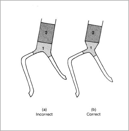
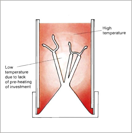
Fig. 5-25c Even where a correctly-shaped sprue is used, if the mould has been insufficiently preheated the sprue channels may still solidify first.
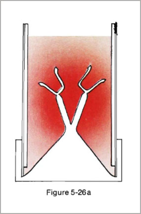
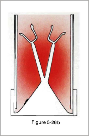
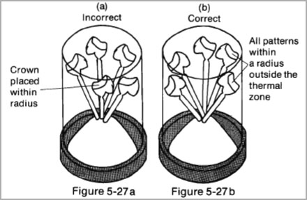
Fig. 5-27a and b (a) Unfavourable condition for placing patterns. One crown is placed within the radius and inside the thermal zone. (b) Favourable condition for placing patterns. (After Weber, 1977.)
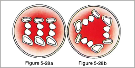
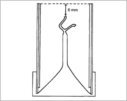
Fig. 5-29 Correct position for a single coping in the investment ring. The periphery should be 6 mm from the end of a standard investment ring.
The positioning of bridge units is also affected by the thermal zone. If the patterns are placed close together within the zone, then the thick areas such as pontics will inhibit heat dissipation and result in porosity, since the feeder sprues may solidify first. This situation may even occur with single bridges placed centrally in the zone (Fig. 5-28a). If the bridge is positioned peripherally then the sprues can continue to feed in molten metal (Fig. 5-28b).
Attachment of Sprues to Crucible Former
Hold the sprue in a pair of tweezers and place the pattern against the crucible former for measurement. Adjust the length of the sprue so that the pattern is outside the thermal zone with the sprue running through the zone. For a single coping the periphery of the pattern should be approximately 6 mm from the end of a standard investment ring (Fig. 5-29). Soften the wax in the top of the crucible former and gently press the wax sprue into it. Check that the sprue is centrally placed in the ring prior to investment.
Exactly the same technique should be employed for the premolar or molar coping. However, in the case of a large molar coping it is advantageous to use twin sprues. Locate the sprues in the thickest part of the periphery of the occlusal table (Fig. 5-11).
Where more than one pattern is being invested at a time, the feeder sprue should be attached from a central point and the patterns placed in a radial plane around the investment ring (Fig. 5-27b and 5-28b).
Before investing the pattern it must be coated with a wetting agent such as “Waxit”h (Fig. 5-30). A wetting agent reduces the surface tension at the surface of the wax pattern and assists in producing a clean, smooth casting.
These agents should be lightly applied with a brush and any excess removed with a gentle blast of air. The pattern must be left to dry for ten minutes before investing takes place. Incomplete drying will result in rough castings.
The casting temperature of the alloys used in the metal-ceramic technique are too high (ca. 1100°C) for use with conventional gypsum-bonded investments. High heat will cause decomposition of the calcium sulphate and release sulphur into the mould which could embrittle the casting (Phillips, 1973; O’Brien and Nielsen, 1959).
The high temperature casting investments contain a binder consisting of a phosphate and a metallic oxide. Generally a magnesium phosphate is reacted with primary ammonium phosphate to produce magnesium ammonium phosphate, the crystals of which provide the “green” strength to the investment before heating. The amount and crystal size of the quartz or cristo-balite powder added determine to a considerable extent the setting and thermal expansion of the investment. When the investment is heated to its casting temperature, complex silicophosphates are formed which give the investment its “high temperature strength” (Phillips, 1973).
Phosphate bonded investments differ from the conventional gypsum-bonded types used for conventional gold alloys in that the concentration of the liquid controls the expansion. The liquid contains an aqueous suspension of colloidal silica and according to the proportions the setting expansion may be controlled within reasonable limits, e.g.
More expansion –
increase the liquid (silica sol) to water ratio.
Less expansion –
decrease the liquid to water ratio.
The most commonly used proportion is 3 parts liquid (silica sol) to 1 part distilled water. The overall liquid/powder ratio for the investment should then remain constant at 9.5 ml liquid to 60 grams of powder.
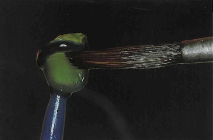
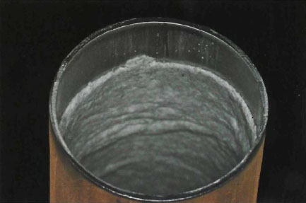
Fig. 5-31 Asbestos lining placed in casting ring just short of each end, or to a mark indicating investment level.
Method
- After spruing and mounting the pattern on the crucible former, use one layer of asbestos paper saturated with water to line the inlay ringi. The asbestos should be 3 mm short of each end of the casting ring (Fig. 5-31). The pattern is positioned against the casting ring to check correct length (Fig. 5-32).
- Mix 3 parts of Argivest No. 72 liquidj (or similar material) with one part of distilled water and dispense 9.5 ml of the diluted silica sol into a damp bowl used with the investing unit Degussa Multi-vac 3 illustrated previously in Figure 2-25.
- Add 60 grams of Argivest investment No. 72 powder and mix with a hand spatula. (Each 60 gm sachet mixed with 9.5 ml of liquid is equivalent to a liquid/powder ratio of 16 to 100.)
- Set timer on investing machine to40seconds and apply the lid to the mixing bowl. Connect the vacuum tubing and mechanically spatulate for the required time. The speed at which the mixer operates can affect the setting time. Chilling the liquid will lengthen the setting time.
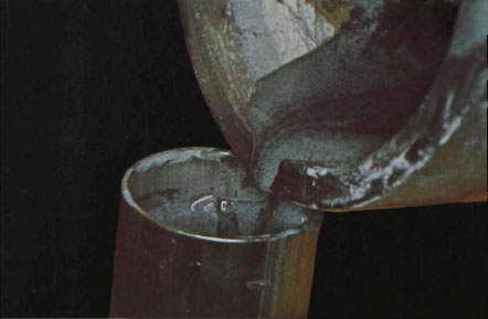
- Release the vacuum and vibrate the mix for a few seconds. Gently pour the investment down the side of the investment ring. Any re-entrant angles in the pattern should be painted with investment to prevent the trapping of large air bubbles (Fig. 5-33a and b).
- Continue pouring the investment until it is approximately 6 mm above the level of the pattern (Fig. 5-29).
- Additional expansion may be provided by submerging the investment ring in a water bath at 38°C for a minimum of 30 minutes but not more than one hour. This procedure is seldom necessary.
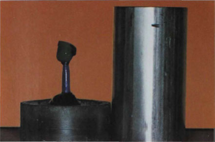
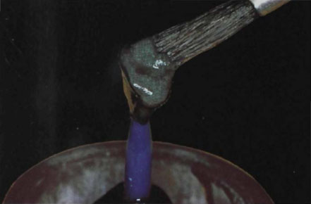
Figure 5-33a
Stay updated, free dental videos. Join our Telegram channel
VIDEdental - Online dental courses


