Fig 11.1 (A and b) Abutments of single-piece implants are prepared in the mouth. (C) Impression is made with the prepared abutment technique and sent to the dental laboratory where the technician poured the impression using high strength stone and fabricated the four-unit ceramic bridge prosthesis. (D) The prosthesis is fixed over the implants using dual cure resin cement.
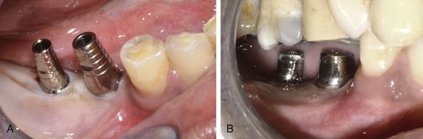
Fig 11.2 (A) The healing abutments are removed and replaced with the appropriate final abutment over the two-piece implants. (B) The abutments are prepared in the mouth using high speed turbine with carbide/diamond burs.
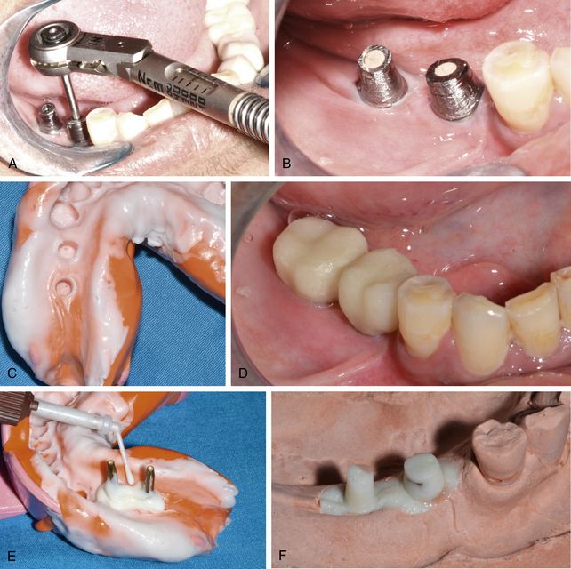
Fig 11.3 (A) The connection screw is finally tightened, using a mechanical torque ratchet, at 35 Ncm (B) the screw holes are filled using gutta-percha and (C) impression is made in silicon material. (D) A provisional prosthesis in function is fixed over the abutments which also avoids oral soft tissue abrasions with the abutment. (E) The abutment region of the impression is poured using the high strength core build-up material or pattern resin with dia pins inserted into it. (F) The impression is further poured with dia stone and a working cast is prepared.
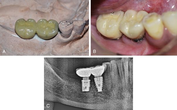
Fig 11.4 (A) A PFM prosthesis is fabricated over the cast, (B) which is transferred and fixed over the implant abutments in the mouth following normal crown and bridge technique. (C) Post loading radiograph.
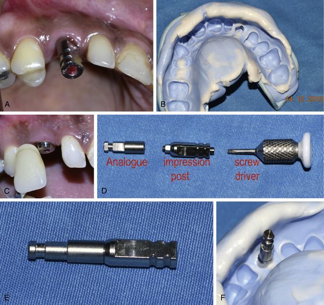
Fig 11.6 (A) The impression post for closed tray impression technique is inserted over the implant and (B) the impression is made in addition silicon material. (C) The impression post is again replaced with gingival former over the implant and shade selection is done. (D and e) The impression post is assembled with an appropriate implant analogue using a screwdriver and (F) inserted into the impression with the same orientation as in the mouth.
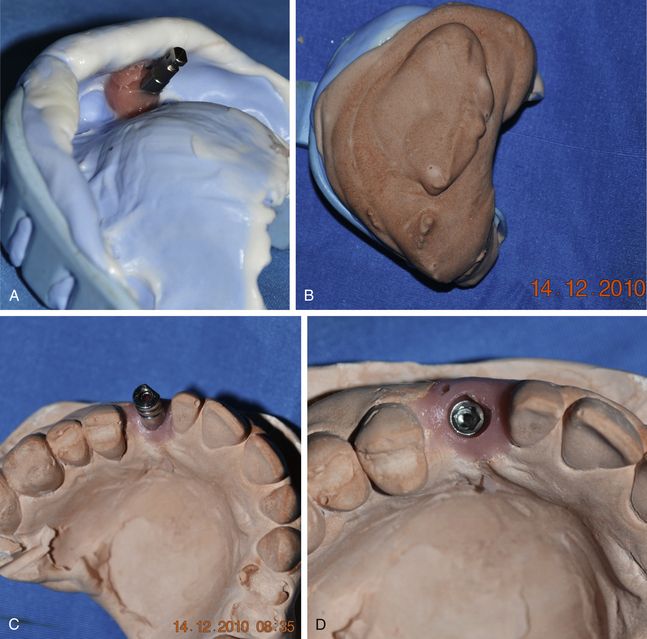
Fig 11.7 (A) A soft tissue masking material (Gi-Mask, Coltene Whaledent or Multisil, Bredent) is poured around the impression post to the level of post–analogue connection. (B) The impression is poured further using the stone. (C and d) The impression post, which accurately has transferred the position and orientation of implant connection from the patient’s mouth to the working cast, is removed from the analogue.
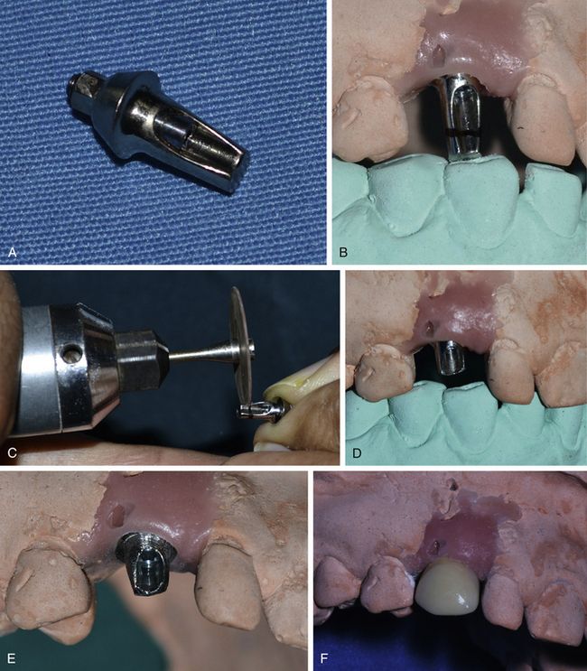
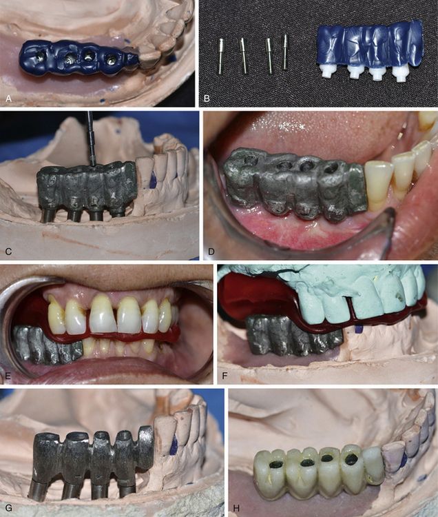
Fig 11.8 (A) An appropriate final abutment is selected and (B) fixed over the analogue. (C and d) The height of the abutment is marked and reduced. (E) The abutment is further prepared like a normal crown abutment preparation. For the abutment cutting and preparation, it should be removed from the analogue and assembled with another analogue because vibration can loosen the analogue within the stone cast. (F) A ceramic prosthesis is fabricated over the abutment.
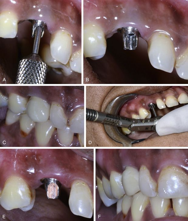
Fig 11.9 (A and b) The abutment is transferred to the implant with correct orientation and (C) the try-in of the prosthesis is done to check for its fitting. All the required occlusal adjustments are done. (D) The connection screw is finally tightened at 35 Ncm using a torque ratchet. (E) The screw hole is filled using warm gutta-percha and (F) the prosthesis is fixed over the abutment using glass ionomer luting cement.
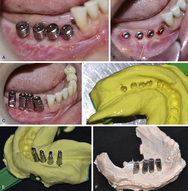
Fig 11.10 (A and b) Gingival formers (healing abutments) are removed from the implants and (C) the closed tray impression posts are inserted. (D) A closed tray impression is made and (E) the posts assembled with implant analogues are inserted into the impression with correct position and (F) orientation to prepare a stone cast.
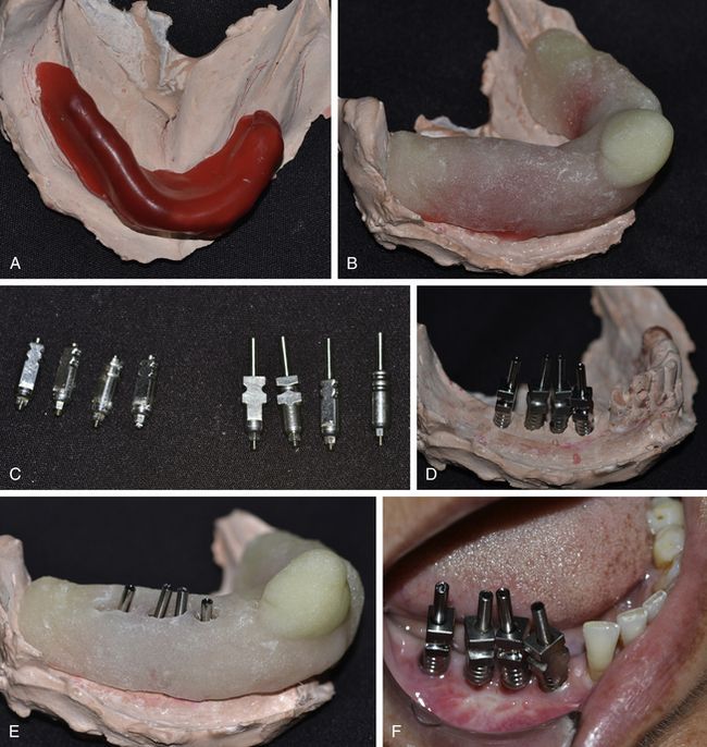
Fig 11.11 (A) Wax is used as the spacer and to block the undercuts, and (B) a special tray is fabricated over the cast. (C and d) The closed tray impression posts are removed from the cast and replaced with the open tray impression posts. (E) The spacer is removed from the special tray and holes are prepared over the implant sites, so that the long connection screws of the impression posts emerge out and above the impression tray. (F) The open tray impression posts are inserted over the implants in the patient’s mouth.
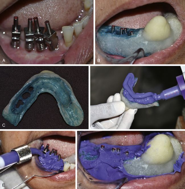
Fig 11.12 (A) The screw holes are blocked using wax and (B) try-in, for complete and passive seating of the special tray, is done. (C) A tray adhesive should be used on the inner surface and edges of the tray. (D–F) The impression is made using polyether (3M ESPE, Impregum Penta) impression material with the post screws emerging out and above the impression.
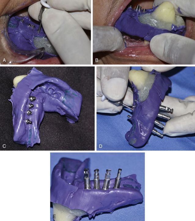
Fig 11.13 (A) All the connection screws should be unscrewed from the implants, (B) before removing the impression from the patient’s mouth. (C) On removing the impression from the patient’s mouth, the open tray posts come out firmly engaged within the impression. (D and e) The analogues are assembled with the posts and connection screws are tightened.
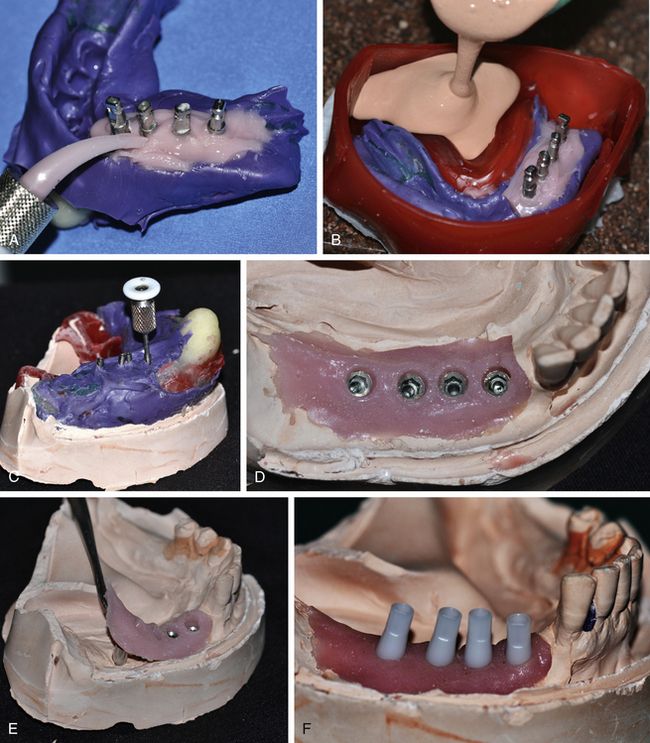
Fig 11.14 (A) First, a soft tissue replicating material (Multisil Mask, Bredent, Germany) should be poured around the post analogue connections in the impression (B) followed by the pouring of the impression using high strength stone material. (C and d) Again the post screws should be unscrewed from the analogues before removing the impression from the cast. (E) Use of soft tissue replicating material has the advantages of easy removal of the posts from the analogues without cast material fracture, easy visualization and working at the analogue platform by the laboratory technician as this material can be removed and replaced as many time as required without any distortion. (F) The appropriate castable plastic abutments are inserted over the analogues and fixed using titanium connection screws.
Stay updated, free dental videos. Join our Telegram channel
VIDEdental - Online dental courses


