Fig 15.1 (A) Pikos block grafting bur kit. (B) Oscillating saw for bone harvesting. (C) Reciprocating saw for bone harvesting.
(Courtesy: Salvin Dental Specialties, USA).
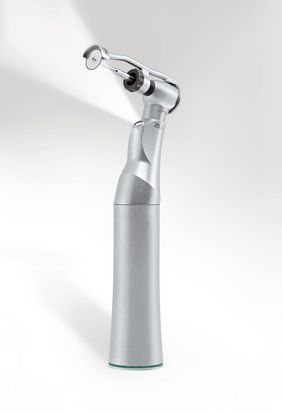
Fig 15.2 Frios Microsaw (Dentsply Friadent) is a very useful tool for intraoral corticocancellous block harvesting. Its 0.25 mm diamond disc allows precise preparation of donor sites. Its tissue guard controls depth of osteotomy and protects the soft tissue from injury. Its conservative axis minimizes surgical trauma. The horizontal cuts made using contra-angle and vertical curves are made using a straight handpiece.
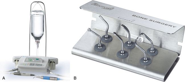
Fig 15.3 (A and B) Piezotome with bone surgery kit. Bone surgery kit comprising six ultrasonic tips (three saws and three scalpels) adapted to the different cases that arise in the intraoral environment, used for clinical treatments such as bone harvesting, osteoplasty, crest expansion, preparation of the implant site, accessing the lower alveolar nerve, etc. The use of the piezosurgery unit offers many advantages such as fast, fine, and selective cut (cuts only bone without any injury to the soft tissue), and fast healing.
(Courtesy: Setlec, France).
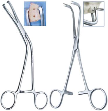
Fig 15.4 Anterior and posterior cortical block clamps with slotted tips.
(Courtesy: Salvin Dental Specialties, USA).
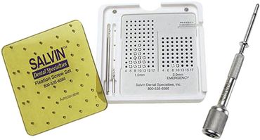
Fig 15.5 Bone blocks fixation system containing drills, mini screws and screwdriver. Usually 1.5 or 2.0 mm diameter screws are used, which can be 6–18 mm long.
(Courtesy: Salvin Dental Specialties, USA).
Step by step surgical technique
Step 1: A mucoperiosteal flap is elevated to expose the host site.
Step 2: A small round or straight fissure carbide bur is used to create inlay preparation and to make the small perforations through the cortex at the host site. This enhances the blood supply to the bone block from the underlying spongiosa of the host site.
Step 3: The mucoperiosteal flap is elevated to expose the donor site and a bone block of the desired shape, but 1–1.5 mm smaller in size than the prepared recipient site, is harvested.
Step 4: Block graft should be stored in blood, saline, or nonactivated platelet-rich plasma.
Step 5: A small amount of additional autogenous bone can also be scraped out from the donor site and stored in blood, saline, or nonactivated platelet-rich plasma.
Step 6: The block graft is tried over the prepared recipient site for its intimate adaptation. The further preparation of the recipient site, if required, is preferred over the shaping of the block graft.
Step 7: Two to three holes are prepared through the block graft for the fixation screws, using a straight carbide bur.
Step 8: The block graft is transported to the recipient site, adapted at the desired three-dimensional positions (preferably the cancellous face of the block towards the host bone), and the holes in the block are extended into the host site to the desired depth, using the same straight fissure bur. At the time of extending the holes through the block, the block is held at the position using the block-holding forceps. Further, the block is immobilized at the recipient site using two to three fixation screws.
Step 9: The particulated autogenous bone that has been harvested from the donor site, is mixed with synthetic or xenograft (Bio-Oss) and delivered at the host site to fill the deficiencies around the bone block.
Step 10: A barrier membrane can be used to cover the whole grafted site. The surgeon can avoid the barrier membrane in selective cases, because the cortical part of the block graft itself prevents the soft tissue creeping into the grafted region. The barrier membrane should be used, if a large region around the block is grafted using particulate graft.
Step 11: Verify the passive flap closer over the grafted site and if required, the flap is released and coronally advanced to cover the grafted site for a watertight primary closure.
Step 12: The site is left to heal for 4–6 months without any functional loading over the grafted site (no softtissue-supported prosthesis should be used). The site is uncovered after the graft has united with the host bone, with the phases of resorption and apposition at the graft and host bone interfaces. This process may however take 4–6 months. The fixation screws are removed and implants are inserted in the consolidated new bone.

CASE REPORT-1
Step by step clinical presentation of block grafting using autogenous block from the mandibular ramus buccal shelf(< ?xml:namespace prefix = "mbp" />
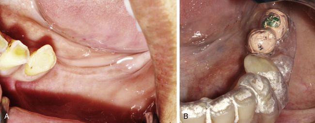
Fig 15.6 Clinical view of the edentulous ridge of missing molars. (A) Patient was seeking implant-supported fixed prosthesis. (B) A radiographic template is fabricated to plan the appropriate positions for implant placement at molar sites.
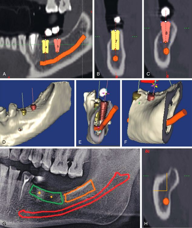
Fig 15.7 (A–F) When two regular diameter implants were planned to replace the teeth no. 46 and 47 using CT planning software, the various CT views showed the deficient buccolingual bone dimensions at the crestal part of the ridge. The block grafting was planned to reconstruct the lost bone dimensions. (G and H) The ramus buccal shelf area was chosen as the donor site.
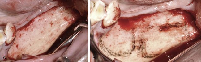
Fig 15.8 (A) A mid-crestal incision was given and the mucoperiosteal flap was elevated to expose the recipient as well as the donor sites. (B) The host and donor sites were separately marked using a sterile HB pencil.
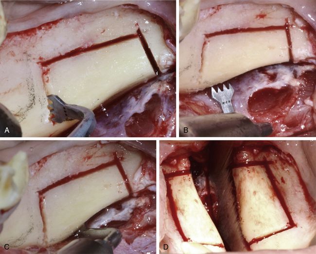
Fig 15.9 (A–D) The different types of Piezotome bone surgery saws were used to prepare a rectangular osteotomy at the ramus buccal shelf area under copious chilled saline irrigation. Care should be taken to avoid any injury to the inferior alveolar nerve. The osteotomy preparation should be done minimally to reach the underlying spongiosa. By completely bypassing the high density cortex all around, it is easy to separate the block from the site.
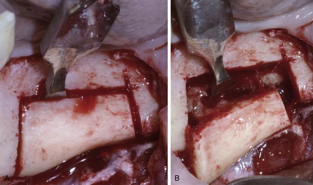
Fig 15.10 (A and B) Once the rectangular osteotomy is completed deep enough to reach the underlying cancellous bone, bone chisels or osseous splitters are used to laterally separate the bone block.
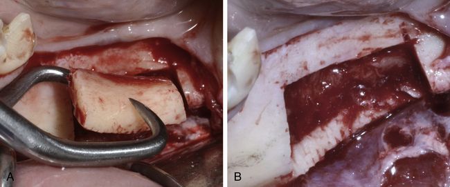
Fig 15.11 (A) Block-holding forceps can be used to hold the block. (B) Donor site as seen after the block removal. If the mandibular nerve comes out attached to the inner surface of the block, it should be carefully detached using any blunt instrument before removing the block from the site.
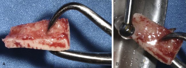
Fig 15.12 (A) The block harvested from the mandibular ramus buccal shelf mostly contains the cortical bone with very little or no cancellous bone. (B) As and if required, the block is shaped using a large round carbide bur to fit the host site. All the sharp edges of the block should be smoothened for easy and effective adaptation of the overlying soft tissue without any perforation or tearing.
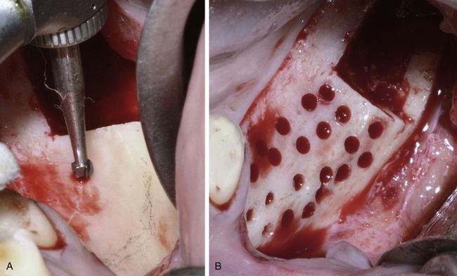
Fig 15.13 (A and B) A small round carbide bur is used to prepare multiple holes through the cortex at the host site to receive the nutrient blood supply from the host bone to nourish and keep alive the transplanted autogenous block graft cells.
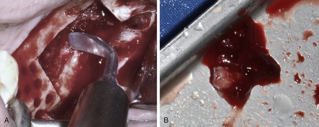
Fig 15.14 (A and B) A small amount of cancellous bone can be scraped out from the donor site using a piezotome bone scraper.
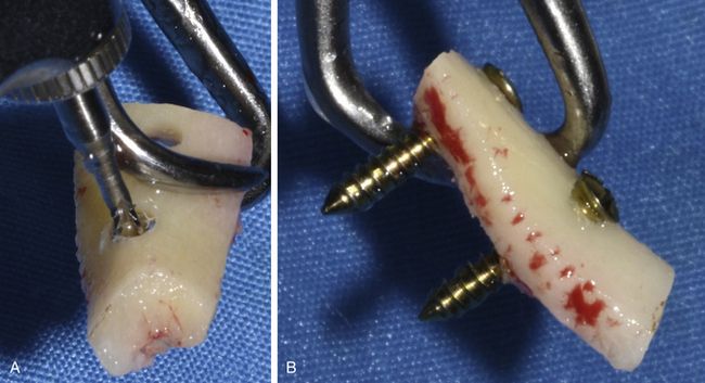
Fig 15.15 (A and B) Two holes are prepared through the block using a long carbide bur and two block fixation screws are inserted.
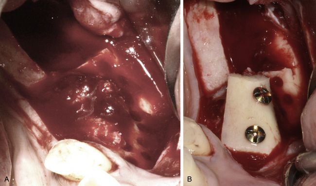
Fig 15.16 (A) The cancellous bone is delivered at the host site to fill the gaps between the inner surface of the block and the host bone. (B) Now the block is placed over the host site and firmly immobilized using fixation screws.
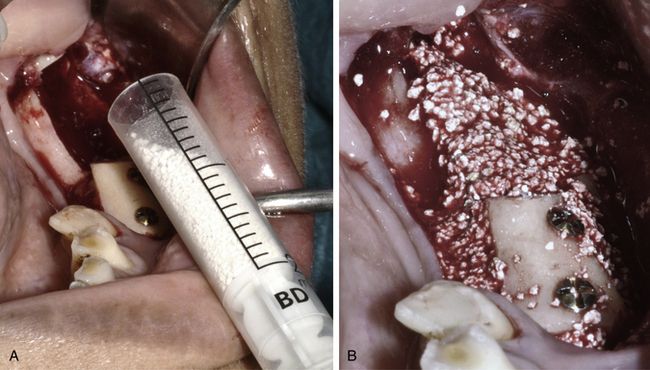
Fig 15.17 (A and B) The particulate graft (HA + β-TCP) is used to fill the spaces and deficiencies around the bone block as well as to fill the donor site.
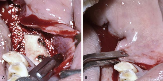
Fig 15.18 (A and B) Horizontal releasing incisions are given through the periosteum underneath the facial flap to release it for coronal advancement and to achieve tension-free primary closure.
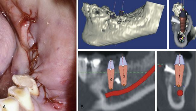
Fig 15.19 (A) The flap is sutured to achieve a watertight closure. (B) The dental CT 4 months after block grafting, showing newly regenerated bone dimensions, which are now adequate for regular to wider diameter implant placement.
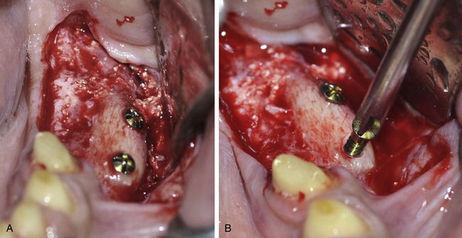
Fig 15.20 (A and B) The mucoperiosteal flap is elevated to expose the grafted site and the fixation screws are removed using screwdriver. The block as well as the particulate graft has been consolidated and the site is ready to receive the implants.
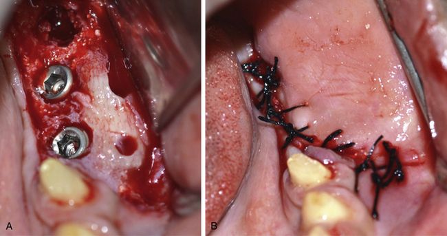
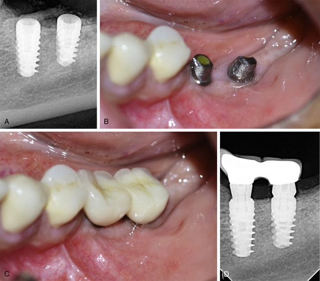
Fig 15.21 (A and B) Two wider diameter implants (5 x 10 and 6 x 10 mm) are inserted at the ideal prosthetic positions and flap is sutured back for submerged healing of the implants.
Stay updated, free dental videos. Join our Telegram channel
VIDEdental - Online dental courses


