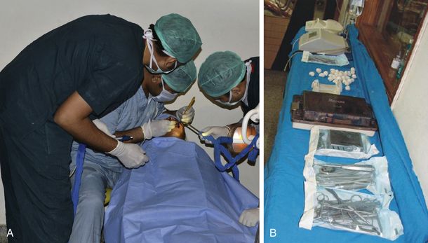
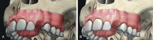
A. Incision The type of incision and extent of flap elevation depend on several factors such as the width of the attached keratinized tissue, ridge form, presence of any undercut, any other simultaneous grafting procedure to be done, etc. Usually a mid-crestal incision is given with or without vertical incisions and the flap is elevated to expose the crestal, facial, and lingual parts of the bony ridge (Fig 8.3A and B).
Key points
1.
The attached keratinised gingiva at the ridge crest should be evaluated before making the incision.
a.
If the implant site has an adequate buccolingual band of keratinized soft tissue, the incision should be made so as to bisect the keratinized soft tissue band, which results in minimum 2–3 mm keratinized soft tissue on both the labial as well as the lingual side of the implant.
b.
If the implant site has an inadequate keratinized soft tissue band, the incision should be made so as to bisect the thin keratinized soft tissue band and implants are placed and soft tissue grafting should be performed at the stage of re-exposure of the implant.
2.
If papillae are intact on the implant site, the papilla preservation incision should be preferred to maintain papillae height and to achieve better soft tissue aesthetics around the future implant prosthesis.
B. Flap elevation Facial and lingual mucoperiosteal flaps should be elevated to expose the ridge crest as well as the facial and lingual part of the ridge (Fig 8.4A and B)
Key points
1.
Both facial as well as lingual flaps are elevated to completely expose the ridge crest and buccal and lingual cortical plates in the case of compromised bone width or ridge with undercuts. This will allow three-dimensional visibility of the bony ridge during implant osteotomy preparation and avoid the chances of inadvertent perforation or dehiscence during drilling.
2.
The flaps are elevated to expose the ridge crest and facial cortical plate in case of:
a.
Compromised/limited ridge width or the ridge with facial undercut.
b.
Thin facial and thick palatal cortical plate (e.g. anterior maxilla), which causes the slipping of drills towards the thin facial plate during osteotomy preparation, and may result in dehiscence/perforation through the facial cortical plate. Thus, a direct visualization of the facial cortical plate is paramount during controlled osteotomy preparation.
3.
The flaps are minimally elevated to expose the ridge crest in the case of a wide ridge crest with stepped apical widening (e.g. posterior maxilla and posterior mandible). Whereas it has least chances of perforation, unnecessary elevation of the buccal and lingual flaps leads to reduced blood supply to the bone from the periosteum during the initial phase of healing.
C. Pilot drilling: After exposing the underlying bony ridge, either a surgical stent is seated on the site or the reference of adjacent teeth is taken to prepare the implant osteotomy, which is three-dimensionally correct for the future prosthesis (Fig 8.5A and B). A sharp pointed lance drill or pilot drill is used to make an initial entry into the bone. Alternatively, a small round bur can be used to mark the implant site and to drill through the high-density crestal bone (Fig 8.5C and D).
Key points
1.
If the ridge crest is irregular, it should be flattened using a large round carbide bur before starting pilot drilling.
2.
Before using the pilot drill one can also use a small round carbide bur to mark the osteotomy site and to punch through the hard cortex.
3.
Drilling (pilot drill to final drill) must be done at speeds of 1200–2500 rpm depending on bone density, under a constant stream of chilled saline. The torque of the implant motor should be adjusted between 30 and 50 Ncm so that the drill does not stop during osteotomy preparation, especially in hard bone.
4.
A pumping motion of the drill should be employed during drilling to allow the saline to cool down the bone. This prevents overheating and necrosis of the bone.
5.
An intraoral periapical (IOPA) radiograph can be taken at this stage to see the direction of the drill, especially in tight spaces or in the areas of vital structures like the maxillary sinus or mandibular canal. After pilot drilling to partial depth, this drill is inserted into the osteotomy, and a periapical radiograph taken to evaluate the direction of drilling and the availability of the bone dimensions for further osteotomy deepening.
D. Depth drilling: The pilot drill or depth drill which usually remain 2 mm of diameter first used to the partial depth and direction of drilling is three-dimensionally evaluated by inserting a parallel pin/force direction indicator in the partially prepared osteotomy. If the direction is correct, the depth drill is further used to the complete depth (Fig 8.6A–D). All the planned osteotomy depth should be attained by pilot drill itself as the rest of the drills are only used to widen the osteotomy. For example, if a 13 mm long implant is planned, depth drill should attain 13 mm depth in the bone before the use of osteotomy-widening drills.
Key points
During or after pilot drilling, if the dentist finds that he/she has drilled in the incorrect direction, he/she can correct the osteotomy direction to some extent by using the special side-cutting Lindemann drill (2 mm diameter)
E. Osteotomy widening: After pilot drilling to the planned depth, the osteotomy-widening drills are sequentially used to the same depth. A series of different diameter osteotomy-widening drills (e.g. 2.8, 3.2, 3.65, 4.2 mm diameters) are used to the same depth depending on the diameter of the implant (Fig 8.7A–D). Depending on the bone density, the diameter of final drill should be 0.3–0.8 mm less than the diameter of the implant (e.g. if the planned implant diameter is 5 mm, the diameter of final drill must be approximately 4.2 mm in D3/D4 bone and 4.7 mm in D1/D2 bone).
Key points
1.
For the implant with non-cutting/nonself-tapping threads, a bone tap or thread former can be used after the final drill and before inserting the implant in high-density (D1 and D2) bone. The bone tap should be used at the speed of 20–30 rpm.
2.
Crestal bone drill can be used to submerge the implant platform apical to the ridge crest, if the implant platform is wider than its body. This drill is used at the same speed as the final drill.
F. Final assessment of prepared osteotomy: After the final drill, the prepared osteotomy should be checked using a depth probe, for complete depth preparation and also to check any inadvertent perforation that has occurred through the osteotomy walls (Fig 8.8A and B).
Key points
1.
Any perforation or thinning of any cortical plate should be finally checked at this stage and if detected, the surgeon should perform bone grafting.
2.
The osteotomy site should be irrigated using chilled sterile saline to remove all the residual bone debris which can get collected at the apex and prevent the complete setting of the implant.
3.
After irrigating the prepared osteotomy with saline, do not suck the site but let the fresh blood oozing out from within the prepared osteotomy, before inserting the implant. If it is not seen, the surgeon can provoke bleeding by inserting any tool in the prepared osteotomy. For early and predictable osseointegration, the osteotomy should remain filled with fresh blood during implant insertion, for clot formation between the implant surface and osteotomy walls.
G. Opening the implant packaging: The implant being highly sterile, remains packed in a sterile vial which is further packed in an outer non-sterile packing. The outer non-sterile covering of the implant vial should be opened by the assistant without touching the inner sterile vial, which contains the implant and cover screw (Fig 8.9A and B). The implant surgeon wearing sterile gloves should open this inner vial to take the implant out from it.
H. Taking out the implant from its vial and carrying it to the prepared osteotomy: After the surgeon has opened the inner sterile vial containing implant and cover screw, the implant driver is engaged into the implant connection, the implant is removed from its vial, and carried to the prepared osteotomy without touching its surface (Fig 8.10A–D). An implant mount comes connected into the implant connection in a few systems. This implant mount is used to remove the implant from its vial and to carry it to the osteotomy by hand/hand ratchet adaptor/rotary handpiece adaptor.
I. Implant insertion: The implant is carried to the prepared osteotomy and screwed in with clockwise rotations at very slow speed (30–40 rpm) using a rotary handpiece or hand ratchet (Fig 8.11A and B).
Key Points
1.
If surgeon feels a little resistance, he/she should stop inserting the implant and wait for a moment. He/she should let the surrounding bone expand and then restart rotating and inserting implant. This can be done several times till all the implant gets completely seated into the osteotomy.
2.
If surgeon feels greater resistance he/she should stop inserting the implant, rotate it counter clockwise to unscrew 2–3 threads of the implant
to release the pressure on the bone, wait for a moment to let the surrounding bone expand and then restart rotating and inserting the implant. This can be done several times until all the implant gets completely seated into the osteotomy.
3.
If implant is not going in by following the abovementioned two protocols or exerting a greater moment force (more than 40–50 Ncm) on the surrounding bone, then it can cause pressure necrosis of the surrounding bone. Unscrew the implant and remove it from the osteotomy site and transfer it to its sterile vial. Further widen the osteotomy by using the next diameter drill and reinsert the implant.
4.
All the implant threads should get submerged into the bone. If any bone defect exists, it can lead to exposure of implant threads. These exposed threads should be covered using bone graft before closing the flap.
5.
The complete seating of the implant should present the implant platform flush with the ridge crest in D1, D2, and D3 bone. The implant platform can be submerged 0.5–1 mm apical to the ridge crest in D4 bone, to avoid any premature loading of the implant which may cause micro movement of the implant during its healing phase and may lead to fail to osseointegrate.
6.
While inserting the implant in aesthetic regions, the platform of the finally seated implant platform should be 2 mm apical to the cementoenamel junction (CEJ) of adjacent teeth or their gingival zenith, to achieve an acceptable soft tissue emergence around the implant prosthesis. The implant platform should also be placed 2 mm palatal to the imaginary line or straight probe meeting the facial aspects of the CEJ of the two adjacent teeth.
J. Cover screw insertion and flap suturing: Following implant insertion, the implant driver is removed from the implant connection, and the cover screw is removed from the implant vial and screwed over the implant connection using a screwdriver. After inserting cover screw, the flap is sutured back with a tension-free primary closure (Fig 8.12A–F).
Key points
1.
An antibacterial repellent jelly like Terramycine ointment or Metrohex ointment can be applied over the threads of cover screw before inserting it over the implant, to prevent any microbial growth into the implant connection during its healing phase.
2.
The cover screw should not be tightened with great moment force, because this can present problems at removal on uncovery. If it is tightened at a high torque, often the implant itself comes out connected to the cover screw, especially in low-density D4 bone.
3.
If the implant surgeon decides on a non-submerged implant healing protocol, a long gingival former can be inserted directly over the implant in spite of using cover screw, and the flap can be sutured around it.
4.
Tension-free sutures should be used to avoid the suture line opening because of the tension in the flap.
5.
If achieving primary closure becomes difficult, as in cases of implant insertion with simultaneous bone grafting, the flap should be released by making horizontal releasing incisions through the periosteum from underneath the flap. A 3-0/4-0 non-resorbable Ethicon or a resorbable chromic gut suture can be used for the suturing.
6.
The sutured tissue surface should be cleaned using chlorhexidine and a light pressure pack of moistened cotton is given. The patient is instructed to keep the mouth closed for 1 h.
7.
An ice pack is given to the patient to apply over the facial skin of the surgical site intermittently for 45 min to cool down the bone. The application of a cold pack is beneficial for 48 h after surgery to suppress heat generation and inflammatory oedema, which leads to tension in the soft tissue resulting in suture line opening. Hot fomentations are beneficial after 48 h to diffuse the inflammatory fluid from the site, which reduces soft tissue oedema.
8.
If not given before surgery, an intramuscular injection of a potent pain killer like tramadol or diclofenac and a steroid like dexamethasone, can be given after the surgery to reduce the chances of postoperative pain and swelling.
9.
Antibacterials like the amoxicillin and clavulanate combination (tab. Augmentin 1 g b.i.d.), analgesics
like the aceclofenac, paracetamol and serratiopeptidase combination (tab. Hifenac-D, b.i.d.) and multivitamins (cap. Becosule, o.d.) are prescribed for a minimum of 5–7 days.
10.
The patient is instructed to take only soft foods for a minimum of 24 h and to avoid any hot and spicy food. The patient should also be instructed to avoid pulling the lip and checking the surgical site, which can result in suture line opening.
11.
Patient should be instructed to brush his/her teeth and rinse the mouth 3–4 times a day and after every meal, with 0.12% chlorhexidine (Periogard) to maintain oral hygiene after surgery (after the flap get stabilized).
12.
If possible, the patient should be recalled for a follow-up check the day after the surgery.
13.
Sutures should be removed after 7–10 days.
K. Implant uncovery: Once the implant gets osseointegrated with the bone, the implant is uncovered by making a small crestal incision or using the tissue punch. The cover screw is removed and replaced with a long gingival former/healing abutment/permucosal extension (Fig 8.13A–D).
Key points
1.
If adequate width of keratinized soft tissue collar is present on the implant site, the implant can be uncovered by using a soft tissue punch.
2.
Gingival formers are available in different heights, thus one with the correct height should be chosen, depending on the soft tissue thickness over the implant.
3.
A custom-made gingival former (provisional crown fabricated over a temporary abutment) can also be used to create a ‘C’ shaped aesthetic soft tissue collar around the future implant prosthesis in an aesthetic region (
Fig 8.14A–C).
L. Making implant impression: After the soft tissue around the gingival former has healed, the gingival former is removed and an impression post is screwed over the implant. An impression is made in polyether or additional silicon material (Fig 8.15A–D). After removing the impression from mouth, the impression post is removed from the implant and the gingival former is reinserted. The patient is sent back after shade selection and bite registration (Fig 8.15E–H).
Key points
1.
The complete seating of the impression post over the implant should be checked with a radiograph before making the impression, because the impression of an incompletely seated impression post can result in incorrect transfer of implant orientation and subsequent inaccurate seating of the final prosthesis.
2.
The impression should be made with open tray technique, using a long open tray impression post if the implant is deeply seated in the soft tissue. If the closed tray impression post emerging out of the soft tissue is very short, it may not get properly engaged in the closed tray impression, thus leading to inaccurate transfer of the implant hex position. The open tray posts should also be preferred in multiple implants or full-arch cases, for precision in the fit of the multiunit prosthesis over implants.
3.
Screw hole of the impression post should be blocked using wax before making the impression, as it can hinder the reseating of the post into the impression.
4.
Usually, the impression post has one long flat side which guides the implant dentist in transferring this post from the implant to the impression with the correct orientation.
M. Pouring the implant impression: The impression post which is removed from the mouth is assembled with the implant analogue which has different body, but the connection is exactly similar to the implant. Further, the post assembled with the analogue is reseated into the impression at the same position and with same orientation (Fig 8.16A–C). The soft tissue replicating material (Multisilk, from Bredent, Germany) is poured around the post-analogue connection (Fig 8.16D), followed by pouring of the impression with high-strength stone plaster (Fig 8.16E). The stone cast is removed from the impression after it has set. The stone cast will contain the analogue inside the stone with impression post emerging out of it and soft tissue replica around it (Fig 8.16F). The impression post is removed from the analogue (Fig 8.16G). Now the implant connection position and orientation have been transferred exactly from the mouth to the cast (Fig 8.16H). The soft tissue replica can be removed and reseated as many times as required, without any distortion to visualize and to work on analogue abutment connection.
N. Fabrication of the final prosthesis: The final abutment of choice is screwed over the analogue and shaped/milled using carbide/diamond bur for the fabrication of the final prosthesis. A desired final prosthesis is fabricated over this abutment (Fig 8.17A–D).
Key points
1.
At this step, the implant dentist and laboratory technician can decide to fabricate either a cement or screw retained prosthesis of choice. For cement-retained prosthesis fabrication, the technician fixes an appropriate metal abutment over the analogue and shapes it to a desired shape. Further, the technician fabricates the prosthesis over it similar to normal crown fabrication onto the reduced natural tooth abutment. For screw-retained prosthesis fabrication, a plastic castable abutment is fixed onto the analogue, shaped and sent to the dental laboratory. The dental technician makes a wax pattern of the coping over this plastic abutment, removes it from the analogue and after removing its connection screw, he/she casts all together to fabricate a metal coping that can be fixed directly over the analogue using the connection screw. Further, the ceramist builds the ceramic over this casting keeping the patency of fixation screw opening. This screw retained ceramic prosthesis dentist directly fix to the implant in the mouth using connection screw.
2.
If the implant placement is not prosthetically guided or if the implant surgeon has intentionally inserted the implant at an angle to the long axis of the prosthesis to insert it in best available bone, one can use an angled abutment to fabricate the prosthesis at the correct axis. The 15–25° angled abutments (metal as well as plastic) are available in most implant systems to correct this prosthetic problem.
O. Fixing the final prosthesis over the implant: The dentist receives either the cement-retained or screw-retained prosthesis from the dental laboratory which he/she needs to finally fix onto the implant in the mouth.
1.
Fixing the cement-retained prosthesis: The dentist receives a dental cast from the dental laboratory, which contains the implant analogue connected to metal abutment and the prosthesis over the abutment. The prosthesis from the abutment is removed and the abutment is marked on the facial side using a permanent ink marker and the same is extended to the cast so that one can correlate the same orientation to the abutment in the patient’s mouth. The gingival former from the patient’s mouth is removed and the abutment is transferred from the cast to the implant in the patient’s mouth with the same orientation. The prosthesis is seated onto the abutment and checked for fitting. One should check the complete seating of the prosthesis with a radiograph. After all the required occlusal adjustment has been done, a mechanical screwdriver (torque ratchet) is used to finally tighten the implant abutment connection screw at the moment force of 30–35 Ncm to avoid any future screw loosening problem under the prosthesis. The screw hole is filled using hot gutta-percha or wax and the prosthesis is fixed using zinc oxide eugenol/zinc phosphate/glass ionomer luting cement (
Fig 8.18A–F).
2.
Fixing the screw-retained prosthesis: The dentist receives from the dental laboratory, the dental cast with implant analogue connected to the prosthesis by a connection screw through a screw hole in the prosthesis. The gingival former is removed from the patient’s mouth and the prosthesis is transferred to the implant in the patient’s mouth with the correct orientation, and screwed in using the connection screw. The complete seating of the prosthesis is radiographically checked. All the required adjustments are done and a mechanical screwdriver (torque ratchet) is used to finally tighten the connection screw at the moment force 30–35 Ncm. The screw hole is first filled with the hot gutta-percha followed by light cure composite over it to blend its shade to the shade of the prosthesis (
Fig 8.19A–H).