Cone-beam computed tomography (CBCT) has become popular, and its many inherent advantages are indisputable. Nevertheless, CBCT is prescribed cautiously because the radiation dosage is higher than that of conventional radiography. When and to what extent should CBCT be prescribed for orthodontic patients? The purpose of this article is to present 4 curious cases in which a considerable discrepancy was found between the conventional panoramic radiograph and the CBCT view. Is it time to spare patients an unnecessary conventional panoramic radiograph and shift to CBCT for all patients?
Cone-beam computed tomography (CBCT) is becoming increasingly popular; its advantages include a variable field of view, voxel isotropy, 3-dimensional (3D) localization, accuracy, variable slice-thickness viewing, multiplanar reformatting (MPR), 1:1 life-sized image analysis, and high spatial submillimeter resolution with a low radiation dose. Abnormalities that are more accurately identified with CBCT include impacted teeth and root resorption. However, CBCT scans are not as widely prescribed as their advantages might suggest. The discrepancy can be ascribed to the comparatively high radiation dose compared with conventional radiography. However, proper exploration of the advantages of CBCT might promote its prescription. When and to what extent should we prescribe CBCT? In this article, we present 4 unusual cases in which a considerable discrepancy was found between the conventional panoramic radiograph and the CBCT view.
Material and methods
Case 1
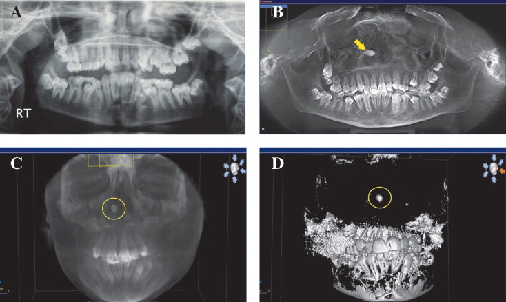
A 14-year-old girl sought orthodontic treatment at our office at Cairo University, Cairo, Egypt. The conventional panoramic radiograph ( Fig 1, A ) showed no apparent abnormality. We took a CBCT scan as part of our routine orthodontic records. The MPR tool was used to generate a panoramic view from the CBCT, and it, surprisingly, showed a radiopaque structure in the nasal region ( Fig 1, B ). Initially, we suspected it was an artifact, but it was also visible on the 3D volume rendering ( Fig 1, C ). After adjusting the threshold and subtracting the surrounding bone on the 3D surface rendering, the structure maintained its radiopacity and resembled an ectopic tooth crown-like structure ( Fig 1, D ). The ear, nose, and throat specialist’s differential diagnosis was either a tooth crown, a rhinolith, or a foreign body. Ultimately, it was aspirated and found to be a pencil eraser.

Case 2
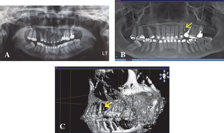
A 32-year-old woman who had started orthodontic treatment elsewhere came to Cairo University because she was dissatisfied with her treatment and especially her clinician’s inability to upright her maxillary left molar. Her conventional panoramic radiograph ( Fig 2, A ) showed no obvious explanation for the delayed uprighting. However, the panoramic view generated from CBCT ( Fig 2, B ) and the 3D volume rendering ( Fig 2, C ) showed a well-defined root remaining in the maxillary left second premolar region.

Case 3
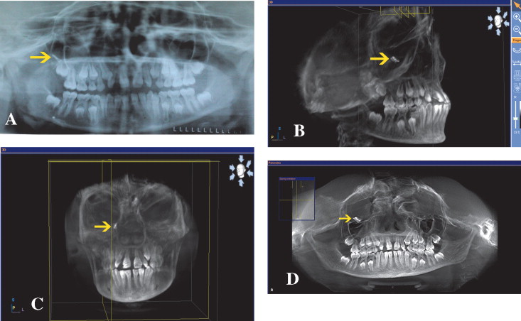
A patient with a dislodged temporary anchorage device (TAD) in the right maxillary sinus was referred for examination. A conventional panoramic radiograph was prescribed by the orthodontist to locate the device ( Fig 3, A ). The surgeon requested a 3D view ( Fig 3, B and C ). A large discrepancy in the spatial position of the TAD was apparent between the conventional panoramic radiograph and the panoramic-derived view ( Fig 3, D ).

Case 4
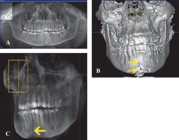
A patient with a temporomandibular joint disorder was treated by her dentist with a temporomandibular joint splint. She spent much time in treatment with no amelioration of the symptoms. At the dentist’s request, a CBCT scan was done for further investigation. The panoramic view generated from the CBCT scan showed no abnormalities ( Fig 4, A ). However, the 3D surface rendering showed a curious finding: a line resembling an unhealed fracture in the symphyseal region extending from the inferior border of the mandible and approaching the alveolar margin in the 3D view, but it was invisible in the panoramic view of the CBCT ( Fig 4, C ).

Discussion
When a panoramic radiograph reveals a potential risk for the patient, 3D views are often recommended for further investigation. However, panoramic radiographs can fail to show risks that are actually present. Studies investigating the efficiency of panoramic radiographs showed that they have an image distortion rate of about 20% compared with the patient’s true anatomy. Bell et al reported that the sensitivity and specificity of panoramic images were 66% and 74% on average, respectively. Moreover, when the quality of panoramic radiographs was assessed, the results showed that only 0.8% of the images were excellent, 66.2% were diagnostically acceptable, and 33% were unacceptable; the most common faults were positioning errors, low density, and contrast.
Three-dimensional images are becoming more readily available and an important tool for clinical applications in orthodontic practice. Because 3D CBCT images are life-sized representations of the anatomic truth, and hence the gold standard, they might provide a solution for the panoramic incompetencies.
The pulsed x-ray exposure in CBCT minimizes the distortion in traditional panoramic imaging, which uses continuous exposure. The proprietary reconstruction algorithm calculates the 3D image of the original object from the snapshot images. Reformatting of the primary reconstruction allows for both 3D and 2D images of any selected plane. A panoramic view can be constructed with the advantages that the focal trough path defined by the user on the axial view and the layer thickness are selectable and constant, resulting in an image with no redundant shadows or artefacts.
Based on the described superiority of the CBCT imaging technique to conventional panoramic radiographs, explanations of these 4 curious findings can be formulated.
In the first case, there was a foreign body in the nasal cavity. The discrepancy between the conventional panoramic radiograph and the panoramic view generated from the CBCT was great. One possible explanation was that all data representing the buccolingual width of the face were compiled to generate the conventional panoramic view. This has the inherent potential of obscuring some structures because of the great degree of superimposition. Additionally, radiopaque objects out of the image layer superimpose on the image of normal anatomic structures. This results when the x-ray beam projects through a dense object that is in the path of the beam but out of the portion of the focal trough being imaged. These objects typically appear blurred. On the contrary, the panoramic view generated from the CBCT (MPR) has a variable slice-thickness viewing option (ray-sum). The number of layers used to generatethe CBCT panoramic view is adjustable. Minimizing the panoramic view to a limited thickness eliminates therisk of superimposition from other craniofacial structures far from the teeth.
In the second case, a root remained in the maxillary premolar area. The inefficiency of the conventional panoramic radiograph to show that root stems from the technique of linear tomographic imaging, which results in overlap of teeth. As an inherent problem in conventional panoramic images, the proximal surfaces of the premolars often overlap, and this can obscure other structures. The imaging modality of CBCT eliminates this overlap, in addition to the manipulation of the threshold for optimum visualization of the structure under study. The disagreement between the 2 imaging modalities questions the reliability of the conventional panoramic radiograph.
In the third case, there was a TAD in the maxillary sinus. Iatrogenicities associated with TADs have been recorded in the orthodontic literature. In conventional panoramic radiography, objects that do not lie in the center of rotation, out of the focal trough, move relative to the x-ray beam so that their images slide from one side to another on the film and can appear smeared on the radiograph. This results in incorrect spatial positioning of the object of interest, in addition to a blurred image. The CBCT 3D visualization gave a true representation of the TAD’s spatial position. This inherent discrepancy discredits the validity of conventional panoramicradiographs.
In the fourth case, the patient had a fracture in the midline of the mandible. Special attention must be paid to detect lesions in the midline of the mandible in panoramic radiographs because many factors can affect the appearance of this area. As a general rule, if the patient is positioned slightly lingually to the focal trough toward the x-ray source, the beam passes more slowly through it than the speed at which the receptor moves. Consequently, the images of the structures in this region are elongated horizontally on the final image. Alternatively, if the patient is positioned slightly buccally to the focal trough toward the x-ray source, the beam passes more rapidly through it than the speed at which the receptor moves, and structures appear compressed horizontally. The midline region is more radiopaque because of the mental protuberance, increased trabecular numbers, and attenuation of the beam as it passes through the cervical spine. Submandibular and sublingual depressions on the lingual surfaces of the mandible often appear more radiolucent. All these factors cause distortion of the anterior region geometrically and visually and make the diagnosis of a fracture line without displacement difficult. The crack under investigation could be a greenstick fracture or the result of an old blow to the chin. Could an old blow to the chin cause the temporomandibular joint disorder?
The findings of these 4 patients were presented in a logical sequence. This sequence rationally discredits conventional panoramic radiographs (cases 1 and 2) and credits the CBCT-generated panoramic view (case3) and the 3D views for the diagnosis of surface risks and the spatial localization of structures (cases 1–4). Hence, the argument regarding the routine prescription of CBCT should be reconsidered with rephrased questions. Do the potential limitations of conventional panoramic radiographs with obscured details call for abandoning their prescription? Is it time to spare the patient an unnecessary dosage of conventional panoramic radiography and shift to a single step of efficient data acquisition via CBCT?
Stay updated, free dental videos. Join our Telegram channel

VIDEdental - Online dental courses


