Introduction
In this study, we evaluated the accuracy and reliability of tooth-length and root-length measurements derived from cone-beam computed tomography (CBCT) volumetric data.
Methods
CBCT scans were made of 7 fresh porcine heads. The scans were made with an i-CAT machine (Imaging Sciences International, Hatfield, Pa) at 0.2, 0.3, and 0.4 mm voxel sizes. Two film-acquired periapical radiographs were also taken of selected incisors and premolars, 52 of which (28 premolars, 24 incisors) were included in this study. By using Dolphin imaging software (version 10.5, Dolphin Imaging Systems, Chatsworth, Calif), the CBCT scans were oriented twice for each tooth (ie, 2 trials) using the mesial, distal, labial, and lingual cementoenamel junctions as reference points. Root and tooth lengths were derived from these points and compared with actual measurements of the teeth made with digital calipers after all surrounding bone had been carefully removed.
Results
CBCT tooth-length and root-length measurements were not significantly different from the actual lengths; the mean differences were less than 0.3 mm. The periapical measurements significantly ( P = 0.001) underestimated root lengths (mean difference, 2.58 mm) and overestimated tooth lengths (mean difference, 2.58 mm; P = 0.056). Mean differences between the 3 CBCT voxel sizes were all less than 0.25 mm. Within-trial method errors were almost 2 times greater for the periapical radiographs than for the CBCT scans. Between-trial method errors were greatest for the 0.4-mm CBCT scans, which were within 0.1 mm of the periapical radiograph method errors. The intraclass correlations for the periapical and CBCT measurements were all above 0.995.
Conclusions
CBCT scans are at least as accurate and reliable as periapical radiographs for tooth-length and root-length determinations.
One of the greatest concerns during orthodontic treatment is the undesirable loss of root structure (ie, root resorption). It has been reported that the anterior maxillary teeth resorb an average of 1.4 mm 1 during orthodontic treatment, and that 20% of patients have at least 1 maxillary incisor resorb more that 2 mm during the first year of treatment. Orthodontically induced root resorption is also common in posterior teeth, with up to 47% experiencing some root blunting, up to 27% having moderate root resorption, and up to 6.5% with severe resorption of at least a third of pretreatment root length. The periapical radiograph, taken using the paralleling technique, is considered the clinical gold standard for measuring tooth length and estimating root resorption.
However, periapical radiographs are susceptible to procedural, orientation, and projection errors. Although paralleling techniques produce fewer projection and procedural errors than bisecting techniques, ideal film and x-ray tube head orientations can still be difficult to achieve. Distorted (elongated or foreshortened) radiographic images can result from errors in vertical film positioning (angulation errors, linear errors, film bending, and so on) or incorrect angulation of the film-holding instrument (FHI). The ability to reproduce orientations can be further complicated by anatomic variations (eg, high narrow palate, large tori, and so on). Changes in the angle between the tooth and the film have a significant effect on periapical radiograph-based linear measurements. Because of the nature of 2-dimensional (2D) radiography, there might also be overlapping of anatomic structures, making it difficult to identify reference points.
The orientation errors and overlapping problems inherent with periapical radiographs can be overcome with cone-beam computed tomography (CBCT), a radiographic alternative that produces multiplanar reformatted (MPR) images and allows 2D views in all 3 dimensions (axial, coronal, and sagittal planes). CBCT volumetric data can also be reconstructed to produce a view that is perceived as 3-dimensional (3D) and can be rotated for alternative perspectives. The clinician can also orient the volumetric data to produce specialized views in various 2D planes (eg, alveolar cross sections). CBCT data allow clear visualization of the dentition (root positions, exact locations of impacted teeth, and so on), skeletal asymmetries, upper and middle airways, sinuses, condylar morphology and position, and other structures important in diagnosis and treatment planning. CBCT data can also be reformatted to mimic traditional projection (2D) radiographic views, thus obviating the need for several exposures for multiple 2D images. Although the radiation risk associated with CBCT is approximately equivalent to a conventional full-mouth intraoral series of radiographs, CBCT volumetric data give the clinician significantly more diagnostic information.
CBCT scans have been shown to be no different from periapical images in their ability to identify periapical bone defects and to measure periodontal bone levels and defects. Although limited field-of-view CBCT units are comparable with intraoral radiography in their ability to detect interproximal caries in unrestored teeth, larger field-of-view units might be less effective. Multi-detector computed tomography has also been shown to be more accurate than 2D intraoral radiography in identifying root resorption caused by ectopically erupting canines. The high accuracy of CBCT measurements has been shown in many studies evaluating geometric objects and human skulls, with CBCT estimates within 1% to 2% of the actual lengths. To date, CBCT has not been compared with periapical radiographs in terms of its reliability and accuracy in assessing tooth and root lengths.
The purpose of this study was to examine the accuracy and reliability of tooth and root measurements from periapical images compared with those derived from CBCT scans. The hypothesis was that there are no differences in the accuracy and reliability between assessments with CBCT images.
Material and methods
We used 7 porcine heads ( Sus domestica ) from sows between 2 and 3 years of age. This species has tooth types and shapes that are comparable with those of humans with low, short crowns and long, developed roots. At this age range, most permanent teeth had erupted, and root development was advanced or completed. Radiographic images were taken of 96 teeth (48 incisors, 48 premolars). Forty-four teeth were excluded for one of the following reasons: damage during removal from bone, lack of emergence through the gingiva, fracture or wear apical to the cementoenamel junction (CEJ), or nondiagnostic radiographic images (eg, entire length of the tooth not visible on periapical radiographs). The remaining 52 teeth were evaluated, including maxillary first and second premolars (n = 17), mandibular first and second premolars (n = 11), maxillary second and third incisors (n = 14), and mandibular first and second incisors (n = 10).
The specimens were prepared by using a reciprocating saw (DeWalt Industrial Tool, Baltimore, Md); each head was sectioned coronally posterior to the first molars, and the maxillae were bisected. The coronal cuts allowed the heads to fit in the physical rotational limits of the CBCT unit; bisection of the maxillae facilitated periapical imaging. A Cavitron ultrasonic scaler (Dentsply/Cavitron, York, Pa) was used with various manual scalers and curettes to remove calculus from the teeth.
The CBCT scans were taken with a Classic i-CAT machine (Imaging Sciences International, Hatfield, Pa) with the following specifications: 120 kVp, 3–8 mA (pulse mode), 0.5-mm focal spot, 20 × 25 cm amorphous silicon flat panel, and 16 (diameter) × 8 cm (height) image field (ie, 2-arch image field). Each head (mandible and repositioned maxillary halves) was oriented with the occlusal plane horizontal on top of a custom platform designed to rest on the guide ring of the i-CAT machine. Two scans of each specimen were taken at 3 voxel sizes (0.2, 0.3, and 0.4 mm). The exposure times were 40 seconds for the 0.2-mm scans, and 20 seconds for the 0.3-mm and 0.4-mm scans.
Periapical radiographs were taken of the first and second premolars in each quadrant, the mandibular first and second incisors, and the maxillary second and third incisors. They were taken with the Planmeca Intra intraoral radiography unit (Planmeca USA, Roselle, Ill) with the following specifications and settings: 63 kVp, 8 mA, 0.5 × 0.5 mm focal spot, and 0.16-second or 0.40-second exposure time. For imaging the incisors, size-4 Kodak Ultra-speed (D speed) film (Eastman Kodak, Rochester, NY) and 0.016-second exposure time were used; size-2 Kodak Insight (F speed) film and 0.040-second exposure time were used for imaging the premolars. All periapical radiographs were taken with the paralleling technique. The film was vertically aligned parallel to the long axis of the tooth (clinical crown) and the x-ray tube (perpendicular to the incident x-ray beam). Horizontally, the film was placed parallel to a line connecting the most mesial and distal aspects of the tooth (interproximal contact points when present). Each radiograph was taken with a Rinn XCP FHI (Rinn, Elgin, Ill). Before capturing each radiograph, the bite block of the FHI was placed against the incisal edge or cusp tip of the tooth. For imaging the mandibular premolars, the FHI holding the film was stabilized by using the opposing dental arch (as in humans). For the radiographs of all other teeth, the FHI was used with a different bite block, which was stabilized with acrylic to maintain constant film position (parallel with the table) during image capture. For imaging the mandibular incisors, the mandible was inverted, positioned to rest on top of the film, and stabilized to maintain the desired parallelism. Radiographs of the maxillary incisors were taken with the sectioned portion of the maxilla facing the film and stabilized in the appropriate position. Two periapical radiographs (trials 1 and 2) were taken of each tooth. A certified imaging technician at the Oral and Maxillofacial Imaging Center, Baylor College of Dentistry, Texas A&M Health Science Center in Dallas, acquired all radiographic images.
Because of the high density of porcine bone, an air-driven slow-speed hand piece with a bone bur (to section the cortical bone) and bone rongeurs had to be used to remove the cortical bone surrounding the incisor and premolar roots. Various surgical elevators and root tip picks were used to carefully dissect away the remaining medullary bone and ensure that the roots were not damaged. Teeth with any signs of damage to the apex or the crown were not included in the sample.
The following linear distances were measured for each tooth that had been removed from bone and for each imaging modality ( Fig 1 ): (1) MCEJ-DCEJ, distance from the most mesial to the most distal CEJ; (2) MCEJ-RA, distance from the most mesial CEJ to the root apex; (3) DCEJ-RA, distance from the most distal CEJ to the root apex; and (4) IE-RA, distance from the incisal edge (incisors) or facial cusp tip (premolars) to the only root apex (incisors) or mesial root apex (premolars).
Root length was measured from the most apical point of the root (RA) perpendicular to the line defined by the most mesial and distal CEJ. It was determined by using the Pythagorean theorem from the first 3 distances (MCEJ-DCEJ, MCEJ-RA, and DCEJ-RA). Root length was defined as the perpendicular distance from the line connecting MCEJ and DCEJ to the RA. Tooth length was based on the IE-RA measurement.
For each tooth that had been removed from bone, measurements were taken twice with a 6-in digital Vernier caliper (Ningbo Foison Housewares, Zhejiang, China) accurate to within 0.01 mm. The actual root and tooth lengths were derived from measurement averages.
Periapical and CBCT measurements were made on a Precision PWS390 computer (Dell, Round Rock, Tex) with 2.66 GHz Core 2 Duo processor (Intel, Santa Clara, Calif) with 19-in flat-panel monitor (Dell).
The 2 periapical radiographs of each tooth were scanned with a 100-mm ruler by using a photo scanner (Perfection 4990, Epson America, Long Beach, Calif) at a resolution of 600 dpi, saved as tagged image files (TIF), and imported into ImageTool software (UTHSCSA, San Antonio, Tex). Each radiograph was magnified 7 times. For each landmark (MCEJ, DCEJ, RA, and IE), ImageTool produced x and y coordinates, which were used to calculate tooth and root lengths. Each tooth’s TIFs were imported into the ImageTool software twice to obtain a replicate set of tooth-length and root-length measurements.
The CBCT scans were saved as DICOM 3 multifiles and imported into Dolphin 3D Imaging (Dolphin Imaging Systems, Chatsworth, Calif).
Two trials (2 separate orientations) were also done for each CBCT image. The orientation of each tooth involved a 4-step process.
- 1.
The coronal, sagittal, and axial planes were adjusted to intersect in the pulp chamber of the tooth.
- 2.
By using the axial view, the sagittal and coronal planes were moved to intersect in the center of the tooth. After establishing this axis of rotation (intersection point), the axial view was rotated so that the sagittal plane passed through the most mesial and distal aspects of the tooth ( Fig 2, A ).
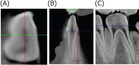
Fig 2 A , Axial view after step 2 of CBCT orientation with intersection of the coronal ( green ) and sagittal ( red ) planes; B , coronal view after step 3 of CBCT orientation with intersecting axial ( blue ) and sagittal ( red ) planes; C , sagittal view after step 4 of CBCT orientation with intersecting axial ( blue ) and coronal ( green ) planes. - 3.
By using the coronal view, the sagittal and axial planes were moved to intersect on the lingual CEJ. The coronal view was then rotated until the labial CEJ also contacted the axial plane ( Fig 2, B ).
- 4.
The sagittal plane was adjusted (in either the coronal or axial view) until the MCEJ (most coronal, mesial CEJ) was visible in the sagittal view. The axial and coronal planes were then moved to intersect at the MCEJ (axis of rotation). The DCEJ was identified in the sagittal view by using the same technique, and the view was rotated until the DCEJ also contacted the axial plane ( Fig 2, C ). The axial view was rotated slightly if MCEJ and DCEJ were not visible simultaneously in the sagittal view.
The orientation established for the first trial was saved, and 2 independent sets of measurements were made separated by 3 or 4 days. The second trial involved a new and independent orientation from the same DICOM 3 multifile, along with 2 replicate sets of measurements. The magnification used for the CBCT landmark identification was approximately 7 times.
The Dolphin 3D produced x, y, and z coordinates for each of the 4 landmarks (MCEJ, DCEJ, RA, and IE). By using the axial view, MCEJ and DCEJ were identified as the points on the sagittal plane that contacted the outer aspects of the tooth. If necessary, the points were verified in the sagittal view and adjusted. Moving the axial plane apically, in either the coronal or sagittal view, while watching the axial view, allowed the identification of RA, which was digitized on the slice just before the root disappeared while moving apically in the axial view. IE was identified in the same manner, except that the axial plane was moved coronally until the point just before tooth structure disappeared. Both RA and IE were verified in the sagittal view and adjusted if necessary. The 3D coordinates produced by these landmarks were used to calculate the 4 distances required to estimate tooth and root lengths.
Statistical analysis
Random error was assessed within trials (replicate 1 vs replicate 2) for both periapical and CBCT measurements. To assess random error between trials (between the 2 CBCT scans taken at each resolution and betweenthe 2 periapical radiographs taken at each site), the 2 replicates pertaining to each trial were averaged. Intraclass correlations and the method error statistic (ME = √[Σd2/2n]) were used to quantify reliability between replicates and between trials for both tooth-length and root-length measurements.
To assess measurement accuracy, systematic differences within and between trials were assessed. Replicates were averaged for all between-trial comparisons. Systematic differences between the actual, periapical, and CBCT measurements were also evaluated. The mean differences and standard deviations of the differences were described; differences were statistically tested with paired t tests. Statistical significance was set at P <0.05.
Results
Method error between replicates was greatest for periapical tooth (0.47 mm) and root (0.57 mm) measurements. Between-replicate method errors of the 3 CBCT voxel sizes were similar, especially for the root-length measurements ( Table I ). Between trials, the method errors were greatest for tooth-length and root-length measurements from the 0.4-mm CBCT scan (0.72 and 0.74 mm, respectively), followed closely by the periapical measurements (0.67 and 0.59 mm, respectively). The smallest method errors between trials were associated with the 0.2-mm CBCT measurements (0.17 and 0.37 mm for tooth and root lengths, respectively). Overall, the greatest method errors were associated with periapical measurements, whereas the smallest errors were associated with CBCT at 0.2 mm.
| Replicate 1 vs replicate 2 | Trial 1 vs trial 2 | |||
|---|---|---|---|---|
| ME (mm) | ICC | ME (mm) | ICC | |
| Tooth length | ||||
| PR | 0.473 | 0.999 | 0.666 | 0.997 |
| CBCT, 0.2 mm | 0.190 | 0.999 | 0.167 | 0.999 |
| CBCT, 0.3 mm | 0.315 | 0.999 | 0.266 | 0.999 |
| CBCT, 0.4 mm | 0.273 | 0.999 | 0.718 | 0.996 |
| Root length | ||||
| PR | 0.569 | 0.995 | 0.592 | 0.995 |
| CBCT, 0.2 mm | 0.357 | 0.999 | 0.371 | 0.999 |
| CBCT, 0.3 mm | 0.341 | 0.999 | 0.440 | 0.998 |
| CBCT, 0.4 mm | 0.299 | 0.999 | 0.736 | 0.995 |
Intraclass correlations for the periapical and CBCT measurements were high between replicates and trials ( Table I ). The lowest between-replicate intraclass correlation was associated with periapical root-length measurements (0.995). All other between-replicates intraclass correlations were 0.999. Between-trial intraclass correlations for tooth-length measurements were lowest for the 0.4-mm CBCT (0.996) and highest for the other 2 CBCT voxel sizes (0.999). Between-trial intraclass correlations for root-length measurements were lowest for the periapical images and 0.4-mm CBCT (0.995), and highest for 0.2-mm CBCT (0.999).
No imaging modality showed statistically significant systematic differences between replicates ( Table II ). The only statistically significant systematic difference between trials was for the 0.2-mm CBCT ( P = 0.023), but this difference was only 0.073 mm and not statistically significant after the Bonferroni adjustment for multiple comparisons. The largest mean differences were associated with periapical root-length measurements, but they were not statistically significant.
| Mean difference (mm) | SD (mm) | Significance (2-tailed) | |
|---|---|---|---|
| Tooth length | |||
| PR replicate 1 vs replicate 2 | 0.040 | 0.671 | 0.540 |
| PR trial 1 vs trial 2 | 0.073 | 0.947 | 0.582 |
| CBCT 0.2-mm replicate 1 vs replicate 2 | 0.047 | 0.265 | 0.075 |
| CBCT 0.2-mm trial 1 vs trial 2 | 0.074 | 0.227 | 0.023 * |
| CBCT 0.3-mm replicate 1 vs replicate 2 | −0.049 | 0.445 | 0.262 |
| CBCT 0.3-mm trial 1 vs trial 2 | 0.040 | 0.378 | 0.447 |
| CBCT 0.4-mm replicate 1 vs replicate 2 | −0.041 | 0.387 | 0.300 |
| CBCT 0.4-mm trial 1 vs trial 2 | 0.059 | 1.025 | 0.694 |
| Root length | |||
| PR replicate 1 vs replicate 2 | 0.100 | 0.802 | 0.206 |
| PR trial 1 vs trial 2 | 0.123 | 0.836 | 0.293 |
| CBCT 0.2-mm replicate 1 vs replicate 2 | −0.024 | 0.507 | 0.627 |
| CBCT 0.2-mm trial 1 vs trial 2 | 0.070 | 0.525 | 0.344 |
| CBCT 0.3-mm replicate 1 vs replicate 2 | −0.042 | 0.483 | 0.372 |
| CBCT 0.3-mm trial 1 vs trial 2 | −0.099 | 0.620 | 0.256 |
| CBCT 0.4-mm replicate 1 vs replicate 2 | 0.015 | 0.425 | 0.734 |
| CBCT 0.4-mm trial 1 vs trial 2 | 0.029 | 1.051 | 0.850 |
Stay updated, free dental videos. Join our Telegram channel
VIDEdental - Online dental courses


