Introduction
Miniscrews placed in bone have been used as orthodontic anchorage in extraction space closure with sliding mechanics. The movement patterns of the teeth depend on the force directions. To move the teeth in a desired pattern, the appropriate direction of force must be selected. The purpose of this article is to clarify the relationship between force directions and movement patterns.
Methods
By using the finite element method, orthodontic movements were simulated based on the remodeling law of the alveolar bone. The power arm length and the miniscrew position were varied to change the force directions.
Results
When the power arm was lengthened, rotation of the entire maxillary dentition decreased. The posterior teeth were effective for preventing rotation of the anterior teeth through an archwire. In cases of a high position of a miniscrew, bodily tooth movement was almost achieved. The vertical component of the force produced intrusion or extrusion of the entire dentition.
Conclusions
Within the limits of the method, the mechanical simulations demonstrated the effect of force direction on movement patterns.
Sliding mechanics is a typical method for extraction space closure. Friction is produced between the wire and the bracket but is not detrimental to the anchorage. The brackets slide along a stiff archwire so that bodily tooth movement can be easily achieved. This is an advantage over segmental or sectional mechanics, in which elaborate loop designs of the retraction spring are necessary.
In conventional sliding mechanics with intraoral anchorage, forces are applied to the anterior and posterior teeth. Both forces are canceled out in the whole force system consisting of the anterior and posterior teeth. Therefore, the entire dentition does not rotate in the sagittal plane. Alternatively, movement of the anchorage teeth is unavoidable.
Miniscrews placed in bone have recently been used for orthodontic anchorage in sliding mechanics. This method—miniscrew sliding mechanics—eliminates anchorage problems and easily achieves en-masse retraction of the anterior teeth. However, the orthodontic force applied from the miniscrew is an external force in the whole force system. This force can rotate the entire dentition in the sagittal plane; ie, the direction of the force has a great influence on the movement pattern of the teeth. To move the teeth in a desired pattern, the appropriate direction of the force must be selected. Therefore, the relationship between the force direction and the movement pattern should be clarified.
Schematic diagrams of movement patterns in miniscrew sliding mechanics have been presented for various force directions. These diagrams will be valid qualitatively and provide useful suggestions for treatment planning, but quantitative studies are also necessary for precise predictions of movement patterns. On the initial movements immediately after applying a force, finite element methods have been used to calculate movement patterns in miniscrew sliding mechanics. However, the initial movement is generally different from the orthodontic movement. In the case of conventional sliding mechanics, the anterior teeth tipped independently in the initial movement but moved bodily in orthodontic movement. This difference is due to a change in the force system during tooth movement. Therefore, orthodontic movement cannot be predicted from the initial movement or the initial force system.
The purpose of this article is to clarify the relationship between force direction and movement patterns in the extraction space closure with miniscrew sliding mechanics. For this purpose, orthodontic movements were simulated by using the finite element method.
Material and methods
After extraction of the maxillary first premolars, the 6 anterior teeth were retracted distally by miniscrew sliding mechanics. Assuming symmetry for both sides of the arch, a model of only the left side was fabricated. Elastic deformation of the archwire was calculated by using the finite element method. The archwire was made from a stainless steel wire (Young’s modulus, 200 GPa), 0.018×0.025 in (0.457×0.635 mm) and was divided into 3-dimensional elastic beam elements.
The mechanical response of a tooth supported with the periodontal ligament was replaced by the tooth element. It represents the 3-dimensional movement produced by elastic deformation of the periodontal ligament when forces and moments act on a tooth. The calculation method for the tooth element was explained in detail in a previous article. In this method, the tooth and the alveolar bone were assumed to be rigid bodies, whereas the periodontal ligament was a linear elastic film (Young’s modulus, 0.13 MPa; Poisson’s ratio, 0.45) with a uniform thickness of 0.2 mm. These elastic moduli were determined so that the initial tooth mobility of the maxillary first premolar calculated by the finite element method was consistent with that measured in vivo. This procedure was explained in a previous article.
To calculate the tooth elements, surface models of the tooth were made based on a dental study model (i21D-400C; Nissin Dental Products, Kyoto, Japan). This procedure consists of 3 steps. First, sectional images of the dental study model were taken by using dental cone-beam computed tomography (AZ300CT; Asahi Roentgen, Kyoto, Japan). Second, by using 3-dimensional modeling software (3D-Doctor; Able Software, Lexington, Mass), a stereolithographic model was constructed, the surface of which was patched with small triangular plates. Third, the sterolithographic model was converted to a finite element model by using meshing software (AI*Environment; ANSYS, Canonsburg, Pa).
The bracket slot was 0.018 in, which was the same size as the archwire. Brackets of the anterior teeth were ligated firmly to the archwire. On these teeth, the archwire and the brackets moved as 1 united body. Alternatively, brackets of the posterior teeth were loosely ligated to the archwire so that they would slide along the archwire, but sagittal rotation of the archwire was restricted by bracket slots of 3 mm in width.
Kinetic friction was produced in the posterior teeth when the archwire slid through the bracket slots. This friction force tended to move the posterior teeth in a distal direction. The frictional coefficient was assumed to be μ = 0.15 based on the experimental data.
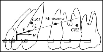
Miniscrews were placed between the second premolars and the first molars in a low position of 4 mm or in a high position of 8 mm gingivally to the archwire. Power arms were bonded to the archwire between the lateral incisors and the canines. The power arms were made from stainless steel wire (Young’s modulus, 200 GPa), 0.018×0.025 in (0.457×0.635 mm). Orthodontic forces were applied to the power arms from the miniscrews. A line joining the miniscrew with the power arm is the line of action of the force ( Fig 1 ). According to clinical cases, the magnitude of the orthodontic force was assumed to be 1.5 N (150 gf). To change the force direction, the length of the power arms was varied from 1, 4, and 8 mm.
This simulation method is closely related to that in 2 previous articles. Therefore, only the outline and the assumptions of the method are explained below.
Orthodontic movement was achieved by 3 steps. First, forces and moments acting on the teeth were calculated by using the finite element model. Second, the amount and direction of movement for each tooth were calculated based on the stresses induced in the periodontal ligament. Third, according to these amounts and directions, the teeth moved. When these 3 steps were repeated, the teeth moved step by step. The force system acting on the teeth was updated during each step. We developed a computer program for executing this procedure. A postprocessor for the finite element method (FEMAP version 6.0; Enterprise Software Products, Exton, Pa) was used for illustrating tooth movements and deformations of archwire.
Calculations of the amount and direction of orthodontic tooth movement were based on resorption and apposition of the alveolar bone (bone remodeling). The bone-remodeling rate was assumed to be in proportion to the mean stress in the periodontal ligament. Tooth movement depends on parameter CT , where coefficient C is the amount of bone remodeling (resorption and apposition) (μm) per unit of time (day) and unit of stress (kPa), and T is the elapsed time in days. Then, the unit of the CT becomes μm/kPa. Because a reasonable value of C was unknown, the progress of tooth movement was indicated by the parameter CT .
The center of resistance could not be defined for the entire dentition, since the position of the anterior teeth relative to the posterior teeth varied with space closing. Instead of that, the centers of resistance were calculated for the 6 anterior teeth and the 6 posterior teeth. These centers of resistance were defined in the same way as for 1 tooth: ie, the tooth segment could translate without rotation when applying a force to the center of resistance. The method for determining the location of the center of resistance was explained in a previous article.
Results
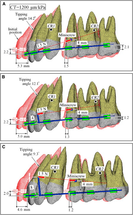
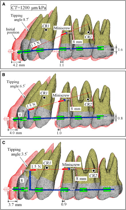
Figure 1 shows the initial locations of the centers of resistance in the anterior and posterior teeth. Figure 2 illustrates orthodontic tooth movement at CT = 1200 μm/kPa for the low-position miniscrew, when the length of the power arm is changed to 1, 4, and 8 mm. Initial tooth positions are illustrated in Figure 2 with muted red outlines . The central incisors moved distally by approximately 5 mm. The amounts of extrusion of the central incisor, distal movement of the second premolar, and intrusion of the second molar are shown in Figure 2 . Current locations of the centers of resistance for the anterior and posterior teeth are indicated with solid circles . For the high-position miniscrew, tooth movements at CT = 1200 μm/kPa are illustrated in Figure 3 . The central incisors moved distally by approximately 4 mm but did not extrude. Figure 4 illustrates tooth movement at CT = 1200 μm/kPa for the high-position miniscrew, when the power arm of the 8-mm length was shifted to the canine bracket. This movement pattern was similar to that in Figure 3 , C . The anterior teeth could move bodily irrespective of the positions of power arm.
Stay updated, free dental videos. Join our Telegram channel
VIDEdental - Online dental courses


