Fig 17.1 Seibert’s alveolar defect classification (Class I, Class II and Class III).
To augment these alveolar deficiencies, traditionally autogenous onlay bone grafts have been performed. Ridge augmentation is required not only for functional but also for aesthetic reasons in implant-supported restoration for an atrophic, narrow alveolar process. Bone grafting with autogenous bone or bone materials, guided bone regeneration (GBR), and ridge expansion techniques have been used for this purpose. However, these procedures have disadvantages, such as the need for surgical intervention and harvesting bone, unpredictable bone resorption, and difficulty in achieving soft tissue coverage.
Ilizarov established the concept of distraction osteogenesis (DO) for orthopaedic surgery in the early 1950s. Subsequently, the idea was introduced to the field of oral and maxillofacial surgery by McCarthy and associates in 1992. In 1996, DO was introduced as an effective new technique for vertical alveolar ridge augmentation, and since then the vertical alveolar DO technique is applied widely to correct alveolar ridge defects or atrophy. Unlike GBR or bone grafts, the DO technique does not need a donor site or the simultaneous lengthening of surrounding soft tissues.
Vertical alveolar distraction
In 1996, Chin et al developed a vertical alveolar distraction device, LEAD system (Stryker Leibinger, Kalamazoo, MI), consisting of a threaded rod, a threaded transport plate, and a stabilizing unthreaded base plate (< ?xml:namespace prefix = "mbp" />

In 1998, Hidding et al developed the TRACK system (Tissue Regeneration by Alveolar Callus distraction –Köln) distraction device (KLS Martin, GmbH, Tutlingen, Germany), consisting of titanium microplates welded onto the sliding mechanism of the distraction screw (
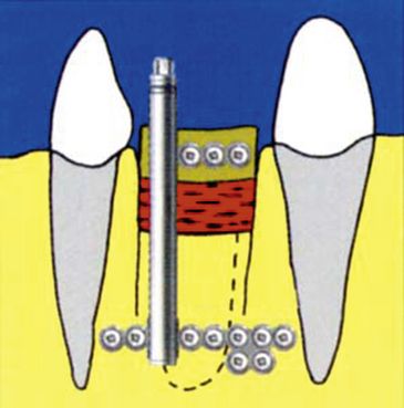
Basic concepts of vertical alveolar distraction are the same as those of Ilizarov (
Alveolar reconstruction is achieved by a bone transport technique whereby the transport segment is moved using a special distractor such as the LEAD system or the TRACK system.
Surgical technique
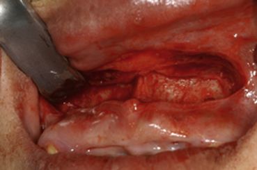
Alveolar distraction surgery is typically performed as an in-office procedure utilizing local anaesthesia and intravenous sedation. A horizontal vestibular incision is used to expose the bone at the level of the planned horizontal osteotomy. The periosteum is only minimally exposed because of its role in blood supply to the segmented bone (
The bone plates of the distraction device (Track 1.0) are contoured to the surface of the bone. The plates are also bent to give the proper distraction vector, which is chosen based on the desired direction of the distraction, the final bone segment position, and avoidance of occlusal interference (
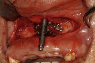
The distractor is then deactivated to its initial position, and the flap is closed in a meticulous manner (
After a 2–3 month consolidation period, the distraction device is removed, and the placement of the implants is performed (
Horizontal alveolar distraction
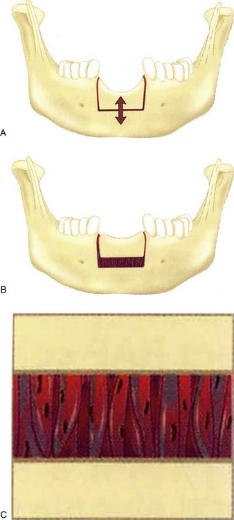
A horizontal DO for correcting a narrow alveolar ridge has also been published. Nosaka et al reported horizontal alveolar ridge distraction in a dog model and observed woven bone in the distraction gap at 12 weeks and new mature lamellar bone at 24 weeks. Funaki et al also mentioned the method of horizontal DO using a titanium mesh plate that gradually expands the buccal plate horizontally, which is very similar to ridge expansion osteotomy or the bone-splitting technique without interposition grafting. Horizontal alveolar distraction using a titanium mesh plate is an excellent augmentation technique for the placement of implants in a narrow alveolar ridge. However, previous in vivo studies were reported the transport segment underwent resorption and it requires appropriate bone volume to make a transport segment by performing an osteotomy, which placed a heavy burden on the patient. Recently the idea of osteogenesis by periosteal distraction or elevation without corticotomy for bone augmentation has been suggested. These methods indicate a new technical aspect of DO or tissue expansion, with controlled guided formation of new bone.
Devices
Horizontal alveolar distraction devices have been previously reported. ‘Calluspreader’ was developed by Gaggle et al. (
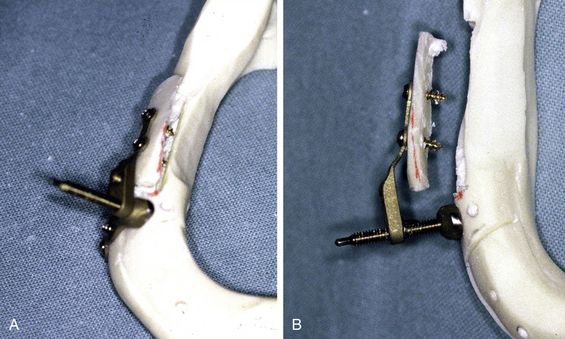
Fig 17.14 (A) Horizontal alveolar DO device ‘Calluspreader’, (B) transport segment was moved laterally followed by activation of Calluspreader.
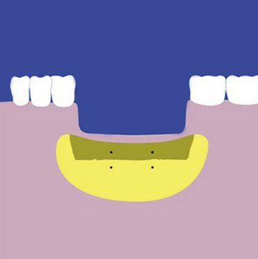
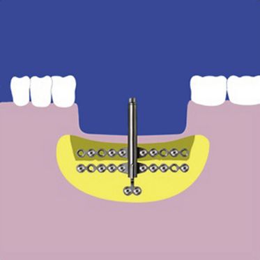
The concept of horizontal distraction is quite similar to the vertical alveolar distractor. The author and associates developed a horizontal distraction device consisting of a 0.3-mm-wide commercially pure (CP) titanium mesh plate and a pure titanium distraction screw, 2 mm in diameter and 12 mm in length (Alveo-Wider®, Okada Medical Instrument Supply Co. Ltd., Tokyo, Japan) (
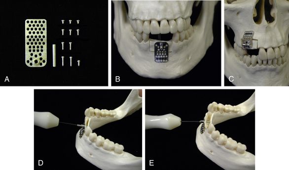
Fig 17.15 (A) Custom horizontal alveolar distraction device Alveo-Wider® of 2 mm titanium miniplate (Okada Medical Instrument Supply Co. Ltd., Tokyo, Japan). (B) Front view of Alveo-Wider® appliance for the anterior mandible. (C) Alveo-Wider® appliance for maxillary premolar region. (D) Distraction activation is done by turning distraction screw using driver. (E) Transport segment was moved laterally followed by activation.
Most of the transport segment of horizontal distraction is thin, and the segment was difficult to be fixed with a distraction device. The mesh type device used a titanium microscrew (1.2 mm in diameter) placed in the transport segment and stabilized it to the remaining mandible. The mesh structure has many holes to insert microscrews and it is an advantage to have many choices to insert the screws, especially when an inadvertent fracture occurs to the transport segment. This device is worked at a rate of 0.4 mm (0.45 mm for the prototype) from one turn, using an original driver distraction speed of 0.4–0.8 mm/day.

CASE REPORT-1
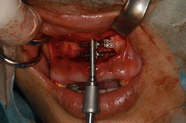
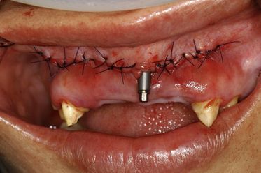
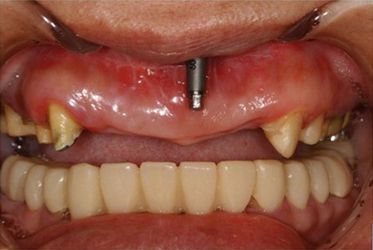
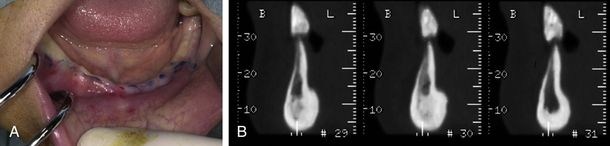
A healthy 51-year-old female presented with the chief complaint of masticatory dysfunction. She had been using removable partial dentures for the maxilla and mandible, and had been suffering from instability of the mandibular denture because of advanced periodontitis involving the abutment teeth (right mandibular lateral incisor and canine). After these teeth were extracted, she insisted on having an implant-supported prosthesis instead of a removable denture. However, her mandibular alveolar ridge showed extremely thin (
Stay updated, free dental videos. Join our Telegram channel
VIDEdental - Online dental courses


