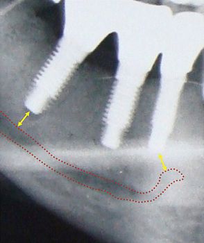
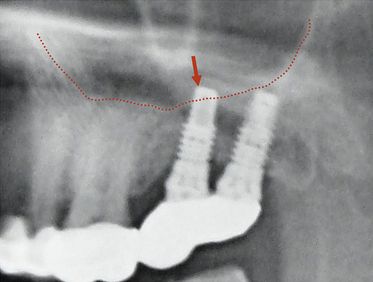
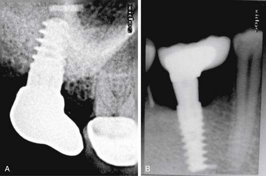
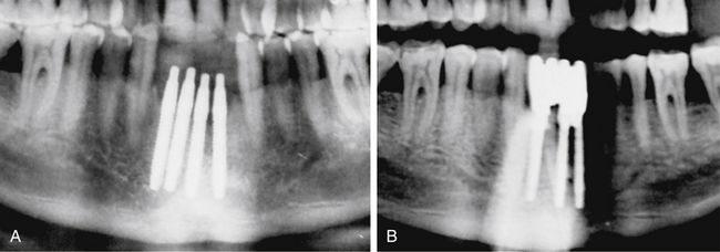
Fig 24.1 (A) Radiograph showing the pilot drill encroaching at the nerve. Further drilling reaching the same depth must be avoided and an implant with shorter length should be inserted. (B and C) If the post implantation radiograph shows that the implant has been placed through the mandibular canal, the implant should immediately be removed and another short length implant inserted or the same implant inserted with different angulation if possible, to avoid nerve injury. (D) If the patient complains of neurosensory dysfunction on the second day of surgery, the areas of anaesthesia, paraesthesia, and dysaesthesia should be marked differently on the patient’s lower jaw and photographed for future comparisons of recovery.
Prevention and management
1. Detailed radiographic and CT planning to evaluate the exact path of the mandibular canal.
2. Length of the planned implant should be 2-3 mm less than the height of the bone present above mandibular canal (3.0 mm safety distance) (< ?xml:namespace prefix = "mbp" />
3. If the case has been planned using only the panoramic radiograph, the 25% magnification of the radiograph should be reduced from the bone height measured above the canal in the radiograph. For example, if the panoramic radiograph shows 15 mm bone height above the canal, the actual bone height can be only 12 mm and after deducting another 3 mm as the safety distance, only a 9 mm long implant should be chosen for placement. However, if the dental CT scan, which shows the actual bone dimensions, shows 15 mm bone height above the mandibular canal, the surgeon can place a 12 mm long implant.
4. In the case of limited bone height above the mandibular canal, a radiograph should be taken after pilot drilling short of 3 mm from the planned implant depth, to reconfirm the canal position in respect to the implant length (
5. If the osteotomy has been prepared and the implant has been placed with its apex just touching the canal, the patient should be recalled two days after surgery and enquired if there is any altered sensation over the chin and lower lip of the same side. If the answer is “Yes”, then either the implant should be unscrewed 1.0 mm to release the pressure from the nerve or it can be removed and replaced with a shorter length implant. The patient may, however, take 2–4 months to recover from the paraesthesia.
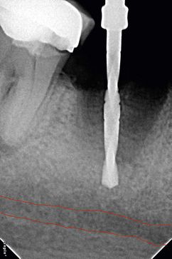
Fig 24.3 The dental radiograph with pilot drill into the osteotomy is taken to assess the distance from mandibular canal.
If the implant surgeon has severely injured or crushed the nerve, it may require microsurgical repair of the nerve, if the paraesthesia is not recovered by therapeutic measures. The nerve injury may produce short-term or even protracted paraesthesia (abnormal sensation without being unpleasant or painful) or dysaesthesia (unpleasant or painful sensation) to the patient over the lip and chin of the side.
Treatment to recover the altered nerve functions
1. Drug therapy. The following drugs should be prescribed to the patient:
2. Physical therapy. Warm compressions and massage of the paralysed area facilitate nerve restoration and relieves neural pain.
3. Microsurgical repair. If the altered nerve sensations have not even started recovering in 2–3 months, the patient should be referred to a surgeon who has expertise in performing microsurgical repair of the neural tissues. To microsurgically repair the crushed nerve, the mesial and distal ends of the nerve bundles are located, the crushed part of the nerve is resected, two to three nonresorbable sutures are placed to approximate the ends, and a collagen membrane is wrapped around the repaired nerve for predictable nerve tissue regeneration.
Dr WL Gore and Dr Flagstaff used a polytetrafluoroethylene (PTFE) tube to repair the inferior alveolar and lingual nerve. Proximal and distal ends were placed in the PTFE tube and secured using 8-0 nylon sutures. The procedure was performed in a total of seven patients and only two patients recovered from the paraesthesia.
Maxillary sinus perforation
The implant surgeon may inadvertently perforate the sinus floor during implant placement in the maxillary posterior region. If there is only a small perforation with the pilot drill, osteotomy preparation can be continued 2 mm short of the sinus floor and the implant can be placed. Small perforations spontaneously heal and do not cause any problem to implant healing. If a large perforation has been made into the sinus membrane, the surgeon can abort the implant placement and close the flap, and re-enter after it is healed in 3–4 months. Alternatively, the sinus membrane can be elevated with the lateral approach, the perforation can be repaired using resorbable collagen membrane and the implant can be placed in the same sitting. According to the traditional concept, if the implant perforates the sinus membrane and penetrates the sinus, it can be a source of periodic sinusitis. Recent studies have shown that if the implant apex has penetrated into the sinus 2 mm or less, the membrane regenerates and covers it within few weeks; and even if it has penetrated more than 2 mm, being a sterile material it does not usually cause any problem. However, further clinical trials and scientific evidence are required to prove that implant apex penetration in the sinus is safe and does not cause any long-term complication to the sinus cavity or impede implant survival (
Dehiscence/perforation through the lingual cortical plate
Perforation through the palatal cortical plate in the maxilla is very rare because of its high density and favourable topography. When the perforation occurs through the lingual cortical plate of the mandible, it is often difficult to elevate the lingual flap to such an extent as to expose the perforation (especially if it has occurred deep apically), and to graft the perforation. The appropriate way is to abort the implant placement and leave the site to heal, with or without grafting the already prepared osteotomy. Implant placement can be attempted again once the site has healed. Though very rare, a life-threatening haemorrhage may happen with the perforation of the lingual cortical plate when drilling for mandibular implants. The drill may traumatize two major arteries: (i) the lingual artery (which supplies the tongue) and its terminal branches called sublingual arteries supplying the lingual and gingival aspects of the anterior cortical plate of the mandible and (ii) the facial artery, which runs under the base of the mandible in the second molar region. Significant internal bleeding from these arteries in the floor of mouth may result in a life-threatening haemorrhage, which causes swelling of the floor of mouth and tongue, and respiratory obstruction. When such a haemorrhage is noticed, the tongue should be pulled out and pressure placed along the inner and inferior aspects of the body of the mandible. One should also compress the site with one finger intraorally over the site and another finger placed extraorally, compressing the two fingers together. A haemostatic agent should be placed into the osteotomy and the patient should immediately be transported to the hospital where a team of surgeons can ligate the injured vessels, give an endotracheal intubation, or perform an emergency tracheotomy (
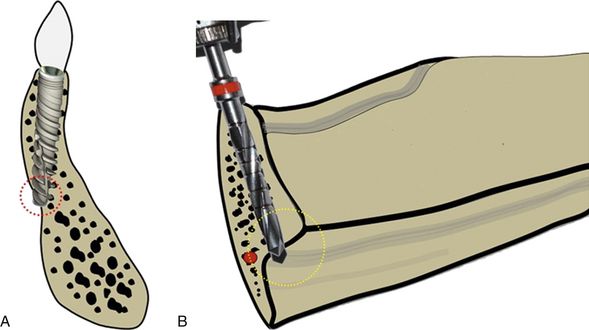
Fig 24.5 The anterior mandible is the area where the bony ridge maximally changes its axial direction through the different stages of bone resorption. (A) One should carefully evaluate the bony ridge topography to avoid any dehiscence through the lingual cortical plate during osteotomy preparation. (B) Care must also be taken to avoid the penetration through the submandibular fossa which is located below the mylohyoid line and also into the sublingual space in the anterior mandible where the sublingual artery is located. Inadvertent penetration of these lingual plates can be avoided by appropriately directing the pilot drill towards the buccal and monitoring the area with digital contact on lingual aspect while drilling.
The risk of lingual plate perforation or fenestration, due to lingual concavity, in an edentulous posterior mandible in the region of second premolar or first molar was found to be only 0.053% if a regular 3.75 mm diameter tapered implant was used. In the presence of significant lingual concavity in the posterior mandible, a smaller regular diameter implant with a stepped taper design should be considered, to avoid potential fatal damage of the vital structures.
Dehiscence/perforation through the facial cortical plate
Any dehiscence or perforation through the facial cortical plate during osteotomy preparation can be grafted using autogenous bone and/or bone substitutes, after implant placement in the same sitting (
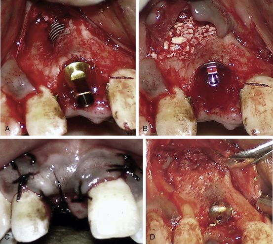
Fig 24.6 (A) A fenestration through the labial cortical plate can be seen with the implant thread exposure. (B and C) The site is grafted using Bio-Oss (xenograft) graft material and the flap is sutured back without using any barrier membrane. (D) The implant is uncovered after 4 months showing new bone formation at the grafted site.
Drilling through the root of the adjacent tooth
Drilling in the wrong direction or the presence of inclined roots of the adjacent tooth may inadvertently cause this complication (
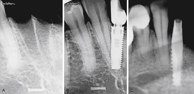
Fig 24.7 (A and B) Implant placed at the site of the madibular lateral incisor has penetrated through the canine root. (C) Implant encroaching the periodontal ligaments of the adjacent tooth.
Prevention
Meticulous treatment planning using radiographs and CT images and careful osteotomy preparation in three-dimensionally correct directions, which can be evaluated with the radiograph after the drilling to partial depth, can avoid this complication.
Management
The management of this complication depends on the severity of injury to the adjacent tooth that occurs during implant placement.
1. Encroachment only at the root apex. If the pilot drill has only encroached at the root apex, further osteotomy should be prepared in the correct direction and the implant should be placed. If the tooth becomes symptomatic, root canal therapy should be done in a follow-up visit.
If the implant has been placed encroaching the root apex, root canal therapy should be done in the same sitting using only sterile saline for root canal irrigation. The root canals should be obturated at the same sitting.
2. Perforation through the apical third. Osteotomy should be prepared in the correct direction and the implant placed. Root canal therapy with simultaneous resection of the perforated root apex should be done with the lateral approach and the area should be grafted in the same surgical sitting using any bone substitute.
3. Perforation through the middle third. The osteotomy should be prepared in the correct direction and the implant should be inserted. The tooth should be extracted and socket grafted in the same surgical sitting, using any bone substitute.
Off-axis implant placement
Off-axis implant placement not only results in a challenging situation for prosthetic rehabilitation but also causes the resorption of thin bone at the crestal region, which leads to bone defects and soft tissue recession (
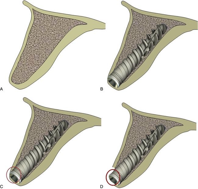
Fig 24.8 (A) The cross-section of anterior maxilla before implant insertion (B) implant placement in the incorrect direction, (C) causing thin labial cortical plate at the crestal region, (D) which fails to survive and gets resorbed.
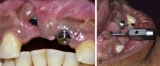
Fig 24.9 (A) The implant placed in the wrong axis resulted in loss of thin hard and soft tissue on the labial aspect if restored, (B) it will lead to a very unaesthetic prosthesis.
Management
The implant should be removed and the same or a new implant should be reinserted at the correct axis. (
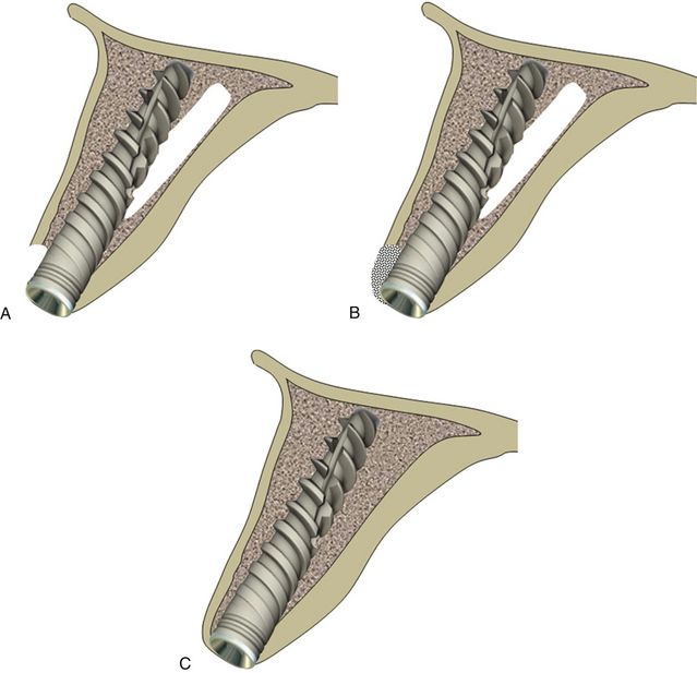
Fig 24.10 The implant can be removed and osteotomy prepared in the correct direction. (A) The same or a new implant is inserted. (B and C) The bone defect is grafted using autogenous or synthetic graft material and the flap is sutured back for submerged healing for a minimum of 4 months, which allows new bone formation at the area of the defect and implant to get osseointegrated.
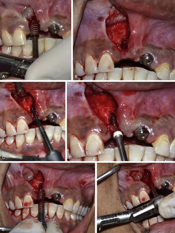
Fig 24.11 (A) The osseointegrated implant is removed using the ratchet. A papilla preservation flap is elevated to expose the implant site. (B) A bone defect is visible, which developed after the loss of thin labial cortical plate at the crestal region because of incorrect implant angulation. (C) A side-cutting Lindemann drill is used to drill the hard and thick palatal cortical plate and (D) the osteotomy is prepared in the correct direction using implant drills. (E) The same implant is reinserted with the correct angulation. (F) An adequate primary stability of the implant is achieved.
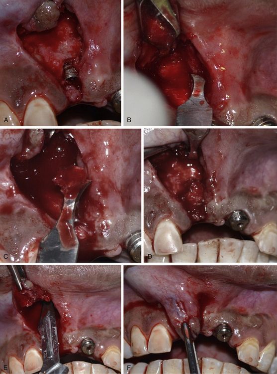
Fig 24.12 (A) The labial bone defect can be seen around the implant neck area; changing the implant direction has provided adequate room to graft the defect. (B–D) Autogenous bone is harvested from the subnasal region using a sharp chisel and used to graft the defect. (E and F) Releasing incisions are made through the periosteum of the flap to coronally advance it to achieve primary closure.
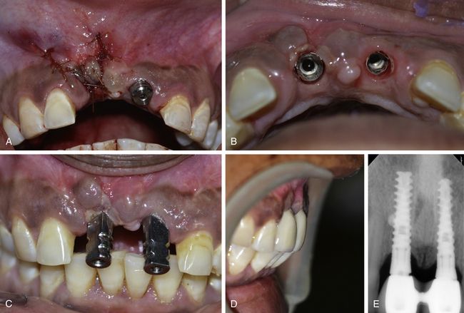
Fig 24.13 (A) The flap is sutured back with the primary closure and the site is allowed to heal for 4 months. (B and C) The implant uncovered using tissue punch shows the correct axis of the implant. (D) The implants are restored with an aesthetically acceptable prosthesis. (E) Postloading radiograph. Though, these implants are in function since 2 years with stable crestal bone level but removal and immediate reinsertion of the same implant in the same patient need further clinical trials.
Inappropriate three-dimensional implant positioning in the aesthetic region
The implant positioning should be three-dimensionally accurate in the aesthetic region to achieve optimal hard and soft tissue aesthetics. When adjacent teeth are present with the gingival collar at the correct position, the implant should be placed in such a way that its platform is finally positioned 2–3 mm apical to the imaginary line connecting the cementoenamel junction (CEJ) of two adjacent teeth, to achieve the adequate emergence profile through the soft tissue. If soft tissue recession has already occurred on the adjacent teeth, the implant platform should be positioned 2–3 mm apical to the gingival zenith. The implant platform should also be placed 1–1.5 mm palatal to the imaginary line connecting the CEJ of two adjacent teeth (
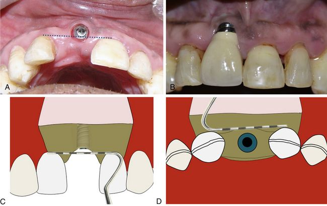
Fig 24.15 (A and B) Implant has been placed far facial and apical to the ideal position in the aesthetic region. (C) To achieve adequate aesthetic outcome, the implant should be positioned 2–3 mm apical to the imaginary line connecting the CEJ of two adjacent teeth or 2–3 mm apical to the gingival zenith. (D) The implant platform should also be placed 1–1.5 mm palatal to the imaginary line connecting the CEJ of two adjacent teeth.
Implants too close to each other
If two adjacent implants are placed very close to each other, the thin bone (less than 3 mm) present between two adjacent implants fails to survive because of lack of nutrient supply and gets resorbed (
Stay updated, free dental videos. Join our Telegram channel

VIDEdental - Online dental courses


