Correction of complex traumatic deformities remains a challenge; in the diagnostic evaluation of the deformity, in setting up the therapeutic schedule, and in the surgical correction itself. Until now, computer-assisted preoperative planning (CAPP) and computer-assisted surgery (CAS) have not been practiced as part of the surgical routine in the field of traumatic deformities. The aim of this chapter is to demonstrate the value of modern computer-assisted analysis, simulation, and especially intraoperative navigation through the use of optical navigation systems in the field of traumatic reconstructive craniomaxillofacial surgery. In our experience, the direction of development of conventional navigation systems toward a multifunctional planning-navigation-control unit sets new standards in craniofacial plastic and reconstructive surgery.
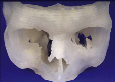
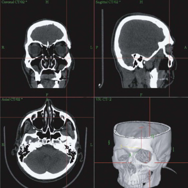
Primary diagnostics are indispensable in assessing the mostly combined bony and soft tissue deformities in major craniofacial traumatic disorders. Advances in imaging techniques such as spiral computed tomography (CT) with multiplanar reconstruction and three-dimensional (3-D) imaging and associated technologies such as stereolithographic (STL) models, have led to improved preoperative planning for the craniomaxillofacial surgeon. STL models create the 3-D situation only of hard tissue defects. They permit, to some degree, the preoperative or intraoperative manufacturing of individual implants, but they do not fulfill further requirements of reconstructive surgery. STL models, reflect just one segment within the gray scale of the acquired spiral CT dataset. Their use carries the risk of producing pseudoforamina artefacts instead of thin bony structures, which are widely present, especially in the midfacial skeleton ( Fig. 33-1 ).
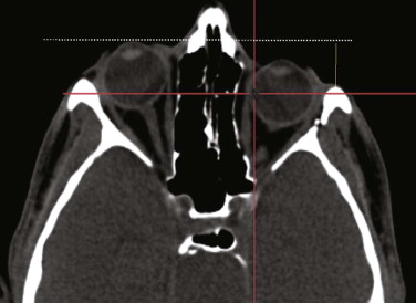
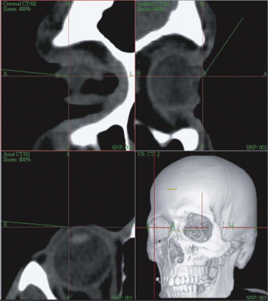
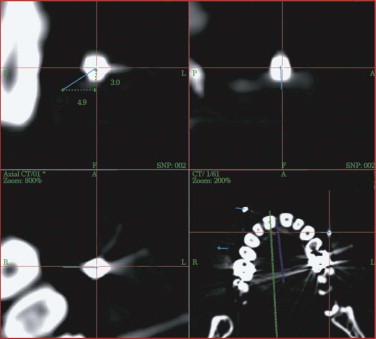
A spiral CT dataset provides information on a variety of both soft and hard tissues, limited only in the communication between radiologist and surgeon. To obtain sufficient information about the preoperative situation, surgeons must familiarize themselves with the patient’s individual anatomy. Today, modern navigation systems make it possible to increase the amount of CT/MRI information and to handle it easily. The surgeon can adjust the gray scale and reconstructions to current demands. This is particularly important in traumatic enophthalmos for precise assessment of the displacement of orbital contents before surgery ( Fig. 33-2 ). The features of CAS/CAPP are listed in Box 33-1 .
- •
Measurement of distances
- •
Volume measurements (e.g., orbital contents)
- •
Mirroring parts of the dataset to an individually created plane with virtual reconstruction of form in definable ranges
- •
Virtual insertion and positioning of autologous bone grafts, realizing preoperative simulation of augmented deficient body contours
- •
Identifying structures at risk such as the optic nerve
- •
Intraoperative navigation that allows checking of the individual anatomy online and preoperative comparison of planned contour changes
- •
Assessment of changes between the preceding measurements and the actual CT/MRI dataset when postoperative spiral CT/MRI is performed for control
CAPP, computer-assisted preoperative planning; CAS, computer-assisted surgery; CT, computed tomography; MRI, magnetic resonance imaging.
Proper assessment of asymmetry is the first and most important step before the reconstructive plan is designed. The correct measurement of distances between anatomical structures helps to determine the severity of displacement, for example, if bony prominences are displaced or deviations from the original midline or occlusal plane are concerned. Sometimes even well-established clinical measurements such as Hertel’s index are limited and must be regarded with great skepticism. They do not take into account the amount of bony dislocation at the lateral orbital rim, which is often present in severe midface fractures. In this case, objective computer-based measurement technique is advantageous: the CT-based corrected Hertel’s index (the perpendicular distance between projection of the corneal surface and the lateral orbital rim) allows for quantification of globe projection, including the additive effect of bony displacement (see Fig. 33-2 ). Further transverse, craniocaudal, and posterior-anterior measurements within the orbit suggest where the problem is situated and how much bone grafting or reconfiguration of periorbital bone is necessary. Using this planning procedure, the surgeon becomes familiar with the individual deformity in a three-dimensional manner.
Among a total of 125 patients with midface fractures and skull base deformities, severe ankyloses of the temporomandibular joint (TMJ), optic nerve decompression, complex craniosynostosis, midface skull base tumor resections, primary and secondary reconstructions and complex dental implant insertion were being treated with CAPP and CAS. Six fields of computer-based craniofacial reconstruction were evaluated.
- 1
Secondary correction of panfacial fractures
- 2
Traumatic enophthalmos with or without re-osteotomy and advancement of the malar bone
- 3
Optic nerve decompression in the treatment of traumatic optic neuropathy
- 4
Navigated endoscopic frontal sinus revision after severe skull base comminution
- 5
Combined periorbital recontouring with computer-aided design and computer-aided manufacturing (CAD/CAM) of titanium implants and autologous bone grafts
- 6
Recontouring of severe bone and soft tissue deformities by augmentation of the contours with alloplasts (e.g., calcium phosphate cement, titanium mesh)
Starting with CAPP and CAS in 1997, the protocol for CT data acquisition was to acquire spiral CT datasets (Somatom Plus 4 scanner, Siemens, Erlangen, Germany; 1-mm collimation slice thickness, 2-mm table feed, 1-mm increment) to serve for CAPP and CAS on the STN navigation system (Surgical Tool Navigator, Stryker-Leibinger, Aalen, Germany) with STP 4.0 software (Zeiss, Oberkochen, Germany). By 2010, CT data acquisition had significantly improved, and conebeam computed tomography (CBCT) was being used for planning of even more complex craniofacial deformity and navigated surgery. Modern CBCT machines such as the Zenith (Orangedental, Biberach, Germany) allows for scanning of a field of view of 24 × 19 × 19 cm. The number of patients with craniofacial deformities we have treated using CAPP and CAS exceeds 700. Planning software nowadays is independent of the navigation system itself (i-Plan 3.0, Brainlab, Feldkirchen, Germany; Voxim 6.0, IVS-Solutions, Chemnitz, Germany); it is network-based and allows for direct combination with the navigation workstations. Furthermore, STL import and export have become standard. Virtual world (.wrl) files (including color and texture of 3-D photography) can be implemented in the DICOM data format.
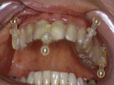
Because of the insufficient accuracy of commercially available noninvasive registration systems, the combination of CAPP with virtual correction, intraoperative navigation, and postoperative control has not yet become a routine procedure in the treatment of orbital deformities. We overcame this problem by using an individual noninvasive registration system that we developed ( Fig. 33-3 ). Thermoplastic splints are fabricated individually by a dental technician, permitting reuse in the same patient. Occlusal splints are routinely used in the upper jaw with four markers in different XYZ axes. All four markers are kept out of artifact zones such as prosthodontic restorations (see Fig. 33-3 ). The markers can be alternated according to the demands of the selected imaging modality (MRI, CT) and intraoperative use. The major advantage of this registration system is its easy reproduction, but it is limited in emergency cases in which quick assessment of a spiral CT dataset is mandatory (e.g., traumatic optic neuropathy) and in edentulous patients. In such cases, either temporary inserted bone markers or surface matching are used.
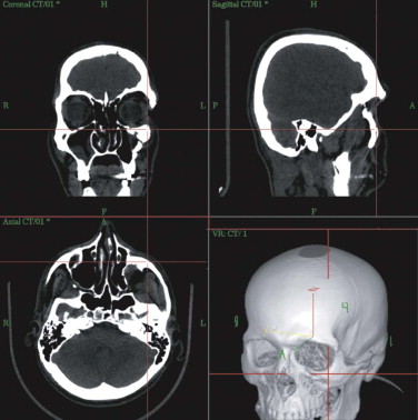
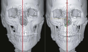
At the workstation itself, the full dataset can be adapted to the surgeon’s requirements regarding gray scale (i.e., whether hard or soft tissues are to be weighed). On the workstation, the patient’s individual anatomy is assessed in multiplanar (axial, coronal, sagittal) and 3-D views ( Fig. 33-4 ). Virtual corrections can be made by drawing new contours or by designing virtual implants at the workstation (see Fig. 33-2 ). For unilateral deformities (that do not cross the midline), the mirror tool that we developed in cooperation with the Stryker-Leibinger company in 1998, permits an ideal reconstruction by superimposing the normal side over the affected or deformed side, thereby creating a new dataset ( Fig. 33-5 ). Most traumatic and tumor-related orbital deformities are unilateral, so many cases can be approached with a side-to-side comparison. In reconstructive surgery, the surgeon must define the individual plane to which the selected range of the dataset should be mirrored from the unaffected to the deformed side. The software guides the surgeon exactly through this procedure. Intraoperatively, either the native CT dataset or the modified CT dataset can be referred to, so that navigation of the intraoperatively achieved reconstruction in comparison with the preoperative virtual correction is possible at any step of the operation. The time required for setting up and using intraoperative navigation, once mastered, is an extra 30 minutes, whereas the preoperative planning takes about 1 hour.
The limit of precision of intraoperative navigation between the virtual patient on the workstation and the actual patient on the operating table is approximately 1 mm. This can be achieved by use of the aforementioned, individually fabricated occlusal thermoplastic splints with four reference markers in different XYZ positions. Experimental and clinical evaluation of this system proved this overall accuracy of 1 mm.
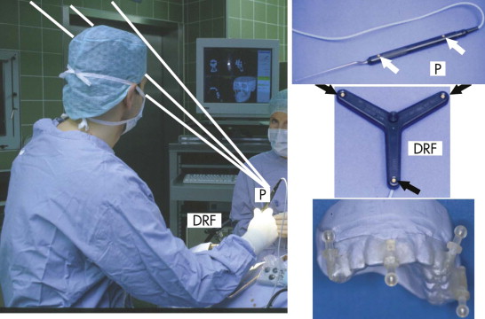
Intraoperative navigation was performed using frameless stereotaxy ( Fig. 33-6 ). Three infrared cameras controlled the pointer (P) via integrated light-emitting diodes (LEDs), and the patient’s position was controlled by a dynamic reference frame (DRF) fixed rigidly to the Mayfield clamp.
Intraoperative pointer-based navigation with the STN workstation was used not only to navigate the present bony contours but also to check on new contours, such as surfaces augmented with autologous bone grafts, bone substitutes, or advanced facial bones ( Fig. 33-7 ). The augmentation procedure was finished when the intraoperative situation matched the preoperatively planned virtual contours on the workstation.
Clinical Applications of CAPP and CAS
Correction of a Panfacial Fracture
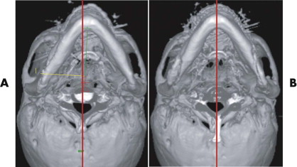
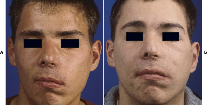
After trauma resulting in a panfacial fractures that was treated at another institution, the patient in Figure 33-8A underwent, as a first step, bilateral orbital reconstruction with autologous calvarial split-bone grafting and telecanthus correction according to the Hammer method. The second step in secondary reconstruction was to perform correction of the displaced mandibulomaxillary complex by bimaxillary re-osteotomy. CAPP was used to define the repositioning in regard to the overall asymmetry. Vectors for the ideal correction of the maxilla were defined ( Fig. 33-9 ) and were followed during later surgery with navigational control. The bony result of the bimaxillary correction is demonstrated in Figure 33-10B . Figure 33-11 demonstrates a clinical frontal view before orbital correction and after bimaxillary surgery.
traumatic Enophthalmos with and without Re-osteotomy and Advancement of the Malar Bone
Symmetry in orbital reconstruction is important for functional and esthetic reasons. Orbital asymmetry mostly results from combined soft and hard tissue deformities including the orbital contents, the bony orbit, and the periorbital soft tissues including the canthal ligaments.
Enophthalmos due to the enlargement of orbital volume is a severe complication in traumatic orbital deformities if primary reconstruction cannot be correctly achieved. Particularly in traumatic orbital deformities, measurement of sagittal globe projection can be done in the same position at the workstation as if the patient were on the operating table. The sagittal projection of the globe can be virtually marked and corrected (see Fig. 33-2 ). The globe projection changes can be measured in reference to the corneal surface and the optic canal entrance; the latter is the most reliable landmark in traumatic patients as far as quantifying sagittal changes in orbital contents is concerned ( Fig. 33-12 ). In addition to measuring functions, the software permits 3-D evaluation of orbital contents with individual figures (see Fig. 33-12 ). With this method, the orbits can be directly compared to each other and the postoperative outcome can be objectively quantified.
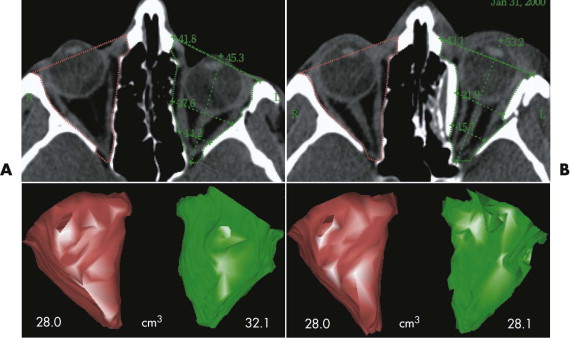
The average decrease after single orbital reconstruction in a group of 18 secondary traumatic enophthalmos corrections was 4.0 ± 1.9 cm 3 , or 65% of an average adult eye-globe volume; the average overcorrection of sagittal globe projection was 2.7 mm. However, the clinical outcome, which was achieved in all patients by only one operation, seems to justify this temporary excess in sagittal globe projection, because there is always a certain relapse in globe projection after enophthalmos correction.
Figure 33-13A shows a patient with right enophthalmos caused by midface trauma sustained 2 years earlier. The right malar bone and orbital frame were retruded. In addition, the patient showed right temporal hollowing, eyebrow displacement, telecanthus, and a displaced lateral canthal ligament. The right malar bone with the superior-lateral periorbital frame was advanced via a coronal approach. Hollowing caused by temporalis muscle atrophy was reconstructed by augmentation of the right temporal region with a calvarial split-bone graft. The orbit was recontoured using calvarial split-bone grafts. The right medial and lateral canthal ligaments were repositioned. Figure 33-13B
Stay updated, free dental videos. Join our Telegram channel
VIDEdental - Online dental courses


