Figure 1 The Hight tracer consists of (a) a mandibular plate and (b) a maxillary plate to which extension arms are attached. The mandibular extension arm has a tracing plate containing two studs over which a plexiglass plate fits. The maxillary extension arm contains a spring-loaded stylus which is encased in a threaded collar. This allows the stylus to be raised and lowered at the discretion of the dentist.
Figure 2 The mandibular portion of the device is mounted so that it is as parallel as possible to the mandibular ridge and the central bearing point is centrally located. The proper location for the central bearing point is determined by drawing a line from each canine area to the opposite second molar area. The intersection of these lines usually indicates the proper location for the central bearing point.
Figures 3 and 4 The maxillary portion of the tracer is mounted parallel to the mandibular portion. Displacing forces will be induced when the device is placed in the patient’s mouth if the two portions are not parallel.
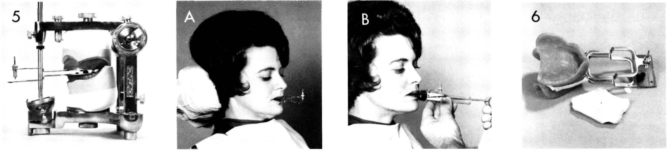
Figure 5 The central bearing point is raised until it just contacts the maxillary plate. The central bearing point should touch at the same time the incisal guide pin of the articulator touches the incisal guide table. Any variation will induce a change in the vertical dimension. The dentist may wish to raise or lower the central bearing point to alter the vertical dimension, but this will cause a change in the parallelism of the plate and should be done only with the greatest caution. This illustration shows the threaded collar in which the stylus is located on the maxillary extension arm and also shows the lock nut which maintains the collar in position. A similar lock nut is present on the inferior surface of the mandibular plate, maintaining the central bearing point at the proper height. At this stage the central bearing devices are returned to the dentist for making the maxillomandibular or jaw relation records.
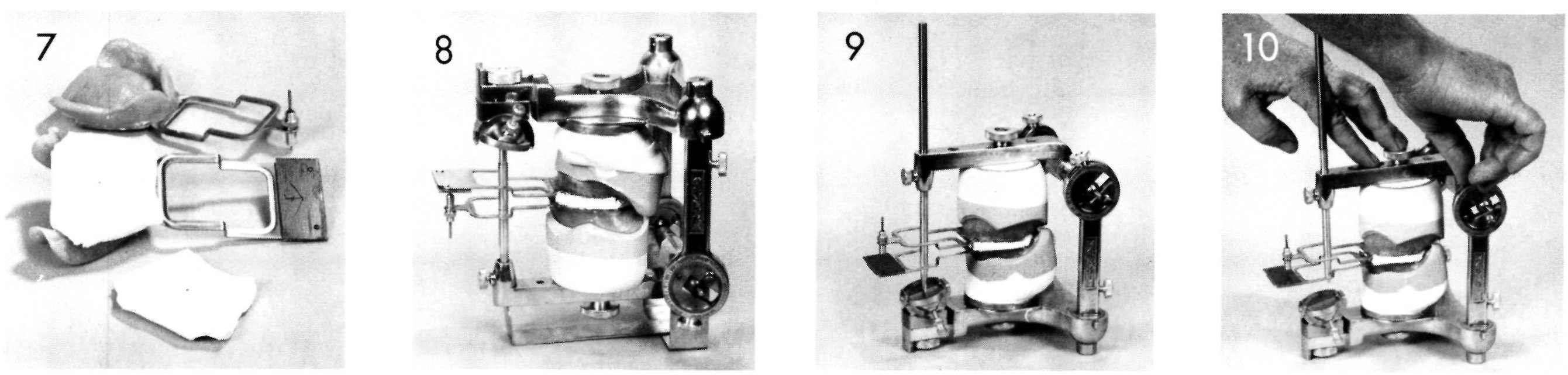
Figure A The central bearing devices are inserted and the patient is trained in their use. The arrow-point tracing is scribed by lowering the tracing stylus and instrucing the patient to make the proper jaw movements.
Figure B The dentist makes jaw relation records by injecting plaster between the plates of the tracing device. In the Hanau technique a protrusive record is usually made first and is removed from the device. Subsequently a centric relation record is made. The extra-oral device allows the dentist to verify that the patient maintains the proper position while the plaster is setting.
Figure 6 The central bearing device with the new centric relation and protrusive records is returned to the laboratory.
Figure 7 The maxillary portion of the tracing device has been removed to show the arrow-point tracing. Not all arrow-point tracings will be as symmetrical as the one illustrated. Centric relation is the point of the arrow. This illustrates that centric relation is a point and not some diffuse area.
Figure 8
Stay updated, free dental videos. Join our Telegram channel
VIDEdental - Online dental courses


