Introduction
The success rate of miniplates is superior to that of other temporary anchorage devices; nevertheless, the biomechanical behavior of miniplates during orthodontic use is not totally understood. The aim of this study was to investigate bone stress by finite element analysis when miniplates are used for orthodontic anchorage.
Methods
A 3-dimensional model consisting of a bone block integrated with a miniplate and fixation screw system was constructed to simulate various types of miniplates, screw numbers, screw lengths, cortex thicknesses, and force magnitudes and directions.
Results
The peak von Mises cortex stress values were highest with the I-type plates followed by the L-type, Y-type, and T-type plates. Bone stress decreased as the screw numbers increased but was not related to screw length. Bone stress increased as the cortex thickness decreased. Bone stress was linearly proportional to the force magnitude, and the highest values were produced when the force was in the forward direction.
Conclusions
When a T- or Y-type plate is used, or when the force direction is in the tensile mode, bone stress decreases. Bone stress also decreases as the screw numbers increase and as the cortex thickness increases. Furthermore, it decreases as the force magnitude becomes less.
Anchorage control is an important factor for the success of orthodontic treatment. Conventional anchorages might be neither sufficient nor efficient in some critical cases when there is poor patient compliance or dental conditions are poor. In 1983, the first clinical use of a screw for orthodontic anchorage was reported. After that, temporary skeletal anchorage devices were rapidly developed. There have been 3 major trends in the field of temporary skeletal anchorage devices: palatal implants, miniscrews, and miniplates. When compared with the other temporary skeletal anchorage systems, miniplates offer better stability. The average failure rates are 7.3% for miniplates, 10.5% for palatal implants, and 16.4% for miniscrews.
In the history of miniplate anchorage in orthodontics, the first use of a surgical bone plate for orthodontic anchorage was reported in 1985. Since that time, a number of miniplate systems have been specially designed as orthodontic anchors. A skeletal anchorage system, with its anchor plates and screws made of pure titanium, was developed in 1999 for use as absolute orthodontic anchorage units. The skeletal anchorage system was monocortically placed, and this allowed rigid anchorage because of the osseointegration effects on both the anchor plates and the screws. The failure rate of the skeletal anchorage system is 6%, and it shows excellent clinical performance. A zygomatic anchorage system, consisting of plates and screws, also a rigid anchorage system, was introduced in 2002. The success rate of the zygomatic anchorage system was 98.6%. In another example, a locking plate (Compact lock 2.0) has been used as posterior maxilla anchorage, and its success rate is 93.4%. Although the success rates of miniplates are superior to those of other temporary skeletal anchorage devices, the biomechanical behavior of miniplates during orthodontic use is still not totally understood. Therefore, the aim of this study was to investigate bone stress associated with various miniplate systems by using finite element analysis and taking into account the various types of plates available, the fixation screw numbers, the fixation screw lengths, the cortex thicknesses, the loading force magnitudes, and the loading force directions, with the aim of understanding the effects of these variables on orthodontic anchorage.
Material and methods
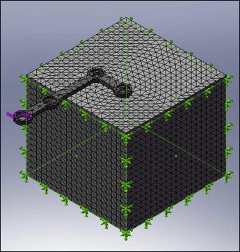
A 3-dimensional model with a bone block integrated with a miniplate was constructed by using a finite element analysis program (Dassault Systèmes; SolidWorks, Concord, Mass). This simulated a miniplate screwed into bone as an orthodontic anchorage unit. The bone block, which consisted of cortical bone and cancellous bone, was simplified to be 30 mm in length, 30 mm in width, and 25 mm in height for the evaluation. The miniplate and miniscrew geometries were based on the Mondeal System (Tuttlingen, Germany). The fixation screw had a thread profile that consisted of an isosceles triangle of 0.4 mm in height and 0.16 mm at the base, with a thread pitch of 1.0 mm. The diameter of the fixation screw was 2 mm. All materials in the model were considered homogeneous, isotropic, and linearly elastic. The fixation screw and bone plate were assumed to be pure titanium with a Young’s modulus of 110 GPa and a Poisson’s ratio of 0.35. The Young’s moduli of the cortical and cancellous bone were assumed to be 14 GPa and 1.3 GPa, respectively, and the Poisson’s ratio was 0.3 for both. The interface between the cortex and the cancellous bone was assumed to be fully bonded. Contact interface conditions were modeled between the bone structure and the plate system as well as between the plate and the fixation screws. The model was meshed with 4-node tetrahedral solid elements as shown in Figure 1 .
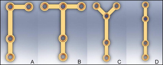
To determine the plate and fixation screw effects, 4 types of plates—L type, T type, Y type, and I type ( Fig 2 )—with 3 screw lengths (5, 7, and 9 mm)—as well as the use of either 2 or 3 screws were investigated. The screw length was measured to include the screw head, which had a height of 2 mm. To study the effect of cortex thicknesses, 3 values were simulated: 0.25, 0.5, and 1.0 mm.
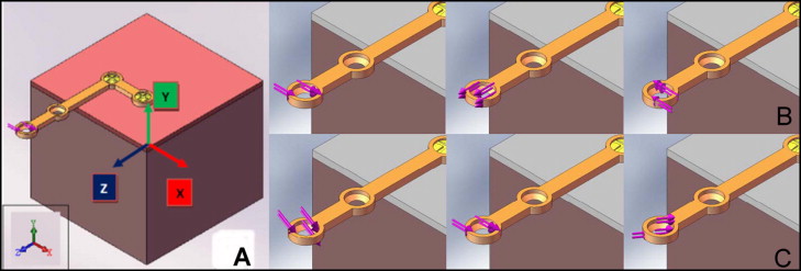
To determine the loading effect, 3 force magnitudes (2, 4, and 6 N) and 2 force directions (in-plane force and off-plane force) were investigated. The in-plane force was defined as when the loading force vector was lying on the plate plane, the x-z plane. The z-axis was determined as the axis of the plate’s long arm, whereas the x-axis was perpendicular to the z-axis, with the plate plane pointing in the direction of the short arm of the L-type plate. The y-axis was thus determined by the cross-product of the z-x axis in right coordinate system, and the y direction correspondingly was normal to the superior surface of the bone block ( Fig 3 , A ). For the first loading group (in-plane force; y = 90°) ( Fig 3 , B ), 3 loading modes were evaluated: forward bending (x = 0°), tensile force (x = 90°), and backward bending (x = 180°). For the second loading group (off-plane force) ( Fig 3 , C ), 3 loading modes were investigated involving a y force component added into the in-plane forward bending force (x = 0°). This created force directions with respect to the y-axis of 60° (downward), 90° (no downward and no upward force), and 120° (upward).
Results
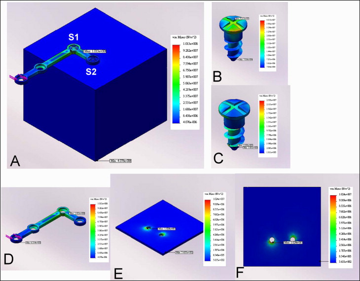
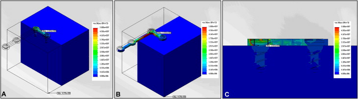
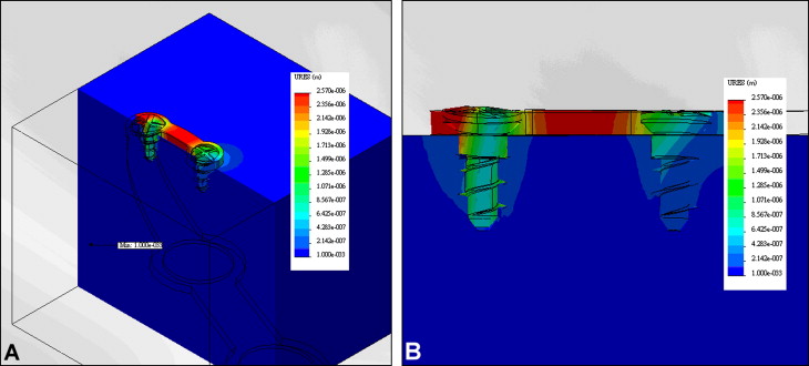
The base model was designed to have a 1-mm cortical bone thickness and to use an L-type bone plate fixed with 2 miniscrews (length, 5 mm); this was subjected to 2 N of forward bending force. Figure 4 shows the distribution of the von Mises stress values in all elements of the base model. Under the force, the long arm of the bone plate was under bending mode with the largest peak of von Mises stress occurring in the bone plate. The values of the peak von Mises stress of the plate, screw 1, screw 2, cortex, and cancellous bone were estimated as 101, 43.2, 23.1, 10.2, and 5.13 MPa, respectively. The peak stress of the bone plate was concentrated under the first miniscrew. For both screws, the peak stress occurred at the screw head. In general, the stress value of the first screw was larger than that of the second screw. In terms of cortical and cancellous bone, the peak stresses were also concentrated around the screws ( Fig 5 ). As for the displacement result, bending deformation was identified in the long arm of the plate (a gap was observed between the screw and the bone structure), and the largest displacement occurred at the loading site ( Fig 6 ).
As the bone plate type of the base model changed, there were also significant changes in the peak von Mises stress values of the bone structure. The peak values of the von Mises stress affecting the cortex were 12.42 MPa for an I-type plate, and lower values for the L-type, Y-type, and T-type plates in that sequence. With the stress of the base model set at 1, the stress ratios of the plate types are shown in Table I . As the plate changed from L type to T type and then to Y type (a symmetrical plate with short arms), the stress values in the cortex decreased by about 50% and 30%, respectively. As the plate changed from L type to I type (symmetrical plate without short arm), the stress in cortex increased by about 20%.
| L type | T type | Y type | I type | |||||
|---|---|---|---|---|---|---|---|---|
| Stress (MPa) | Ratio | Stress (MPa) | Ratio | Stress (MPa) | Ratio | Stress (MPa) | Ratio | |
| Cortex | 10.24 | 1 | 4.80 | 0.47 | 7.09 | 0.69 | 12.42 | 1.21 |
| Cancellous bone | 5.13 | 1 | 4.11 | 0.80 | 1.36 | 0.26 | 4.66 | 0.92 |
When changing the screw length of the base model, the changes in the peak von Mises stress values in the bone structure were insignificant. The smallest peak von Mises stress occurred with the 5-mm model and the base model, and these had values of 10.24 MPa in the cortex and 5.13 MPa in cancellous bone. With the stress of the base model set at 1, the stress ratios of the cortex as the screw length varied were 1.16 and 1.14 for 7-mm and 9-mm screws, respectively. Thus, as the screw size increased from 5 to 9 mm, the stress did not decrease but, rather, increased by 14%. So, the relationship between screw length and bone stress was not uniform.
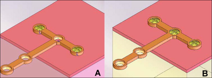
The effect of screw numbers was based on the outcomes for the T-type and Y-type plates. By using the same loading and bone structure as the base mode, both plates were secured with 2 or 3 screws. With a 2-miniscrew fixation, the screws were arranged in a symmetrical manner. Then when a third screw was added, it was always at the center ( Fig 7 ). In general, adding an extra screw at the center reduced the bone stress by 11% to 23%. With the T-type plate, when including the third screw, the peak von Mises stress values of the cortex decreased from 4.80 to 4.25 MPa. Similarly, for the Y-type plate, the stress values decreased from 7.09 to 5.49 MPa.
Stay updated, free dental videos. Join our Telegram channel
VIDEdental - Online dental courses


