Application of
Orthodontic Force
The treatment of malocclusion of teeth requires fabrication of orthodontic appliances to activate force systems. Various elements constitute an appliance. Starting with brackets, banded or bonded to the teeth, the actual forces are applied from the archwires, coil springs, and elastic modules. There are many variables involved in the structural and material properties of each component. It is important to understand these variables for construction of an efficient and tissue-friendly appliance.
The energy sources used for orthodontic tooth movement are forces originating from the elasticity of wires and elastics. A light continuous force is required for optimum orthodontic tooth movement. When the force level is maintained throughout treatment, there is a smooth progression of tooth movement resulting from direct bone resorption,1 and undesirable side effects, such as loss of anchorage or damage to the periodontal tissues, are avoided. As the tooth moves, the magnitude of force is gradually reduced owing to the structural characteristics of wires and elastics. In orthodontic practice, it is desirable to maintain a force at optimum level throughout tooth movement. To achieve this goal, the use of superelastic wires is preferred because they remain active for a long time and deliver forces at a physiologic level.
Because wires and elastics are the main sources of force application in orthodontics, it is important to know their physical properties.
Physical Properties of Materials Used in Orthodontics
Materials are composed of molecules and atoms. The distance between the grains (particles) and the connective force between them defines the hardness of the materials. When force is applied to a material, the distance between the atoms changes, depending on the nature of the force, which is called stress. The material becomes strained by the movement of the force—the stress—until it changes in size and becomes deformed.
When the stress on the material is a pulling force, the distance between the atoms increases and the material expands. This process is called tension. When the stress is a pushing force, the distance between the atoms is reduced and the size of the material decreases. This process is called compression.
When a pair of equal and opposite forces, called a couple, are applied to the material from different planes, a third kind of deformation occurs.2 This process is called shear. Tension, compression, and shear are the forms of stress that can be applied to a material (Fig 2-1).
Rubber stretches with the application of a pulling force, whereas a steel rod will not be noticeably deformed by the same amount of force. For the same amount of stress, the strain on materials varies from one to the other. Deformation of the steel rod cannot be seen with the naked eye, for instance, but there may be a change of size that can be measured microscopically.
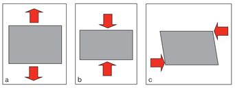
Fig 2-1 The forms of stress applied on a material: tension (a); compression (b); shear (c).
Elastic behavior of materials
A material under stress absorbs energy from the force and returns it when the stress is removed. Materials that can return the absorbed energy completely, regaining their original size when the stress is removed, are called elastic materials. Materials unable to return to their original size are called plastic materials. Coil springs are elastic, for example, whereas dead soft ligature wires are plastic. Between these extremes, viscoelastic materials can show elastic and plastic behaviors at the same time. Examples of these materials are human skin, muscles, veins, nerves, and fibers.
The concept of elasticity has a significant bearing on orthodontics because the elasticity of materials is the most important source of force used in appliance systems. An orthodontic appliance consists of active and passive units. The foremost elements that constitute the active units are sources of force such as wires, coil springs, and elastics. Activation of an orthodontic appliance or its active elements can be estimated by measuring the magnitude of the force with a dynamometer or simply by observing the deformation of the active elements. When a piece of wire is bent up to a certain point and let go, it returns to its original position. But if the force is increased excessively, and the wire is bent beyond a certain point, it cannot return to its original position. This results in plastic deformation of the wire. Figure 2-2 shows the strain of a wire onto which stress is applied. As the stress (force) is increased, the deflection of the wire increases proportionally; this constitutes the linear portion of the curve. This linear portion rises to the elastic limit of the wire, meaning that the wire will return to its original position upon removal of the stress.
The principle that applies to this section of the curve is called the Hook law, which states that “the strain is proportional to the stress applied on the material up to the elastic limit.” The slope of the linear portion of the curve, identified as the stress/strain rate, gives the modulus of elasticity, also known as the Young modulus. This value (represented by the letter E in Fig 2-2) expresses the stiffness, or load/deflection rate (springiness), of the material. Stiffness and springiness are reciprocal properties; that is, stiffness is proportional and springiness is inversely proportional to the modulus of elasticity.1–6
When the elastic limit is exceeded, the wire cannot return to its original shape upon removal of the stress because plastic deformation has occurred. When additional stress is applied, permanent deformation of the wire increases and it reaches the ultimate strength limit. Beyond this point, the molecular structure of the wire breaks down and it snaps at the failure point.
Elastic, or polymeric, materials with amorphous structure, such as rubber, show a different stress-strain curve than do metals, such as the wire in the previous example, which have crystal structure (Fig 2-3).3 When stress is first applied to an elastic, there is a linear change as there is with metal, but this linear distance is much shorter than that of metal. In elastics, the elastic limit of the material is reached sooner than in metals, so permanent deformation occurs more readily. As with metals, when the ultimate strength limit of an elastic is exceeded, the material fails.
The B slope shown in Fig 2-3 belongs to a ceramic material that does not have any elasticity, and it shows a straight line until the failure point. Materials with these properties are said to be brittle.3
In a stress-strain diagram (see Fig 2-2), the area under the slope up to the elastic limit gives the modulus of resilience of the material. Resilience is the amount of energy the material saves from mechanical work, from the passive starting point up to the elastic limit. In the same diagram, the area between points A, B, D, and C indicates the formability of the wire, and the total area under the slope from the starting point up to the failure point shows its modulus of toughness. Toughness is the total energy that can be stored from the mechanical work by the material, from the passive starting point up to the failure point.3
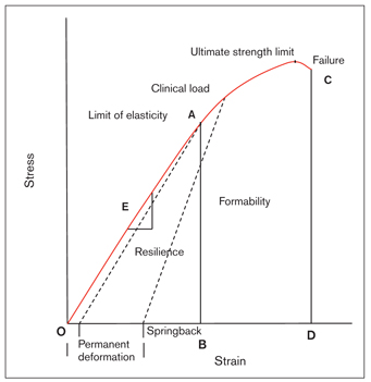
Fig 2-2 Stress-strain graph of a wire under stress. According to the Hook law, stress and strain are proportional up to the elastic limit. The limit of elasticity at point A will permit the wire to return to its original position at point O. The wire on which force is loaded up to this point and let go will return to its original position. The angle of the slope gives the modulus of elasticity (ie, the Young modulus, E) of the wire. When the elastic limit is exceeded, permanent deformation of the wire occurs. When the ultimate strength limit is reached, the molecular structure of the wire is broken down and the wire fails. The area between the points O, A, and B gives the modulus of resilience; the area between the points A, B, D, and C gives the formability; and the total area under the slope from the starting point to the failure point gives the modulus of toughness. (Redrawn from Proffit1 with permission.)
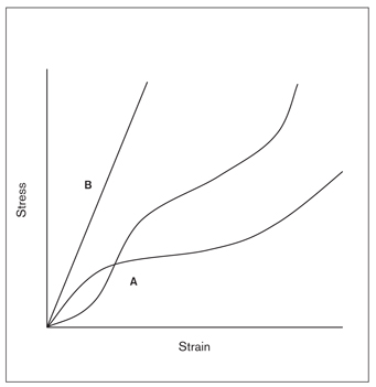
Fig 2-3 Strain-stress graph of elastic (A) and ceramic (B) materials. (Reprinted from Nikolai3 with permission.)
Wire performance
There are three properties that define the performance of a wire: stiffness, strength, and working range.
Stiffness (load/deflection rate)
Stiffness is the resistance of a wire to tension or bending. Wires with low stiffness have high elasticity, and their slope is close to horizontal. They can be bent easily, and they return to their original position when the stress is removed. Superelastic nickel titanium (NiTi) alloys are the best examples of these wires.
Wires with high stiffness show a steeper slope; high force is required to bend them. Stainless steel (SS) and heat-treated chrome-cobalt alloys such as Elgiloy (Rocky Mountain Orthodontics) are examples of stiff wires. Generally, wires of low stiffness (high elasticity) are preferred at the first stage of treatment, and wires of high stiffness (low elasticity) are used at the final stage.
Stiffness or load/deflection rates of wires are affected by three factors: size, length, and material. To change the stiffness of a wire, one, two, or all three of these factors must be addressed.
Size In round wires, the force applied by the wire is directly proportional to the fourth power of the change in wire size. For example, when the wire size is doubled, the force applied increases 16 times. If the wire size is reduced to half its original size, the force is reduced 16 times.7
If forces of the same magnitude are applied to two wires of which one is twice the size of the other, the thinner wire deflects 16 times more than the thicker one (Fig 2-4a). This illustrates the impact that size has on the stiffness of wire. In rectangular wires, however, the force applied by the wire is directly proportional to the width (ie, the “edgewise” dimension) of the wire in making first-order bends and to the cube of its thickness (ie, the vertical dimension) in making second-order bends. This means that a wire of twice the width will deliver twice the force. A wire of twice the thickness will deliver eight times the force.
Length A force applied by a wire is indirectly proportional to the cube of the wire’s length. This means that if the length of the wire is doubled, the force is reduced one-eighth; if the length of the wire is halved, the delivered force will be eight times as much. If equal forces are applied on wires of which one is twice the length of the other, the longer wire will deflect eight times that of the shorter wire (Fig 2-4b).7 The purpose of the loops is to increase the wire distance between two brackets, thus increasing the elasticity to apply long-range, physiologic forces.
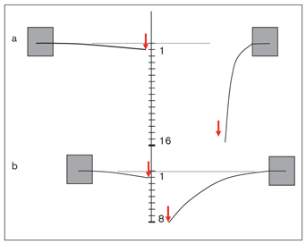
Fig 2-4 (a) The wire with half the size of the other shows 16 times more elasticity under the same force. (b) The longer wire (twice the length of the other) deflects 8 times more under the same force.
The interbracket distance is an important factor affecting the elasticity of the wire. Because the distance between narrow brackets is larger than the distance between wide brackets, the elasticity of the wire is higher where narrow brackets are used (Fig 2-5). This directly affects the amount of force delivered to the bracket by the wire. In narrow (single) brackets, the play between the bracket slot and the wire is larger than in wider (twin) brackets, and thus the force delivered by the wire is less (Fig 2-6 and Table 2-1).
This is particularly important during the initial phase of treatment, when the differences between bracket levels are considerable. At the start of the leveling phase, it is important to apply gentle forces to get cellular reaction in the periodontal tissues with tipping. Large interbracket distances and large second-order contact angles (the angles between the wire and the slot) make it possible to get faster leveling and alignment. To extrude a high canine, for example, the wire can be ligated at a single point to increase elasticity and working range and to avoid excessive moments on adjacent teeth (Fig 2-7).
Material The third factor that defines stiffness in a wire is the material from which it is made. Metal alloys have been used for several years in orthodontics. The most common wire alloys currently used are SS, cobalt-chrome-nickel (eg, Elgiloy), NiTi, and β-titanium (titanium-molybdenum alloy [TMA]). The stiffness of SS and heat-treated chrome-cobalt is very similar. The stiffness number of SS is always accepted as 1. NiTi and β-Ti wires have low stiffness compared with SS wires. Table 2-2 lists wires of different sizes and materials with equal bending stiffness.9
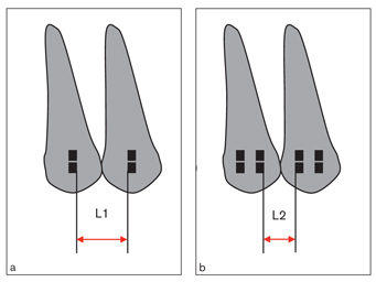
Fig 2-5 Interbracket distance is an important factor affecting the stiffness of the wire. The elasticity of the wire is higher with single brackets (a) because the distance between them is greater than the distance between the wide twin brackets (b). Therefore, the force applied to narrow brackets is less than the force applied to wide brackets.
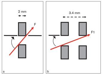
Fig 2-6 The play of the wire in a narrow single bracket slot (a) is more than that in the wide twin bracket (b). The same size of wire would deliver less force (F) to the single bracket than the twin bracket (F1).
| Table 2-1 | Second-order contact angles of different-size wires inserted into 0.018-inch and 0.022-inch brackets of three different widths*† | ||
| Wire size (Inch) | Bracket width | 0.018-inch slot (degrees) | 0.022-inch slot (degrees) |
| 0.016 | Single narrow | 1.15 | 3.43 |
| Medium twin | 0.44 | 1.32 | |
| Wide twin | 0.32 | 0.95 | |
| 0.017 | Single narrow | 0.57 | 2.86 |
| Medium twin | 0.22 | 1.10 | |
| Wide twin | 0.16 | 0.80 | |
| 0.018 | Single narrow | 0 | 2.29 |
| Medium twin | 0 | 0.88 | |
| Wide twin | 0 | 0.64 | |
| 0.019 | Single narrow | – | 1.72 |
| Medium twin | – | 0.66 | |
| Wide twin | – | 0.48 | |
| *Reprinted from Kapila et al8 with permission. †In all combinations, the contact angles of the wire with the narrow brackets are larger than those with the wide brackets. |
|||
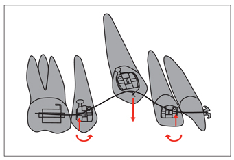
Fig 2-7 Interbracket distance has a substantial effect on wire stiffness. In leveling, if the difference between brackets is significant, the wire can be attached to the bracket at a single point to increase the length, thus increasing the elasticity and working range as well.
| Table 2-2 | NiTi, TMA, and SS wires of equal bending stiffness, according to their sizes* | ||
| Bending | |||
| NiTi | β-Ti (TMA) | SS | Relative springiness† |
| 0.016 | – | 0.0175 (3 ×.008) | 6.6 |
| 0.019 | 0.016 | 0.012 | 3.3 |
| – | 0.018 | 0.014 | 1.9 |
| 0.017 × 0.025‡ | – | 0.016† | 1.0 |
| 0.021 × 0.025 | – | 0.018 | 0.70 |
| – | 0.019 × 0.025 | – | 0.37 |
| – | – | 0.019 × 0.026 | 0.12 |
| *Reprinted from Kusy9 with permission. †Scale of relative springiness, with 0.016-inch SS and 0.017 × 0.025-inch NiTi used i lower the springiness. ‡The 0.017 × 0.025-inch (rectangular) NiTi and 0.016-inch (round) SS wires have the 0.017 × 0.025-inch NiTi can be used instead of 0.016-inch SS.1 |
|||
Strength
Strength, the second property that defines the performance of a wire, is the maximum force that the wire material can sustain. In a stress-strain diagram, the highest magnitude of force applied to the wire on the y-axis shows the strength of that wire. Strength also defines the force-storing capacity of a wire.
Working range
Working range is the maximum elasticity of a wire material before permanent deformation occurs. On the stress-strain diagram, the distance between the projection of the elastic limit and the springback point after 0.1% permanent deformation of the wire on the x-axis shows the working range of that wire. The wires with high working range are those that can work for long periods with a single activation. Superelastic NiTi and TMA wires are good examples of wires with a high working range. Stiff wires such as SS and Elgiloy, however, have a relatively low working range. Table 2-3 compares the working range, stiffness, and bending strength of 0.016-and 0.018-inch SS, TMA, and NiTi wires.1 Apart from stiffness, strength, and working range, two more properties important in orthodontic practice are springback and formability.
| Table 2-3 | Comparison of strength, stiffness, and working ranges of 0.016- and 0.018-inch SS, TMA, and NiTi wires*† | ||
| Strength | Stiffness | Range | |
| SS | 1.0 | 1.0 | 1.0 |
| TMA | 0.6 | 0.3 | 1.8 |
| NiTi | 0.6 | 0.2 | 3.9 |
| *Reprinted from Kusy9 with permission. †The stiffness of TMA is one-third that of SS, while the stiffness of NiTi is only one-fifth that of SS. On the other hand, the strength of NiTi and TMA is approximately half that of SS wires.1 |
|||
Springback
When a wire is bent and set free within its elastic deformation limits, it returns to its original point. However, if that limit is exceeded, the wire cannot return to the original point. For the same amount of activation, the possibility of permanent deformation of SS and chrome-cobalt wires is higher than that of NiTi and TMA wires.
Springback is one of the most important criteria for defining the clinical performance of wires. The force delivered by the wire to the point of deactivation is critical from a clinical point of view. Figure 2-8 compares the elasticity and springback curves of SS, Nitinol (3M Unitek), and Chinese NiTi wires. For the same amount of activation (80 degrees), SS has the lowest springback value, whereas Chinese NiTi has the highest. The characteristic that makes Chinese NiTi wire unique is that after it is activated to be engaged in the bracket, then relaxed and reactivated, it delivers nearly twice as much force as before10 (Fig 2-9).
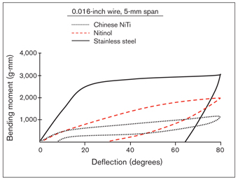
Fig 2-8 Comparison of the bending moment/elastic properties of 0.016-inch SS, austenitic Chinese NiTi, and Nitinol (martensitic NiTi) wires. Note that Chinese NiTi is twice as elastic as the Nitinol wire, and the springback property is also much higher. On the other hand, SS bent up the same amount (80 degrees) as the titanium alloy but can spring back only up to 64 degrees. (Reprinted from Burstone et al10 with permission.)
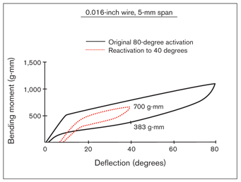
Fig 2-9 Result of activation of 0.016-inch austenitic Chinese NiTi wires, first up to 80 degrees and then to 40 degrees. The moment applied by the wire during deactivation is 383 g-mm. When the same wire is reactivated (removed from the bracket and then replaced), the force it produces at 40 degrees of activation is nearly doubled. (Reprinted from Burstone et al10 with permission.)
Formability
Formability is the area between the failure point of the wire and the permanent deformation limit on the stress-strain diagram (see Fig 2-2). This characteristic shows the amount of permanent deformation a material can sustain before it breaks.1
Testing the physical properties of materials
There are various testing methods used for determining the physical properties of wires. The simplest one is the cantilever beam test, which consists of applying force on a piece of wire of known size and length, attached firmly at one end to a block. In this test, when a force is applied to the wire from a certain point, a bending moment of F × L is generated (Fig 2-10). The wire resists bending in proportion to its stiffness, which is inversely proportional to the bending moment. This type of beam is an example of a cantilever-type, uprighting spring, but it cannot represent a multibracket system. The three-point bending test (Fig 2-11) is a better simulation of the wire-bracket relationship in a multibracket appliance.11

Fig 2-10 A cantilever beam consists of a wire of a certain length attached firmly to a block at one end. L, interbracket distance; F, force.
Fig 2-11 The three-point bending test recommended by Miura et al.11 (Reprinted from Miura et al11 with permission.)
In this test, three combinations are possible from a clinical point of view:
• The state of free movement of the wire within two brackets (Fig 2-12a)
• The state of free movement of the wire in one bracket and attachment to the other bracket (Fig 2-12b)
• The state of the wire attached to a bracket at each end (Fig 2-12c)
The formulas vary according to the type of beam, but this general formula12 is applicable to all three types:
δ = L3 × F/N × E × I
where δ is the amount of deflection, L the interbracket distance, F the force causing the beam to deflect, N the stiffness of the beam, E the modulus of elasticity of the beam material, and I the moment of inertia of the beam material.
The value of N depends on the types of supports. In beams where both ends are free, N is 48 (see Fig 2-12a). In beams having both ends attached, this value is 192 (see Fig 2-12c).
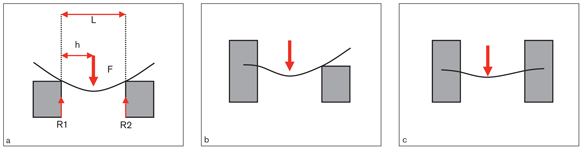
Fig 2-12 The beam type, used in the three-point bending test, wherein both ends of the wire are free (a); one end is free (b); and both ends are attached (c). Clinically, all types of beams are applicable, but the one with both ends attached seems to simulate most situations. L, interbracket distance; h, distance from the midpoint to the bracket; F, force. (Reprinted from Kusy and Greenberg13 with permission.)
The moment of inertia (I), as illustrated in Fig 2-13, is a physical parameter dependent on both the shape and size of the beam.13,14 Therefore, it is easy to determine the moment of inertia of a beam of a certain shape and size. In multistrand wires, the moment of inertia of each strand must be calculated separately.15 This is an important, variable factor when defining the elasticity of the beam. Increasing this value decreases the elasticity of the beam. In Fig 2-13, the round wire has the lowest moment of inertia, whereas the rectangular wire has the highest. Therefore, for the same beam type (the beam with both ends free, for example), the elasticity of the round wire will be higher compared with that of the rectangular wire.
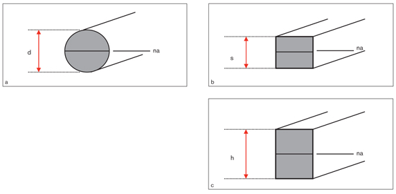
Fig 2-13 Formulas for the moments of inertia related to the cross-section of wires. (a) I = δd4/64. (b) I = s4/12. (c) I = bh3/12. (Reprinted from Kusy and Greenberg13 with permission.)
Each type of beam has different values of stiffness, strength, and working range. These properties also depend on the length of the beam; thus, the interattachment distances affect the functions of all the beam types the same way. According to the formulas previously mentioned, the elasticity of the wire between brackets is directly proportional to the cube of the length of the wire between the two attachments (see the earlier section on factors affecting the stiffness of wires). The working range of the wire is directly proportional to the square of its length but inversely proportional to its strength.
The short and long edges of a rectangular wire have different moments of inertia. The moment of inertia of the first order is higher than that of the second order (ie, the bending stiffness of the first order is higher than that of the second order). Clinically, the problems in the first order (such as rotation, crossbite, scissors bite) must be corrected with flexible round wires before rectangular wires are inserted. The transverse dimension of the dental arch can then be maintained with rectangular wire.
Fatigue
Fatigue is the weakening (reduction of elasticity) of materials under repeated stress. The weakening effect of fatigue starts where the stress is concentrated. These are the points where the size of the object shows immediate changes such as fissures, crushes, notches, cracks, and welds of two materials. The points where the wire is crushed with pliers during bending and the areas of sharp bends are the most common points where fatigue failure occurs. Clinically, failure of wires with long interbracket distances (such as 2 × 4 archwires) is a common complication. No matter what the stiffness of the wire, the reason for failure is repeated occlusal contacts or chewing cycles. Failure usually occurs at sharp bends or the points of contact between the wire and the edges of the bracket slot. The way to avoid this is to bend the wire with round-tipped pliers or heat-treat the wire to homogenize its molecular structure. Chewing forces contribute to archwire failure, even within normal in-terbracket distance. This phenomenon can be explained by the deep notches at the points where NiTi wires contact the edges of the bracket slot.
Corrosion
From the time of manufacturing, the metallic materials used in orthodontic appliances are under the influence of physical and chemical agents related to their structural properties and environmental conditions. Corrosion is the change in mechanical properties and the metal’s loss of weight under the effects of various chemical agents.
The oral environment, with its ions, carbohydrates, lipids, proteins, amino acids, and nonionic elements, is a suitable medium for the surface and deep abrasion of orthodontic attachments. Chlorine ions and the sulfuric compounds in the presence of microorganisms can corrode even SS appliances.16,17 Food and beverages are effective in shifting the salivary pH toward acid or alkaline. Long-term accumulation of food around orthodontic appliances catalyzes the corrosion. Metals (restorations, wires, bands, and brackets) and molecular solids (elastics, cement, adhesive, and acrylics) are also affected by the oral environment.3 Matasa16 and Maijer and Smith17 have studied the corrosive effects of the oral environment on orthodontic appliances. They found that these effects can manifest themselves in any of the following corrosion defects: uniform, pitting, crevicular (crevice), intergranular, microbiologic, and electrochemical.
Uniform The metal surfaces of orthodontic appliances are uniformly exposed to corrosion. The loss of weight and mechanical characteristics are in proportion to the degree of exposure. Uniform corrosion is rarely seen on orthodontic attachments themselves, as these materials do not frequently come in contact with corrosive agents.17
Pitting Pitting corrosion is the most common type seen on orthodontic attachments. The mechanical characteristics and appearance of the materials are affected more than its weight. This type of corrosion is noticed mostly on materials that have welded or soldered joints and are not well polished. Parts that are not suitably manufactured or materials containing substances that compromise their purity are more prone to becoming corroded. Matasa16 found that the chloride from salt ions is particularly responsible for this kind of corrosion.
Crevicular Crevicular corrosion is another common defect found on orthodontic attachments. It occurs especially in the presence of chlorides when the attachments are in contact with materials such as adhesives, acrylic, and elastics.16,17 SS is considered to be especially sensitive to this kind of corrosion.18
Intergranular The appearance of the metal and its weight do not change during intergranular corrosion, but there is a loss of its mechanical characteristics, and failure may even occur. This insidious attack starts from inside and can reach the grains of the metal.16 When SS is heated to a temperature of 400ºC, there will be a loss of chromium carbide at the granular borders, which renders the metal sensitive to this type of corrosion.18
Microbiologic The surfaces not in contact with air, such as the bracket base, may be affected by microbiologic corrosion.19 Various microorganisms such as Desulfovibrio desulfuricans and Desulfotomaculum; oxidants such as Thiobacillus ferroxidans and Beggiatoa; and Thiothrix, Aer-obacter, and Flavobacterium; produce sticky and humid matter, which affects the iron in SS. There are also iron-consuming microorganisms such as Sphaerotilus, Hypho-microbium, and Gallionella.16
Electrochemical Saliva serves as a good medium for electrolytic reaction between metals. There is constant friction between the wire and the bracket slot, and this causes fretting corrosion on the metal surfaces in contact and possible appliance breakage. As a result of corrosion, heavy metals such as nickel, cobalt, and chromium deteriorate in the oral environment. This is particularly important for patients with sensitivity to nickel. To overcome the predisposition of metal alloys to corrode, titanium brackets and wires have been introduced.16
Force Elements Used in Orthodontic Appliances
To obtain quick and optimal tissue reaction, ideal force application is essential. For example, the force advised for successful canine distalization in sliding mechanics is approximately 150 to 200 g.20,21 For this purpose, a variety of active elements such as coil springs, elastics, and loops can be used. An ideal force element in an orthodontic appliance should possess the following characteristics:
• Be able to deliver a constant and continuous force at optimum level
• Be hygienic and comfortable for the patient
• Be applied easily with minimum chair time
• Not be dependent on patient cooperation
• Be cost effective21
Wires
Stainless steel wires
SS wires are materials with high strength, high stiffness, low working range, and low springback properties.1,13,22–24 High formability and low manufacturing costs have made them the most commonly used alloy for years. Because of their high stiffness, they are not suitable for the leveling stage. Their load/deflection rates must be reduced for them to be used in this period of treatment. To achieve this, either the length of the wire must be increased or its diameter reduced. However, reducing the load/deflection rate makes control of tooth movement more difficult.
The classic method of increasing wire length is to add loops. Because the force applied by the wire is inversely proportional to the cube of its length, the amount of force in looped wires decreases considerably. On the other hand, as their working range increases, the wires stay active for a long time.
Reducing the size of the wire is another method of decreasing the load/deflection rate, but this is limited to the sizes of wires on the market. Although reducing the size may increase the elasticity of the wire, it also increases the play between the bracket slot and the wire, which, in turn, results in loss of control over the tooth. For optimum force and movement control, the difference between the wire and the bracket slot size must be at least 0.002 inches.1
Multistrand wires Multistrand wires are manufactured by winding several thin SS wires onto one another. Their elasticity is relatively high, as their length increases with winding. The three-or five-strand round and eight- or nine-strand rectangular wires have been commonly used in clinical practice (Fig 2-14).
Loops
Loops have been used in fixed orthodontic treatment for many years. SS and chrome-cobalt are commonly used materials because they have a high range of bending stiffness. The main purpose of adding loops is to increase the elasticity of the wire by increasing its length. With the introduction of recently developed wires having high elasticity, strength, and wide working-range properties (eg, NiTi and TMA), loops are no longer used as much.
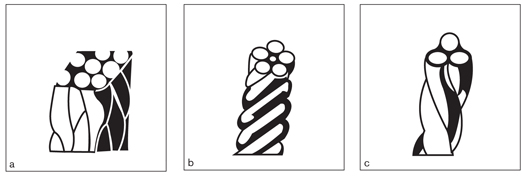
Fig 2-14 Types of multistrand wires.
Loops can have various shapes according to their purpose. They can be categorized as vertical, horizontal, combined, and special-shaped loops. It has been shown that the moment-to-force (M/F) ratio of a loop increases when more wire is added gingivally.25,26 Loops are effective auxiliaries to open and close spaces and to correct inclinations and rotations if they are bent correctly and used properly. However, they can have certain disadvantages, too. First, because of increased elasticity, movement control might be more difficult. As soon as their “mission” is accomplished, they should be replaced with straight wire. Second, loop arches may cause hygiene problems and soft tissue irritation. Round wires should be especially avoided because they can easily roll within the bracket slot and irritate the gingiva. Irritation seldom occurs with rectangular wires. Even if it does happen, the wire can be bent outward with a finger while holding both sides of the loop with torque pliers to prevent bracket debonding.
Chrome-cobalt alloy wires
The physical characteristics of chrome-cobalt wires are very similar to those of SS.13 Known on the market as Elgiloy, these wires consist of 40% cobalt, 20% chromium, 15% nickel, 7% molybdenum, and 15% to 20% iron. Elgiloy has different stiffness categories defined by four colors (ranked from the softest to the hardest): blue, yellow, green, and red. Soft (1.19) Elgiloy wire can be increased up to 1.22 with heat treatment.24 Elgiloy wire is usually used in the Ricketts bioprogressive technique.
Nickel titanium wires
The properties of NiTi wires were discovered by Buehler in 1968, but their introduction to orthodontics and their development were realized later by Andreasen and Morrow.23 The name of the first commercially available product, Nitinol, is derived from nickel titanium and Naval Ordnance Laboratory, where it was discovered during US space research.
Titanium alloy wires are marketed under the names smart wires, shape memory wires, superelastic wires, and others, but while some of them have these properties, most of them do not. It is necessary to understand the properties of these wires to make a proper selection and use them correctly.
Metallurgic properties NiTi wires are employed in either of two different crystal structures known as marten-site and austenite,27 depending on the temperature conditions in which they are used and the mechanical stresses acting on them. Austenite is seen in the higher temperatures and martensite in lower temperatures.1,27 Austenite is a highly resistant, cagelike structure; marten-site is actually a type of austenite that shows elastic shaping under heat and mechanical stress. The temperature at which austenite changes to martensite is called the transition temperature, and it is related mainly to the composition of the alloy. This process of conversion is called martensitic transformation, and it is reversible and can be repeated as much as needed.
Three main characteristics of NiTi wires make them different from SS and chrome-cobalt:
• High elasticity
• Shape memory
• Resistance to permanent deformation28
NiTi wires are twice as elastic as SS wires, and their modulus of elasticity is 26% that of SS.4 With these properties, NiTi alloys are ideal for leveling. However, as permanent deformation is directly related to time, some deformation can be expected while they are in the mouth.4,10 Even though Nitinol has an extremely high springback property, because it is produced by a cool-hardening process, it does not have the superelasticity and shape memory of some of the other NiTi wires.11 Shape memory is the shape-remembering process that allows the alloy to easily return to its original shape after being heated above a certain transition temperature.29
Superelasticity The term superelasticity, used for some NiTi wires, means that a wire can maintain a certain level of stress until a specific deformation point is reached and can keep that constancy on deactivation.29 In other words, superelasticity is the force constancy that a wire can deliver, independent of the level of activation.11,27 Miura et al11 have shown that superelastic Japanese NiTi wire, marketed as Sentalloy (GAC), applies a fairly stable force (Fig 2-15). This force application has the desired physiologic properties for tooth movement and patient comfort.29 Another superelastic wire, Chinese NiTi, shows 1.6 times more elasticity than Nitinol (see Fig 2-8).10 During activation of a superelastic wire, when the stress reaches a certain level without a change of temperature, the wire converts from austenite to a martensitic structure and returns to austenite when the stress decreases to a certain level during deactivation.
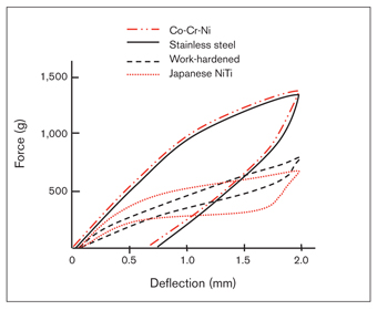
Fig 2-15 Comparison of superelastic Japanese NiTi (Sentalloy) wires with other wire alloys. Note that this wire applies more stable force compared with other wires. This is clinically important because constant and continuous force is desired to obtain optimal tooth movement. Co-Cr-Ni, cobalt-chrome-nickel. (Reprinted from Miura et al11 with permission.)
A typical stress-strain diagram of superelastic wires is shown in Fig 2-16. When the wire is activated and the amount of force increases, the alloy transforms from the austenitic to the martensitic phase. When the force is removed, the wire follows a different path below that of activation, and returns to the austenitic structure. The difference between these curves is called hysteresis. This defines the difference between the force given for activation and the force applied by the wire during deactivation. This also shows the level of force a wire delivers to the tooth. Clinically, low hysteresis is desired. Light forces should be used, especially on incisors and premolars.1,30,31 However, Segner and Ibe32 showed experimentally that very few of the archwires tested deliver a clinically desired force level. Therefore, at the beginning of treatment, NiTi wires should be tied loosely to the brackets to avoid excessive force. This is important especially on the mandibular incisors with thin roots, where the interbracket distance is short.32
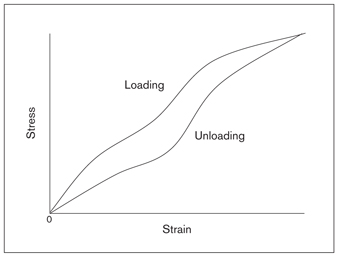
Fig 2-16 When a superelastic wire is activated, the material is transformed from the austenitic phase to the martensitic phase, and it follows a different path during deactivation. The difference between these two curves, called hysteresis, shows the clinical effectiveness of that wire.
Superelastic wires remain in the austenitic structure at body temperature, changing to the martensitic phase when a mechanical stress is applied.1,27 Copper Ni-Ti (Ormco) wires that become active at mouth temperature are also superelastic with shape memory. They are manufactured according to four transition oral temperatures (ie, 15ºC). The difference between mouth temperature and the transition temperature determines the amount of force the wire will deliver. As this difference increases, the force delivered by the wire also increases. For example, in an oral environment of 36ºC wire will be much higher than that of a wire of 40ºC. These forces, that is, the transition temperature to be selected, will be determined according to the pain threshold of the patient and the desired duration of force (ie, continuous versus interrupted). For instance, the manufacturer recommends using 40ºC wire for leveling an impacted canine. These wires, because of their high springback properties and low hysteresis, deliver very light forces, thus producing continuous tooth movement33 (Fig 2-17).
Another characteristic making NiTi wires different is that they are not bendable, solderable, or weldable, like
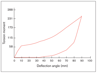
Fig 2-17 Hysteresis of thermally activated wires (Copper Ni-Ti) is low, and their springback is high. (Reprinted from Sachdeva33 with permission.)
SS. Because of their high elasticity, loops are not practical on these wires. In daily practice, however, some small bends such as step-up, step-down, and stop bends can be made when necessary. Sharp or repetitive bends should be avoided to prevent breakage. Currently, some companies put midline stops on NiTi wires to prevent them from sliding through the slots and poking the cheek. If a cinchback is needed, it can be done by annealing the end of the wire with a clinical torch before placing it in the brackets.
Clinical performance From a clinical perspective, the effectiveness of superelastic wires can be a controversial topic. In a comparative study of patient discomfort over a 2-week period, no statistically significant difference was found between 0.014-inch superelastic Japanese NiTi wires and 0.0155-inch multistrand SS wires.34 Jones et al35 measured the velocity of crowding correction with a reflex metrograph between 0.014-inch Sentalloy and 0.0155-inch multistrand wires and found no statistically significant differences between the two materials. Similarly, in a comparative study between 0.016-inch superelastic Titanol (Forestadent) and conventional Nitinol, no significant difference in the velocity of tooth movement was found at the end of a 35-day period.36
β-Titanium molybdenum alloy wire
β-Ti (TMA) wires were introduced into the world of orthodontics in 1979 by Burstone and Goldberg.37 Their elastic properties are between those of SS and NiTi. Despite their high elasticity, TMA wires are formable, solderable, and weldable—unlike NiTi alloys. Their modulus of elasticity is nearly twice that of Nitinol and one-third that of SS.1,14,37 They have a broad working range as well as high biocompatibility.38
TMA wires have higher frictional values and surface roughness than SS and NiTi alloys. That is why they are commonly used in segmented arch mechanics rather than sliding mechanics. However, studies have shown that with ion implantation, the surface hardness of the material can be increased and surface roughness reduced to reach a frictional value comparable with SS wires. Because TMA wires with processed surfaces have twice the springback of SS, they can be used as straight leveling or finishing archwires.39
Wire selection in the clinic
In clinical orthodontics, selection of an archwire requires consideration of not only its physical properties but also factors such as the severity of malocclusion, desired type of tooth movement, and treatment methods. Some of the properties expected from various wires used in orthodontic appliances are as follows:
• Must be sufficiently elastic; should not deform easily
• Must be formable and strong
• Should not be affected by oral fluids, acids, and other chemicals
• Should not corrode, rust, discolor, or oxidize
• Must be esthetic
• Should not be affected by heat or cold
• Must be inexpensive
Comparison of wire alloys
Kusy40 and Kusy and Dilley41 have studied the bending and torsional properties of SS, NiTi, β-Ti, and multistrand wires, with interesting results (Tables 2-4 to 2-6). Some of the results of these studies are as follows:
• The stiffness ratios of 0.012-inch SS to 0.018-inch NiTi and those of 0.014-inch SS to 0.018 × 0.018–inch NiTi are the same (0.8) (see Table 2-4
Stay updated, free dental videos. Join our Telegram channel
VIDEdental - Online dental courses


