Analysis of Two-Tooth
Mechanics
This chapter details the force systems created by straight and bent wires placed in the brackets of two-tooth segments. In a crowding case, to align teeth positioned at different angles and levels, an elastic, straight archwire in the brackets is engaged. The teeth move in response to the wire’s elasticity. This creates a force system formed by one wire and multiple brackets. Over time, this force system will reach static equilibrium. The first condition needed for this to occur is for the sum of the vectors of all the forces and moments on the system to be zero. However, to decipher all the forces and moments in a complete dental arch is extremely complex because of the differing anchorage values of multiple teeth, each having brackets and tubes of different widths and being located at various angulations and levels to each other. Therefore, for simplicity, this chapter considers two-tooth mechanics, as suggested by Burstone and Koenig.1
Statically Determinate Force Systems
If the distance between two attachments is known and if the force applied by the wire on the bracket can be measured with a dynamometer, the final positions of the teeth can be predetermined. In other words, the moment-and-force system can be controlled in order to guide the tooth movement. This is called a statically determinate force system.
For example, Fig 3-1a shows a canine and a premolar with equal anchorage values. A round, flexible straight wire is placed in the premolar bracket and attached to the canine bracket. If the interbracket distance is 7 mm, and the force needed to activate the wire up to the canine level is 100 g, a counterclockwise moment of 700 g-mm should be applied to the premolar bracket. Because the anchorages are equal, the center of resistance of this force system is at the halfway point. For the system to reach static balance, the algebraic sum of all the moments and forces acting on the system must equal zero. The counterclockwise moment on the premolar must be balanced by the clockwise moment created by the equal and opposite vertical forces acting on both teeth. Therefore, when the wire is engaged in the canine bracket, a counterclockwise moment of 700 g-mm on the premolar and balancing vertical forces of 100 g on both sides occur. When the wire is totally deactivated and the teeth reach a statically balanced position, the premolar tips mesially and intrudes while the canine extrudes. However, the canine cannot reach the occlusal plane (Fig 3-1b).
If the premolar in the previous example is replaced with a molar having a higher anchorage value than the canine (Fig 3-2a), then the force system will be different. In this case, a 700 g-mm counterclockwise moment occurs on the molar. This moment is balanced by a 125-g upward force on the molar and a 75-g downward force on the canine. This changes the force system in two ways. First, according to lever principles, as the center of resistance of the system is closer to the molar, the magnitude of the balancing force on the molar is higher than that of the canine. Second, from a clinical point of view, because the molar’s anchorage is much higher than the canine’s, it does not move. On the other hand, although the magnitude of force is low, extrusion of the canine to the occlusal plane occurs easily (Fig 3-2b).
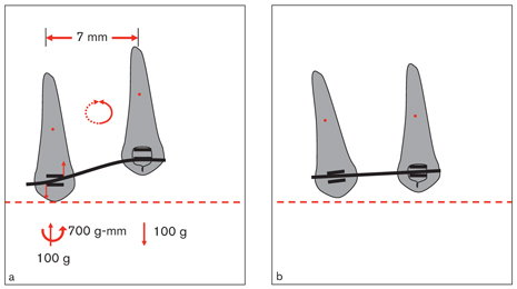
Fig 3-1 Two teeth, a premolar and a high canine with equal anchorage values. (a) When a section of wire is placed in the premolar bracket slot and is activated by ligating to the canine, a force system consisting of two teeth and a wire is created. This force system reaches static equilibrium by intrusion (ie, an upward balancing force) and a slight counterclockwise tipping of the premolar as well as extrusion (ie, downward balancing force) of the canine. (b) Note that the canine cannot reach the occlusal plane because there is some intrusion of the premolar and the anchorage values are the same for both teeth.
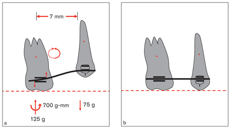
Fig 3-2 Two teeth with different anchorage values. (a) If a segmented wire is placed in the molar tube first, then deflected up to the canine and tied at a single point as shown in Fig 3-1, then a counterclockwise moment occurs on the molar. This moment reaches static equilibrium by the vertical balancing forces tending to rotate the system clockwise. These balancing forces are intrusive on the molar and extrusive on the canine. (b) Note that the canine reaches the occlusal plane because of the heavier molar anchorage. The molar resists tipping because the anchorage is large enough to resist any movement.
The relationship between crowded teeth is often complex, which makes it difficult to predetermine tooth movement. Axial inclinations and bracket positions of crowded teeth vary greatly. The previous examples were concerned only with the anteroposterior relationships of two teeth on the same plane, and they did not involve the rotations or angulations of related brackets. When a wire is engaged in two brackets, it affects the teeth in three planes of space (ie, sagittal, transverse, and vertical).
Burstone geometry classes
As the following examples illustrate, different ratios between bracket angulations affect tooth movements. Burstone and Koenig1 named six geometry classes that can occur between two teeth (for simplification, only the deactivation force systems are shown here). As a starting point, Fig 3-3 shows a 0.016-inch straight wire in two brackets of the same width on the same plane with an interbracket distance of 7 mm. Assuming that the anchorages of the teeth are equal and the wire is not active, no movement occurs. In Fig 3-4, each of the six geometry classes proposed by Burstone and Koenig1 is illustrated as the angulation of the left bracket is changed while the right one is kept stationary. Figure 3-5 shows the shape a straight wire takes when it is placed in the bracket slots for each of the geometry classes.
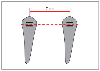
Fig 3-3 When a wire is placed in the brackets of two teeth that have the same anchorage values and are on the same plane, these teeth will not move because the wire does not apply any force on the teeth.

Fig 3-4 Geometry classes according to Burstone and Koenig.1 The proportional relationships between the positions of the left (A) and right (B) brackets are shown in the top rows, the ratios between left and right moments are shown in the center rows, and the direction and magnitude of the moments and forces (deactivation) that occur on the left and right brackets are shown in the bottom rows. Note that in Class IV geometry, the wire creates a moment of 1,860 g-mm as it enters the right bracket at an angle, whereas it enters the left bracket passively at no angle. (Reprinted from Burstone and Koenig1 with permission.)
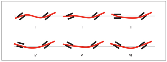
Fig 3-5 The shape of the wire after being placed in the brackets in the six classes of bracket angulation as explained in Fig 3-4. Note that in Class I and Class II geometry, the wire passes over the interbracket plane, while in the other relationships, it remains below this plane. In Class VI geometry, the proportional relationship between the brackets is -1.0. As the brackets are placed at equal and opposite angles, the shape of the wire becomes symmetric; therefore, the moments on both sides are equal and opposite.
Class I geometry
In Class I geometry, the ratio between bracket angulations is θA/θB = 1. Therefore, the angulations of the brackets are equal and their direction is the same. Since the wire-bracket angulations are equal, clockwise moments of 1,860 g-mm occur on each bracket. Because the moments are equal, the ratio between the moments is MA/MB = 1. To reach a statically balanced position, the sum of all the moments and forces acting on the system must be zero. In this system, clockwise moments (1,860 g-mm) are acting on both brackets; thus, the sum of the clockwise moments is 3,720 g-mm. For the system to be statically balanced, net forces of 531.4 g occur in an upward direction on the right and in a downward direction on the left. According to the L × F formula, the system becomes balanced with a counterclockwise moment of 7 × 531.4 = 3,719.8 g-mm. From the clinical point of view, when such a force system reaches a statically balanced position, both teeth make clockwise rotations, the right one extruding and the left one intruding.
Class II geometry
In Class II geometry, the ratio between bracket angulations is θA/ θB = 0.5, and the ratio between moments is MA/MB = 0.8. Since the angulation of the bracket on the right does not change, the amount and direction of the moment acting on this bracket remain the same (ie, 1,860 g-mm in the clockwise direction). Because the wire-bracket angulation on the left bracket is lower than the other, the direction of the moment remains the same, but its magnitude is reduced to 1,488 g-mm. The sum of the moments in the clockwise direction affecting the system is 3,348 g-mm. To balance this, the amount of balancing force for each bracket must be F = 3,348/7 = 478.2 (although researchers1 found a force of 477.4 g to be effective). Because the anchorage values of the teeth are assumed to be equal, the magnitude of the balancing forces on both sides is also equal. This system is balanced with clockwise rotations on both sides; the right tooth extrudes and the left one intrudes.
Class III geometry
In Class III geometry, the ratio between bracket angulations is θA/ θB = 0, and the ratio between moments is MA/MB = 0.5. The same results as the previous examples will be achieved because the moment on the right bracket is in a clockwise direction with a magnitude of 1,860 g-mm; the moment on the left bracket is in the same direction, but the wire-bracket angulation is less (930 g-mm). The total clockwise moment in the system (2,790 g-mm) is balanced with a net force of 398 g that rotates the system counterclockwise. When the system reaches a statically balanced position, both teeth rotate in the clockwise direction and the right tooth extrudes while the left one intrudes.
Class IV geometry
In Class IV geometry, the ratio between bracket angulations is θA/ θB = -0.5, and the ratio between moments is MA/MB = 0. Note that there is no moment acting on the left bracket. This means that the wire enters the left bracket slot without any angulation. In this case, there is only a clockwise moment of 1,860 g-mm in the system. When the system reaches a statically balanced position, the right tooth rotates in the clockwise direction and extrudes with 265.7 g, while the left tooth remains straight and intrudes with the same amount of force.
Class V geometry
In Class V geometry, the ratio between bracket angulations is θA/ θB = -0.75, and the ratio between moments is MA/MB = -0.4. In this relationship, there is a clockwise moment of 1,860 g-mm on the right and a counterclockwise moment of 740 g-mm on the left. For the system to be statically balanced, a counterclockwise moment of 1,860 – 740 = 1,120 g-mm is needed. Therefore, an upward force of 1,120/7 = 160 g on the right and a downward force of the same magnitude on the left occurs. As the system becomes balanced, the tooth on the right rotates clockwise and extrudes while the one on the left rotates counterclockwise and intrudes.
Class VI geometry
In Class VI geometry, the ratio between bracket angulations is θA/ θB = -1, and the ratio between moments is MA/MB = -1. Note that the angulations of both brackets are equal, but their directions are opposite. Because the bracket angulations are equal, the entrance angulations of the wire in the brackets are also equal. In this case, equal and opposite moments occur on both sides, and the system is statically balanced. Therefore, there are no balancing forces in this system.
Summary
Teeth can be classified as independent units, each with its own center of resistance. When a tooth moves, the other teeth will also move to some extent. All the teeth in a dental arch ligated to an archwire move with the elasticity of the wire by taking support from each other (called reciprocal anchorage). When the archwire reaches a statically balanced position, the occlusal plane will have a certain inclination related to the reference plane (ie, the cranial base). The inclination of the occlusal plane is dependent mainly on the positions of the teeth, the general form of the dental arch, and the axial inclinations of the brackets. Occasionally, this may result in an undesired deep bite or open bite.
Mechanics of V-Bend Arches
Stay updated, free dental videos. Join our Telegram channel
VIDEdental - Online dental courses


