Introduction
In this study, we tested the accuracy of the cone-beam computed tomography panoramic (pan)-like image in the projection of mesiodistal tooth angulations.
Methods
A plastic typodont with 28 teeth in ideal occlusion was fixed in position in a dry human skull for imaging with a NewTom 3G volume scanner (AFP Imaging, Elmsford, NY). Gold standard angular measurements of each tooth were calculated by using a coordinate measuring machine (CMM) (Faro International, Lake Mary, Fla) and compared with the corresponding measurement derived from each CBCT pan-like image. Imaging processing was accomplished with the proprietary software.
Results
Statistically significant differences between the CMM and CBCT pan-like image mesiodistal angular projections were found for 16 of the 28 teeth, although only the mean difference and confidence intervals of teeth 22, 12, and 33 (FDI numbering system) were above at the applied tolerance limit of ±2.5° (3.675° with 95% confidence interval of [3.330°, 4.020°], 2.006° [1.339°, 2.672°] and 2.179° [1.800°, 2.557°], respectively). The maxillary roots with the exception of teeth 16 and 26 were projected with greater distal angulations. The mandibular roots with the exception of teeth 44, 47, and 36 were projected with greater mesial angulations than the CMM gold standard measurement.
Conclusions
Compared with previous studies on the accuracy of conventional pan radiographs, the mesiodistal angular projection of teeth on the CBCT pan-like image is closer to the true mesiodistal angulation. If the practitioner is well acquainted with how the information from the CBCT is processed to create the pan-like image, it can be a useful tool for evaluating mesiodistal root angulations.
A fundamental goal in comprehensive orthodontic treatment is the proper angulation of all teeth in 3 planes of space. As illustrated by Andrews in 1972, ideal occlusion and proper articulation are difficult to obtain without adequate axial inclination of all teeth. If not achieved, the occlusal forces will not be properly distributed through tight interproximal contacts, extraction sites will be prone to open, and the clinical result is unstable. Root position has traditionally been assessed by using conventional panoramic (pan) radiographs, taken before, during, and after orthodontic treatment. Despite widespread use, ample research has demonstrated that conventional pan images are dimensionally inaccurate. Although this distortion will not affect most dental assessments, decisions that require image accuracy will be invalid. Because the assessment of root angulation falls in this group, treatment decisions based on conventional pans should be made with caution.
Fortunately, advancements in technology have provided some promising new methods for higher quality imaging specifically for dentistry. A cone-beam computed tomography (CBCT) unit will take a single 360° scan of the patient’s head and create an accurate 3-dimensional (3D) representation that can be cut or cropped at any angle to produce the desired 2-dimensional (2D) image. Recent technological advances have provided new forms of CBCT that are far more cost effective, compact, and deliver a radiation dosage comparable with a full-mouth series of x-rays. This technology can have tremendous clinical implications for orthodontists, especially if axial cuts that resemble pan and lateral cephalogram radiographs are shown to portray objects accurately. If this is the case, practitioners can rely on these images to assess the projection of mesiodistal tooth angulations.
The purpose of this study was to assess the accuracy of a CBCT pan-like image in the projection of the mesiodistal tooth angulations on an anatomic typodont skull testing device. The results should provide clinicians with practical guidelines to help determine whether this technology will be a useful adjunct in their clinical practice.
Material and methods’
The typodont was based on a modification of the model previously reported by McKee et al and Garcia-Figueroa. It consisted of a transparent plastic anatomic typodont maxilla and mandible (Kilgore International, Coldwater, Mich) with synthetic teeth in idealized occlusion from second molar to second molar.
After removing the natural dentition and supporting alveolar and basal bone from a dry human skull, the typo-dont was fixed in place with thermoplastic adhesive. The dental midline was coincident with the midline of the skull, and the occlusal plane was approximately parallel to the Frankfort horizontal, verified by a 2D lateral cephalometric-like image derived from a CBCT scan. This design was used to provide results that were as clinically applicable as possible ( Fig 1 ).
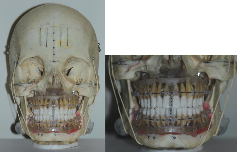
The clear plastic bases of the maxilla and the mandible were modified to allow access to the root apices of each tooth. Stainless steel balls (Small Parts, Miramar, Fla), 1.58 mm in diameter, were fixed to indentations created with a number 2 round bur at the following locations: (1) the approximate mesiodistal and buccolingual center of the occlusal surface of each tooth, and (2)the approximate center of the root apex for teeth with a single root or the center of the bifurcation or trifurcation at the level of the root apices for multi-rooted teeth.
A 0.51-mm round stainless steel archwire (3M Unitek, Monrova, Calif) was positioned on the plastic mold of both the maxilla and the mandible at approximately the middle of the roots, spanning the dentition from second molar to second molar. The wires were placed in this position, rather than on the clinical crown of the tooth, to prevent overlapping the occlusal steel balls on the typodont teeth as they were projected on the CBCT pan-like image. The wires were held in place with Transbond XT light-cured adhesive (3M Unitek) secured to the plastic mold by using tubular indentations approximately 5 mm deep and 3 mm in diameter created with a number 2 roundbur.
The 1.58-mm steel balls on the typodont teeth were used as radiopaque markers for measurement purposes on the CBCT pan-like images. A line connecting the center of the occlusal and apical steel balls on each tooth was used to represent its long axis. The image reconstruction from the CBCT data was oriented parallel to the maxillary or mandibular archwire when measuring the maxillary or mandibular teeth, respectively, on the CBCT pan-like image.
A coordinate measuring machine (CMM) (Faro International, Lake Mary, Fla) was used to determine the actual mesiodistal angular measurement of each tooth with reference to the archwire. The CMM was reported by the manufacturer to be accurate to within 0.013 mm. For verification of its accuracy, a test was done on an object known to have a 90° angle between 2 sides. The machine was found to be accurate to within 0.031°. Before being secured in the skull, each typodont was fixed to a surveyor table to prevent movement and then measured as follows.
First, a horizontal plane was created separately for each typodont (maxilla and mandible). This was performed by touching the external point probe of the CMM to the most superior surface of the maxillary or mandibular archwire at 6 locations spread out along the wire.
Second, a vertical plane was created for each tooth that was perpendicular to the horizontal (archwire) plane explained above. This was performed by touching the CMM probe to the most distal position on the crimpable archwire stop located on the archwire immediately mesial to a tooth, and to the most mesial position on the stop located on the archwire immediately distal to a tooth. A custom-designed feature (Computer Science Engineering, University of Alberta) added to the CMM was used to create a plane connecting these 2 points that was perpendicular to the plane created by the archwire. This plane was used as a reference to measure the mesiodistal angle of each tooth.
Third, the steel balls on the apical and occlusal surfaces of each tooth were measured by touching the CMM probe to 4 positions on each ball. The CMM software used these four 3D positions ([x 1 , y 1 , z 1 ], [x 2 , y 2 , z 2 ], [x 3 , y 3 , z 3 ], and [x 4 , y 4 , z 4 ]) to create a digital representation of each sphere. The CMM software was then used to create a line connecting the center of the apical and occlusal sphere on each tooth.
The angle between this line and the horizontal plane created by the archwire, projected onto the vertical plane created by using the archwire stops in the second step represented the mesiodistal angulation of the tooth. The smallest angle was used (whether it was mesial or distal) to compare with the angle from the CBCT pan-like image ( Fig 2 ).
The principal investigator (D.V.E.) made the measurements on 5 separate occasions, 5 days apart, and the ICC values were calculated to determine the reliability of the measurements.
To scan the skull with the CBCT NewTom 3G volume scanner (AFP, Elmsford, NY), the skull was placed into an acrylic plastic box containing 2 lateral slots filled with water and placed on the patient table for scanning. The water in the glass box simulated the attenuation of soft tissues in a clinical situation and was necessary for the CBCT scan. The skull was positioned according to the manufacturer’s instructions so that the upper laser divided the skull into 2 identical halves, and the lateral laser was positioned on the center of the area of interest, which in this case was the center of thecrown of the mandibular right second molar. The initial position assessment of the NewTom software verified the proper placement. If the mandible and maxilla were both centered in the innermost grid of the 0° and 90° scout views, the scan proceeded.
The settings for the scan were as follows: 110kV, 0.90 mA, 1.20 kV, 1.20 mA, 9-in detector field, 7.2-second exposure time, and 7.20 mAs. These settings, with the exception of the detector field, were predetermined by the software and similar to what would be applied in a clinical situation. A 9-in (medium) field of view was selected for the 3D scan to localize the field of view to an area slightly larger than the maxilla and the mandible. The primary reconstruction of the raw data was completed with high resolution (0.2-mm voxel size) and a small field size to provide the best mix between image noise and higher resolution.
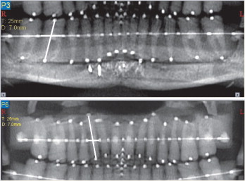
Using the NewTom software, a study reconstruction was taken from the volumetric data set slice with the axial slice thickness for the reconstruction set at 0.3 mm. An axial image was selected so that it was parallel to the maxillary and mandibular archwires. The secondary reconstruction to create the pan-like image was performed by setting the image thickness at 25 mm, with 7 mm between each image. The points for the path were (1) the most inferior and central position of the posterior part of the mandibular ramus, (2) the most superior and central position of the anterior part of the mandibular ramus, and (3) at the mesial and distal edges of each stop along the maxillary or mandibular archwire.
The software produces 3 pan-like images based on the path selection. The image running along the approximate buccolingual center of the occlusal surface of the teeth was chosen (third or innermost pan trough), and saved as a jpeg file.
A custom software tool to measure 4 point angulations on jpeg files was developed by using MATLAB software (The MathWorks, Natick, Mass). It was used to take measurements of each jpeg file with lines previously defined. The software measurements were also compared with hand measurements; the software was determined to be superior in accuracy.
Statistical analysis
The traditional α of 0.05 was divided by the number of comparisons, which in this case was the number of teeth (28). Therefore, significance levels were set at 0.001786 (0.05/28). For multiple tests, the significance level was adjusted according to the Bonferroni correction to keep the overall type 1 error rate α = 0.05.
According to the statistical literature, to achieve a power of 0.8 with a large effect size (0.8), between 20 and 30 samples were required for the study. A retro-active analysis was done to clarify the appropriate sample size for the study by using the data gathered for the study. Based on the results calculated with Mini-tab 15 software (State College, Pa), an average of 107 images were required for a power of 0.9; 997 was the largest sample size needed for tooth 37 (FDI numbering system). Twenty-five images, rather than 107, were used for the data set because the measurements were determined to be reliable, and the study was done with 1 skull; therefore, more than 25 images would have nobenefit.
Using 1 skull helped control for confounding variables, which for this study included the many steps required to process the volumetric data of the scan to create a CBCT pan-like image.
To look for a statistically significant difference between the CMM mesiodistal tooth angulations and those measured from the pan-like images, a matched-pairs t test was done on the data with SPSS software (SPSS, Chicago, Ill).
Results
Reliability analyses by using the ICC were carried out to assess the reliability of mesiodistal angular measurements with the CMM on the typodont teeth and the MATLAB software on the pan-like images. To test the CMM, measurements for each tooth on the typodont were taken on 5 separate occasions, 5 days apart; 0.95 was used for the cutoff to determine the ICC. The ICC for absolute agreement of CMM measurements was calculated as 0.995 with a 95% CI of 0.991 to 0.997. Therefore, the mesiodistal angular measurements taken with the CMM had high reliability.
For the reliability of the angular measurements made with the MATLAB on the pan-like images, 2 images were selected, and 11 teeth were randomly chosen from both arches to represent a range of measurements. The primary operator (D.V.E.) measured the mesiodistal angles of the 11 teeth on both pan-like images on 3 occasions, 5 days apart. The ICC for absolute agreement of image measurements was calculated to be 0.995 with a 95% confidence interval of 0.989 to 0.998. Therefore, the measurements of mesio-distal angles projected on the pan-like images with the MATLAB had high reliability.
The results of the matched-pairs t test comparing the CMM and CBCT pan-like image angles for each tooth are shown in the Table , including the mean differences, standard deviations, 95% confidence intervals, and significances. Statistically significant differences were found between the CMM and the CBCT pan-like image angles for the following teeth: 16, 15, 12, 13, 21, 22, 23, 24, 26, 47, 44, 41, 32, 33, 34, and 36 ( P <0.001, α = 0.001786).


