Mechanical Principles in Orthodontic Force Control
ELASTIC MATERIALS AND THE PRODUCTION OF ORTHODONTIC FORCE
The Basic Properties of Elastic Materials
Orthodontic Archwire Materials
DESIGN FACTORS IN ORTHODONTIC APPLIANCES
Two-Point Contact for Control of Root Position
Elastic Materials and the Production of Orthodontic Force
The Basic Properties of Elastic Materials
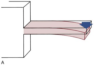
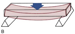
For analysis, orthodontic archwires and springs can be considered as beams, supported either only on one end (e.g., a spring projecting from a removable appliance) or on both ends (the segment of an archwire spanning between attachments on adjacent teeth) (Figure 9-1). If a force is applied to such a beam, its response can be measured as the deflection (bending or twisting) produced by the force (Figure 9-2). Force and deflection are external measurements. Internal stress and strain can be calculated from force and deflection by considering the area and length of the beam.
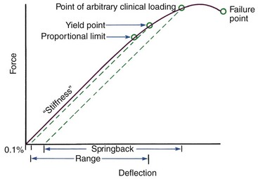
For orthodontic purposes, three major properties of beam materials are critical in defining their clinical usefulness: strength, stiffness (or its inverse, springiness), and range. Each can be defined by appropriate reference to a force–deflection or stress–strain diagram (Figures 9-2 and 9-3).
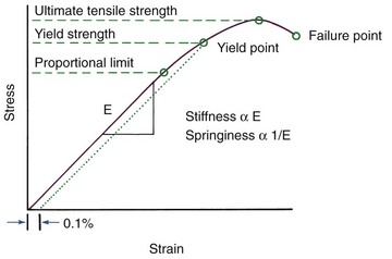
Three different points on a stress–strain diagram can be taken as representative of the strength of a material (see Figure 9-3). Each represents, in a somewhat different way, the maximum load that the material can resist. The first two points attempt to describe the elastic limit of the material, the point at which any permanent deformation is first observed. The most conservative measure is the proportional limit, the highest point where stress and strain still have a linear relationship (this linear relationship is known as Hooke’s law). Precisely determining this point can be difficult, so a more practical indicator is the yield strength—the intersection of the stress–strain curve with a parallel line offset at 0.1% strain. Typically, the true elastic limit lies between these two points, but both serve as good estimates of how much force or deflection a wire can withstand clinically before permanent deformation occurs. The maximum load the wire can sustain—the ultimate tensile strength—is reached after some permanent deformation and is greater than the yield strength. Since this ultimate strength determines the maximum force the wire can deliver if used as a spring, it also is important clinically, especially since yield strength and ultimate strength differ much more for the newer titanium alloys than for steel wires.
Stiffness and springiness are reciprocal properties:

Each is proportional to the slope of the elastic portion of the force–deflection curve (see Figure 9-2). The more horizontal the slope, the springier the wire; the more vertical the slope, the stiffer the wire.
Range is defined as the distance that the wire will bend elastically before permanent deformation occurs. For orthodontics, this distance is measured in millimeters (see Figure 9-2). If the wire is deflected beyond this point, it will not return to its original shape, but clinically useful springback will occur unless the failure point is reached. This springback is measured along the horizontal axis as shown in Figure 9-2. Orthodontic wires often are deformed beyond their elastic limit, so springback properties are important in determining clinical performance.
These three major properties have an important relationship:

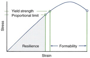
Two other characteristics of some clinical importance also can be illustrated with a stress–strain diagram: resilience and formability (Figure 9-4). Resilience is the area under the stress–strain curve out to the proportional limit. It represents the energy storage capacity of the wire, which is a combination of strength and springiness. Formability is the amount of permanent deformation that a wire can withstand before failing. It represents the amount of permanent bending the wire will tolerate (while being formed into a clinically useful spring, for instance) before it breaks.
Orthodontic Archwire Materials
In the first half of the twentieth century, precious metal alloys were used routinely for orthodontic purposes, primarily because nothing else would tolerate intraoral conditions. Gold itself is too soft for nearly all dental purposes, but alloys (which often included platinum and palladium along with gold and copper) could be useful orthodontically. The introduction of stainless steel made precious metal alloys obsolete for orthodontic purposes even before precious metals became prohibitively expensive. Currently, the only considerable advantage to gold is the ease of fabricating cast appliances, such as custom-fit bonding pads used with fixed lingual appliances (see Chapter 10).
Nickel–Titanium Alloys
Properties of Nickel–Titanium Alloys: Archwires formed from nickel–titanium alloys are extremely useful during initial orthodontic alignment due to their exceptional ability to apply light force over a large range of activations. The first nickel–titanium alloy was developed for the space program and named nitinol (Ni, nickel; Ti, titanium; NOL, Naval Ordnance Laboratory). In this book, the term NiTi is used subsequently to refer to the family of nickel–titanium wire materials (nitinol, with the word not capitalized, is used in the same way in some other publications). Reference to a specific material is by its trademark (capitalized) name.
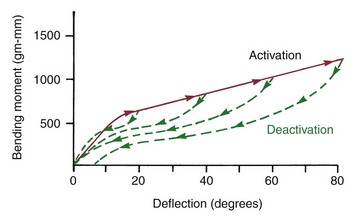
Superelasticity refers to the very large reversible strains that certain NiTi wires can withstand due to the martensite-austenite phase transition. In engineering applications, it also is frequently described as pseudoelasticity, due to the nonlinear stress–strain curve, which is not typical of elastic behavior (Figure 9-5). Materials displaying superelasticity are austenitic alloys that undergo a transition to martensite in response to stress—a mechanical analogue to the thermally induced shape memory effect. This is possible because the transition temperature is very close to room temperature. Most archwire materials can be reversibly deformed only by stretching interatomic bonds (which creates the linear region of the stress–strain curve), while superelastic materials can undergo a reversible change in internal structure after a certain amount of deformation. This stress-induced martensitic transformation manifests itself in the almost flat section of the load-deflection curve. This means that an initial archwire could exert about the same force whether it was deflected a relatively small or large distance, which is a unique and extremely desirable characteristic (Figure 9-6). For a change, superelasticity is not just another advertising term.
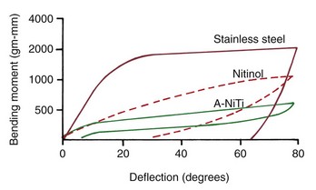
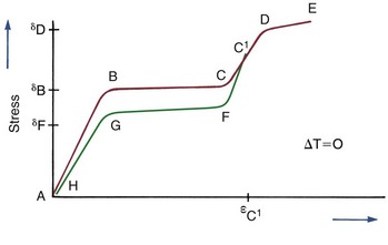
FIGURE 9-6 A stress–strain curve illustrating superelasticity due to the stress-induced transformation from the austenitic to the martensitic phase, as in an A-NiTi archwire. Section A-B represents purely elastic deformation of the austenitic phase (note in Figure 9-5 that in this phase A-NiTi is stiffer than M-NiTi). The stress corresponding to point B is the minimum stress at which transformation to the martensitic phase starts to occur. At point C, the transformation is completed. The difference between the slopes of A-B and B-C indicates the ease with which transformation occurs. After the transformation is completed, the martensitic structure deforms elastically, represented by section C-D (but orthodontic archwires are almost never stressed into this region, and this part of the graph usually is not seen in illustrations of the response of orthodontic archwires). At point D, the yield stress of the martensitic phase is reached, and the material deforms plastically until failure occurs at E. If the stress is released before reaching point D (as at point C1 in the diagram), elastic unloading of the martensitic structure occurs along the line C1-F. Point F indicates the maximum stress on which the stress-induced martensitic structure on unloading can exist, and at that point the reverse transformation to austenite begins, continuing to point G, where the austenitic structure is completely restored. G-H represents the elastic unloading of the austenite phase. A small portion of the total strain may not be recovered because of irreversible changes during loading or unloading.
NiTi Wires in Clinical Orthodontics: The original Nitinol wires marketed under that name in the late 1970s by Unitek were M-NiTi wires, with no application of phase transition effects. As supplied for orthodontic use, Nitinol is exceptionally springy and quite strong but has poor formability (Table 9-1). In the late 1980s, new nickel–titanium wires with an austenitic grain structure (A-NiTi) appeared. These wires (Sentinol, GAC; Copper NiTi, Ormco/Sybron; and several other suppliers) exhibit superelasticity and/or shape memory in various degrees. Without laboratory data, however, it is dangerous to assume that wires advertised as superelastic really are,1 so care in purchasing is advised. Data for performance under controlled conditions, not testimonials from prominent clinicians, should be the basis for choosing a specific wire.
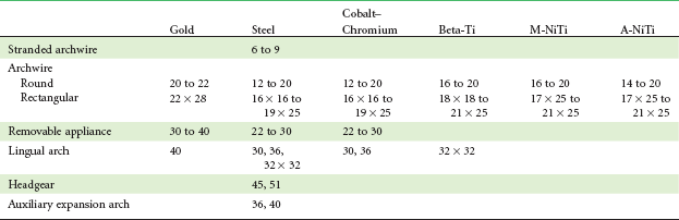
TABLE 9-1
Comparative Properties of Orthodontic Wires
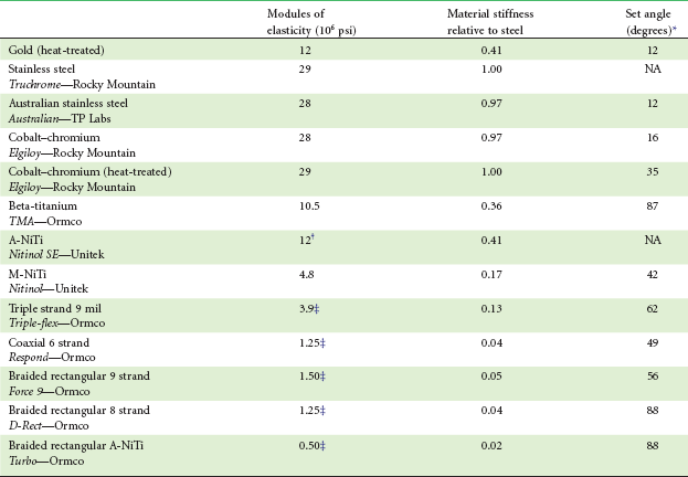
*Degrees of bending around  -inch radius before permanent deformation.
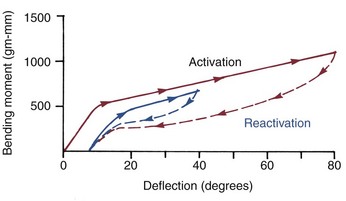
Part of the unusual nature of a superelastic material like A-NiTi is that its unloading curve differs from its loading curve (i.e., the reversibility has an energy loss associated with it [hysteresis]) (Figure 9-7). This means the force that it delivers is not the same as the force applied to activate it. The different loading and unloading curves produce the even more remarkable effect that the force delivered by an A-NiTi wire can be changed during clinical use merely by releasing and retying it (Figure 9-8).
For the orthodontist, wire bending in the classic sense is all but impossible with A-NiTi wires because they do not undergo plastic deformation until remarkably deformed (see Figure 9-5). The wires can be shaped and their properties can be altered, however, by heat treatment. This can be done in the orthodontic office by passing an electric current between electrodes attached to the wire or a segment of it. Miura et al were the first to show that it is possible to reposition the teeth on a dental cast to the desired posttreatment occlusion, bond brackets to the setup, force an A-NiTi wire into the brackets, and then heat treat the wire so that it “memorizes” its shape with the teeth in the desired position.2 The wire then incorporates all of what would otherwise be the “finishing bends” usually required in the last stages of treatment. In theory at least, this allows certain types of treatment to be accomplished with a single wire, progressively bringing the teeth toward their predetermined position. The concept is exactly the same as Edward Angle’s original approach to arch expansion, which implies that the same limitations would be encountered. At present, however, this approach is used primarily in computer-assisted fabrication of the initial archwires for lingual orthodontics (see later section in this chapter), and there is no attempt to do everything with one archwire.
Beta-Titanium
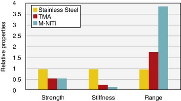
Strength, stiffness, and range for stainless steel, beta-Ti, and M-NiTi wires are compared in Figure 9-9 (also see Table 9-1 for other comparative data). Note that in many ways the properties of beta-Ti are intermediate between stainless steel and M-NiTi.
Composite Plastics
Additional progress in orthodontic elastic materials is occurring in the early twenty-first century. The new orthodontic materials of recent years have been adapted from those used in aerospace technology. The high-performance aircraft of the 1980s and 1990s were titanium-based, but their replacements are being built (with some difficulty) of composite plastics (e.g., Boeing’s much-delayed 787). Orthodontic technology tends to trail aerospace technology by 15 to 20 years, and orthodontic “wires” of composite materials have been shown in the laboratory to have desirable properties3 but have not yet come into clinical use. It was more than a decade before the first NiTi wires went from clinical curiosity to regular use, and a similar time period may be needed to bring the composite plastics into routine clinical orthodontics.
Comparison of Contemporary Archwires
As we have noted previously, stainless steel, beta-Ti, and NiTi archwires all have an important place in contemporary orthodontic practice. Their comparative properties explain why specific wires are preferred for specific clinical applications (see Chapters 14 through 18). Hooke’s law (which defines the elastic behavior of materials and is illustrated in Figures 9-2, 9-3, and 9-4) applies to all orthodontic wires except superelastic A-NiTi. For everything else, a useful method for comparing two archwires of various materials, sizes, and dimensions is the use of ratios of the major properties (strength, stiffness, and range):


These ratios were calculated for many different wires by the late Robert Kusy,4 and the data presented here are taken from his work. When the comparative properties of wires are considered, it is important to keep two things in mind:
1. Bending describes round wires reasonably completely in orthodontic applications, but both bending and torsional stresses are encountered when rectangular wires are placed into rectangular attachments on teeth. The fundamental relationships for torsion are analogous to those in bending but are not the same. Appropriate use of the equations for torsion, however, allows torsion ratios to be computed in the same way as bending ratios.
2. The ratios apply to the linear portion of the load-deflection curve and thus do not accurately describe the behavior of wires that are stressed beyond their elastic limit but still have useful springback. This is an increasingly significant limitation as consideration passes from steel or chromium–cobalt to beta-Ti to M-NiTi. The nonlinear response of A-NiTi makes calculation of ratios for it all but impossible. Nevertheless, the ratios offer an initial understanding of the properties of traditional steel wires as compared with the newer titanium alloys, and they can be quite helpful in appreciating the effects of changing wire size and geometry in a typical archwire sequence.
The most efficient method for comparing different wire materials and sizes (within the limitations described above) is the use of nomograms—fixed charts that display mathematical relationships via appropriately adjusted scales. In the preparation of a nomogram, a reference wire is given a value of 1, and many other wires can then be located appropriately in reference to it. Nomograms developed by Kusy to provide generalized comparisons of stainless steel, M-NiTi, and beta-Ti in bending and torsion are shown in Figures 9-10 and 9-11. Note that because the nomograms of each set are all drawn to the same base, wires of different materials, as well as different sizes, can be compared.
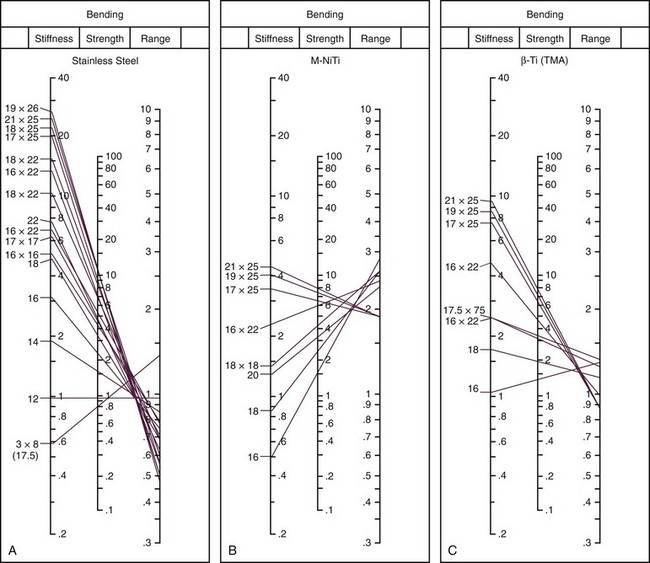
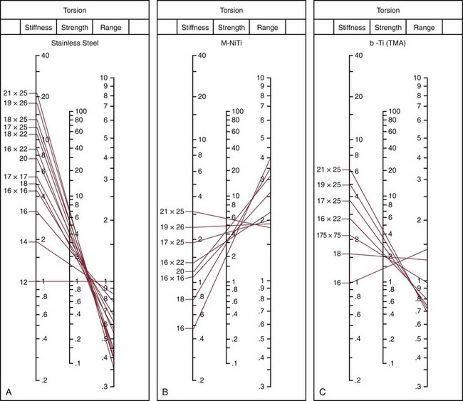
The nomograms are particularly helpful in allowing one to assess at a glance a whole set of relationships that would require pages of tables. For example, let’s use Figure 9-11 to compare 21 × 25 M-NiTi to 21 × 25 beta-Ti in torsion (the appropriate comparison if the wires would be used to produce a torquing movement of the root of a tooth). 21 × 25 beta-Ti has a torsional stiffness value of 6, while 21 × 25 M-NiTi has a value of 3, so the beta-Ti wire would deliver twice the force at a given deflection; the strength value for 21 × 25 beta-Ti wire is 4, while the value for this size M-NiTi wire is 6, so the NiTi wire is less likely to become permanently distorted if twisted into a bracket; the range value for 21 × 25 beta-Ti is 0.7, while the same size M-NiTi has a range value of 1.9, so the NiTi could be twisted nearly three times as far. The nomograms contain the information to allow a similar comparison of any one of the wire sizes listed to any other wire shown on the chart, in bending (see Figure 9-10) or torsion (see Figure 9-11).
Effects on Elastic Properties of Beams
Geometry: Size and Shape
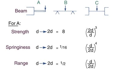
Cantilever Beams: Let us begin by considering a cantilever beam supported on only one end. In orthodontic applications, this is the type of spring often used in removable appliances, in which a wire extends from the plastic body of the removable appliance as a fingerspring. When a round wire is used as a fingerspring, doubling the diameter of the wire increases its strength eight times (i.e., the larger wire can resist eight times as much force before permanently deforming or can deliver eight times as much force). Doubling the diameter, however, decreases springiness by a factor of 16 and decreases range by a factor of two.
More generally, for a round cantilever beam, the strength of the beam changes as the third power of the ratio of the larger to the smaller beam; springiness changes as the fourth power of the ratio of the smaller to the larger; and range changes directly as the ratio of the smaller to the larger (Figure 9-12).
 as springy and has half the range. More generally, when beams of any type made from two sizes of wire are compared, strength changes as a cubic function of the ratio of the two cross-sections; springiness changes as the fourth power of the ratios; range changes as a direct proportion (but the precise ratios are different from those for cantilever beams).
Supported Beams: The situation is somewhat more complex for a beam supported on both ends, as is the case for a segment of archwire between two teeth. Supporting both ends makes the beam stronger and less flexible, particularly if the ends are tightly anchored as opposed to being free to slide. If a rectangular beam is evaluated, its dimension in the direction of bending is the primary determinant of its properties. The principle with any supported beam, however, is the same as with a cantilever beam: as the beam size increases, strength increases as a cubic function, while springiness decreases as a fourth power function and range decreases proportionately, not exponentially.
As the diameter of a wire decreases, its strength decreases so rapidly that a point is reached at which the strength is no longer adequate for orthodontic purposes. As the diameter increases, its stiffness increases so rapidly that a point is reached at which the wire is simply too stiff to be useful. These upper and lower limits establish the wire sizes useful in orthodontics. The phenomenon is the same for any material, but the useful sizes vary considerably from one material to another. As Table 9-2 indicates, useful steel wires are considerably smaller than the gold wires they replaced. The titanium wires are much springier than steel wires of equal sizes but not as strong. Their useful sizes therefore are larger than steel and quite close to the sizes for gold.
Geometry: Length and Attachment
Changing the length of a beam, whatever its size or the material from which it is made, also dramatically affects its properties (Figure 9-13). If the length of a cantilever beam is doubled, its bending strength is cut in half, but its springiness increases eight times and its range four times. More generally, when the length of a cantilever beam increases, its strength decreases proportionately, while its springiness increases as the cubic function of the ratio of the length and its range increases as the square of the ratio of the length. Length changes affect torsion quite differently from bending: springiness and range in torsion increase proportionally with length, while torsional strength is not affected by length.
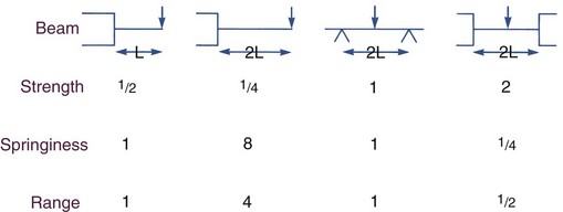
The way in which a beam is attached also affects its properties. An archwire can be tied tightly or loosely, and the point of loading can be any point along the span. As Figure 9-12 shows, a supported beam like an archwire is four times as springy if it can slide over the abutments (in clinical use, through a bracket into which it is loosely tied) rather than if the beam is firmly attached (tied tightly). With multiple attachments, as with an archwire tied to several teeth, the gain in springiness from loose ties of an initial archwire is less dramatic but still significant.5
Controlling Orthodontic Force by Varying Materials and Size–Shape of Archwires
In practice, this lengthening often means doubling the wire back on itself or winding a helix into it to gain length while keeping the spring within a confined intraoral area (Figure 9-14). The same technique can be used with archwires, of course; the effective length of a beam is measured along the wire from one support to the other, and this does not have to be in a straight line (Figure 9-15). Bending loops in archwires can be a time-consuming chairside procedure, which is the major disadvantage.
Another way to obtain a better combination of springiness and strength is to combine two or more strands of a small and therefore springy wire. Two 10 mil steel wires in tandem, for instance, could withstand twice the load as a single strand before permanently deforming, but if each strand could bend without being restrained by the other, springiness would not be affected. The genesis of the “twin wire” appliance system (see Chapter 10) was just this observation: that a pair of 10 mil steel wires offered excellent springiness and range for aligning teeth and that two wires gave adequate strength, although one did not. Later, three or more strands of smaller steel wires, twisted into a cable, came into common use (see Figure 9-15). The properties of the multistrand wire depend both on the characteristics of the individual wire strands and on how tightly they have been woven together. Multistrand steel wires offer an impressive combination of strength and spring qualities but now have been displaced for most applications by NiTi wires.
The exceptional springiness of A-NiTi makes it a particularly attractive alternative to steel wires in the initial phases of treatment when the teeth are severely malaligned. A continuous NiTi archwire of either type will have better properties than multistrand steel wires and properties similar to a steel archwire with loops. TMA, as an intermediate between NiTi and steel, is less useful than either in the first stage of full-appliance treatment. Its excellent overall properties, however, make it quite useful in the later stages of treatment. It is possible and frequently desirable to carry out orthodontic treatment with a series of wires of approximately the same size, using a sequence from NiTi to TMA to steel. Archwire selection in varying circumstances is discussed in more detail later in this chapter and in Chapters 14 to 16.
Other Sources of Elastic Force
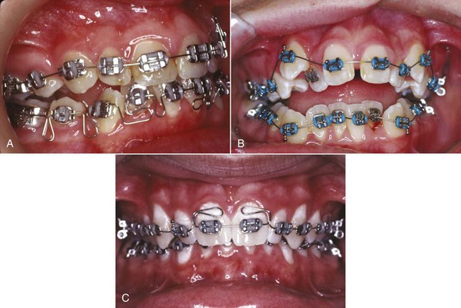
Elastomeric plastics for orthodontic purposes are marketed under a variety of trade names. Small elastomeric modules replace wire ligature ties to hold archwires in the brackets in many applications (see Figure 9-15, B) and also can be used to apply a force to close spaces within the arches. Like rubber, however, these elastomers tend to deteriorate in elastic performance after a relatively short period in the mouth. This feature does not prevent them from performing quite well in holding archwires in place nor does it contraindicate their use to close small spaces. It simply must be kept in mind that when elastomers are used to move teeth, the forces decay rapidly and so can be characterized better as interrupted rather than continuous.6 Although larger spaces within the dental arch can be closed by sliding teeth with rubber bands or elastomeric chains, the same tooth movement can be done much more efficiently with A-NiTi springs that provide a nearly constant force over quite a large range.
Magnets
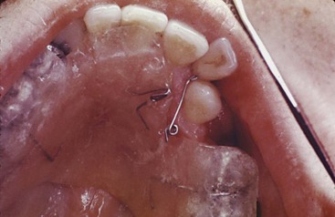
Magnets in attraction or repulsion could generate forces of the magnitude needed to move teeth and would have the advantage of providing predictable force levels without direct contact or friction. Until rare earth magnets were developed in the 1980s, magnetic devices with enough force at reasonable separation distances were simply too bulky for orthodontic purposes. In the 1990s, with smaller and more powerful magnets available, there was considerable interest in the possibility of using magnetic force in orthodontics (Figure 9-16).
The two key questions with magnets as a source of force are their biologic implications and their clinical effectiveness.7 Although rare earth materials are potentially toxic, direct cytotoxic effects have not been observed when magnets in sealed cases are placed intraorally. If a magnetic field increased the rate of bone remodeling and tooth movement, this would be a compelling reason to use magnets, but careful research has shown little if any biologic effect from the small magnets used to generate orthodontic force. Although safety is not a problem,8 the force between a pair of magnets follows the inverse square law (i.e., the force changes as the square of the distance between the magnets), so when magnets provide the force to move teeth, the force levels quickly become too small or too large as soon as teeth begin to move. This major disadvantage makes it unlikely that magnetic force will become an important part of orthodontic treatment, and magnets have largely disappeared from contemporary treatment.
Stay updated, free dental videos. Join our Telegram channel
VIDEdental - Online dental courses


