7
Appliance Design
Introduction
Definition of the necessary force system
Anchorage evaluation
Sequencing the treatment into phases
Anchorage
Generation of space
Mandibular position
Appliance selection and design
Removable appliances
Fixed appliances
Sliding mechanics
Resistance to sliding
Statically determinate and indeterminate force systems
Continuous archwires
Segmented mechanics
Loops
The use of power-arms
Easy or difficult tooth movement
Cantilevers
Two-vector mechanics
Conclusion
References
Introduction
When selecting the appliance for orthodontic treatment of adult patients, it is important to recognize the limitations caused by general or local loss of periodontium due to missing teeth and prosthetic replacements which have to be maintained. The lack of influence of growth conversely allows a more precise prediction of the treatment result, as the tooth movements reflect the applied force systems more closely. The direction and location of the line of action of the applied force determines how and in which direction the individual tooth or groups of teeth will move. The only factors that influence the treatment result are the soft tissue matrix, the balance between the internal and the external muscle matrices and the occlusal forces.
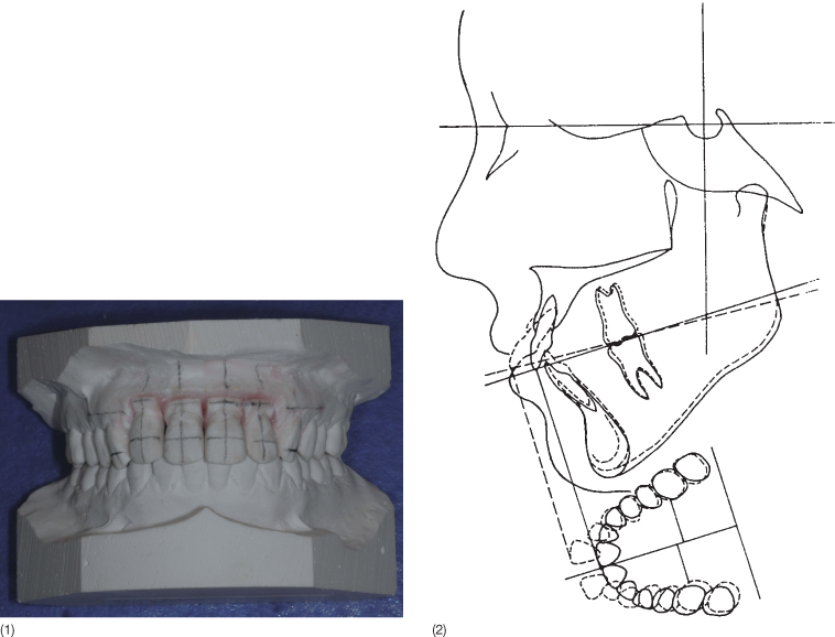
In the adult patient, a detailed planning of the necessary tooth movements in all three planes of space can be done on a diagnostic set-up of study casts (Fig. 7.1), a combination of a tracing of a head film and occlusogram (Fig. 7.1) or a set-up on virtual models generated either from a scan performed intraorally, scanned impressions or study casts (Mah and Sachdeva 2001; Sachdeva 2001; Santoro et al. 2001; Vlaskalic and Boyd 2002; Freshwater 2003; Joffe 2003; Santoro et al. 2003; Zilberman et al. 2003; Joffe 2004; Dalstra and Melsen 2009). The set-up is frequently done by orthodontic companies with only minimal interaction with the orthodontist and without detailed information about how the final occlusion will be achieved. The treatment plan and appliance design are not separable, since the prescription or even the appliance is provided with the set-up. The orthodontist aims for a good occlusion without knowing how the individual teeth will achieve their final position. An analogy would be: ‘I wish to spend my vacation in the snow but I do not know whether the travel agency has sent me to Mount Cook or to Mont Blanc’. The set-up, whether real or virtual, should include information about the movement of each tooth or group of teeth in all three planes of space. If the combination of a head film and an occlusogram or a virtual model is used, the tooth movements can be visualized in all three planes. For a more detailed description, see Chapter 5. In relation to movement of teeth on virtual models, the coordinates should indicate the displacement.
Fig. 7.1 (1) A set-up made from study casts. Note the grid drawn before the teeth are moved. This allows the dentist to appreciate the exact movement performed on the set-up. In this case the upper incisors have been intruded and retracted. (2) Treatment goal illustrated on a combination of an occlusogram and a tracing of the head film. The flaring and spacing of the upper incisors will be corrected by retraction of the four incisors without major movements of other teeth.
Definition of the Necessary Force System
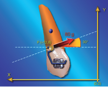
A force acting on a tooth can be represented as a vector defined in relation to a given coordinate system by its magnitude, its point and line of application as well as its direction and orientation (Fig. 7.2).
Fig. 7.2 The force can be described as a vector in a coordinate system. Four parameters are necessary to define a force: the magnitude is indicated by the length of a vector in a coordinate system with an arbitrary scale. The point of force application and the angle of incidence define the line of action of the force. The orientation of the arrowhead indicates its direction, thereby completing the force definition.
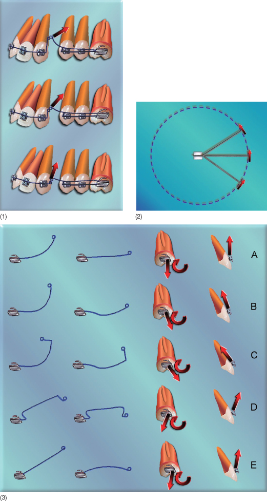
Tooth movements can be translations, rotations or various combinations of translation and rotation. According to the line of action of the force vector, Hocevar (1981, 1987) defined four types of horizontal tooth movement in the sagittal plane (Fig. 7.3). A force passing through the bracket results in uncontrolled tipping. When the force passes halfway between the centre of resistance (CR) of the tooth and the bracket, the resulting movement is a so-called controlled tipping with the centre of rotation close to the tooth apex. A force passing through the CR generates translation and further apical displacement of the line of action of the force leads to root movement with the centre of rotation close to the incisal edge. Similar classifications of tooth movement can be made in other planes of space (Christiansen and Burstone 1969; Kusy and Tulloch 1986). Application of the correct line of action is a pre-condition for well-controlled tooth movement. In cases in which the major part of the planned tooth movement will occur in one plane of space, it may be sufficient to define the line of action in that particular plane of space (Figure 7.4).
Fig. 7.3 (1) The four types of movement as defined by Hocevar (1981), with the corresponding line of action of the force. (2) Same classification but with the force system defined with respect to the bracket.
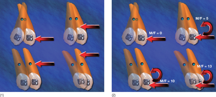
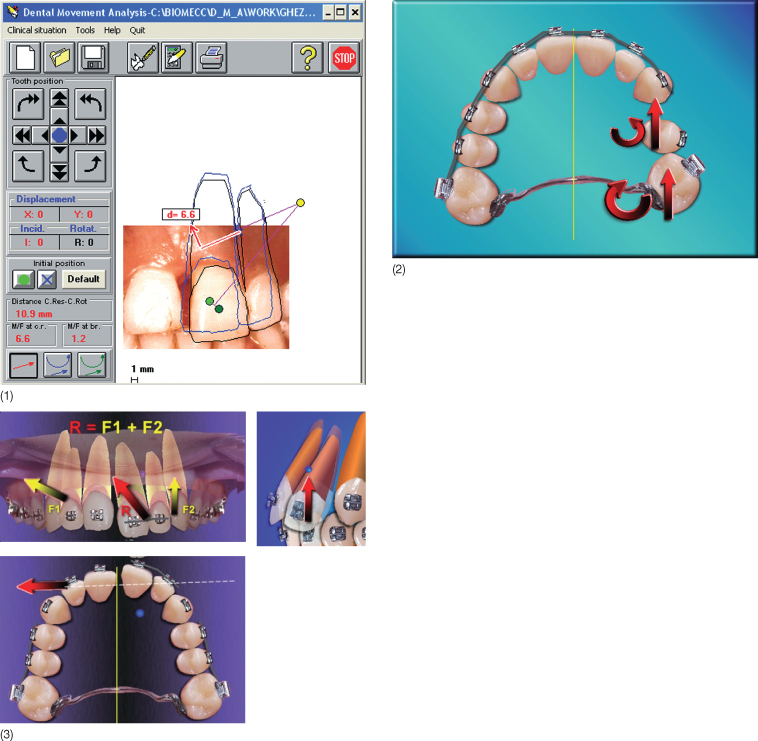
Fig. 7.4 (1) Displacement of incisors in the frontal plane, simulated by the Dental Movement Analysis software. In this example, the software simulates movement of teeth 21 and 22 as a single unit in two dimensions. The yellow circle is the desired centre of rotation. The red arrows represent the single force that should be applied in order to obtain the displayed movement. (2) A situation where only tooth movements in the horizontal plane are needed. (3) Three-dimensional analysis of a force system. Two different vectors (F1 and F2) are applied and the resultant force (R) is shown in the frontal, occlusal and sagittal planes, as is the estimated position of the centre of resistance of the active unit. This type of analysis allows a detailed prediction of dental movement.
The localization of the line of action in relation to the CR of the tooth or of the group of anchor teeth will determine the relative contribution of translation and rotation to the total movement, and thus determine the centre of rotation for the total movement (Fig. 7.5). The perpendicular distance from the CR to the line of action expresses the moment-to-force ratio with respect to the CR, thus the relative amount of rotation and translation of the movement. A change in the moment-to-force ratio can be obtained by displacement of the point of force application or by adding a moment to the bracket (Fig. 7.6).
Fig. 7.5 The incisor movement from the clear to the shaded image is translation (given by the distance and the direction) combined with rotation expressed as an angle and a line of direction. The total movement, however, can also be expressed by the localization of the centre of rotation for the total movement and the degree of rotation. The movement will be the result of a force in the same direction as the displacement of the centre of resistance (CR) and applied above the CR. As the distance from the line of action to the CR will increase once rotation starts, the relative component of the movement made up of rotation increases.
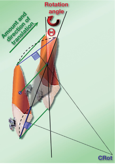
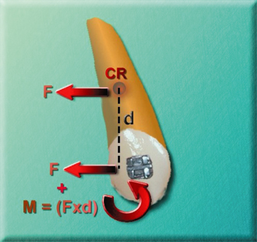
Fig. 7.6 Translation can be achieved by a force passing through the centre of resistance (CR) in the direction of the desired translation or by adding a force to the bracket in addition to a moment neutralizing the moment generated by the force acting at a distance from the CR. This moment-to-force ratio is called the replacement force system.
According to the laws of physics for each tooth movement, there is one correct line of action. However, the same line of action can be generated by a multiplicity of appliances. To facilitate the estimation of the force system needed for a specific movement, a computer program, Dental Movement Analysis (DMA), was developed in the early 1990s. Based on relations between the localization of the centre of rotation and the applied force system (Burstone and Pryputniewicz 1980; Burstone 1991) DMA can simulate any dental movement and visualize the line of action needed with respect to either the bracket or the CR (Fiorelli and Melsen 1999; Fiorelli and Melsen 2000).
The type of tooth movement can be controlled by varying the moment-to-force ratio to the CR. Holographic analysis and radiographic and clinical examinations have been used to estimate the position of the CR (Burstone and Pryputniewicz 1980). Local constraints from soft tissue function and differences in the quality of the alveolar bone do, however, also influence the resistance to tooth movement and differences in force level may consequently effect the localization of the CR (Cattaneo 2003).
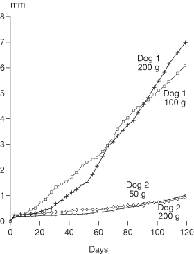
While the type of tooth movement in the main reflects the force system, the rate of tooth movement seems to be under genetic control; variation in force levels does not seem to influence the rate of dental movement (Pilon et al. 1996; van Leeuwen et al. 1999; Ren et al. 2004) (Fig. 7.7). The optimal force system cannot be stated, but with the introduction of superelastic wires a trend towards lower force levels has been noted. However, the initial force level is still high (Fuck and Drescher 2006).
Fig. 7.7 The rate of tooth movement in two dogs: the rate is determined more by the individual dog than the force level.
(With permission from Pilon et al. (1996).)
In spite of the apparent need for control of the force system, it is more the exception than the rule that force systems are seriously considered when inserting an orthodontic appliance. Despite this, there is a high success rate, which can be ascribed to interaction of the forces generated by orthodontic appliances with growth, occlusal forces, and a balance between the external and the internal muscle matrices. In the adult patient, the absence of growth in the vertical dimension increases the risk of undesirable movements and iatrogenic damage. Careful planning of the applied force system is therefore recommended.
Anchorage Evaluation
When the desired tooth movements have been identified and the necessary force systems for delivering these defined, the reactive forces acting on the anchorage unit should be evaluated. There are cases that do not present any anchorage problems (Fig. 7.8), as all delivered forces are desirable, while other cases are considered impossible, as all teeth have to be moved in the same direction. Not only the forces acting on the teeth to be moved but also those transferred to the anchorage unit should be assessed. (See Chapter 8.)
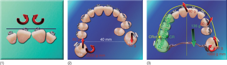
Fig. 7.8 (1) No anchorage is needed for correction of the depicted malocclusion, as the two units are displaced symmetrically against each other. (2) A slightly more complicated example of tooth movement where no anchorage problems exist. The patient requires distal rotation and mesialization of 17 and distal rotation and distalization of 27. This can be done with a transpalatal arch inserted into the lingual sheath of 17 delivering the desirable distally directed force to 27 at the level of the centre of resistance in the horizontal plane of space. The force system will not deliver any undesirable forces and is thus in a balance. (3) Three force systems (in red) should be applied to three distinct active units. The reactive force to be applied to the reactive unit is represented in green. The reactive force would generate an undesirable movement of the reactive unit around the centre of rotation (CRot). In order to increase anchorage, the occlusal contacts should be enhanced using composite onlays. An alternative would be the use of skeletal anchorage.
Sequencing the Treatment into Phases
The separation of treatment into phases is often related to the sequence of archwires and thus more related to the force level and the properties of the wire than to the exact tooth movement to be performed in the individual steps. However, there may be other reasons for which it is necessary to perform the treatment in phases (Burstone and Marcotte 2000):
- Anchorage cannot be maintained if all needed force systems are applied simultaneously. For example, it is often necessary to maintain the occlusion while moving the anterior units. Levelling of the buccal segments should be postponed, if necessary (Fig. 7.9).
- Space has to be created before certain tooth movements can be performed (Case 1, see supporting companion website for this book: www.wiley.com/go/melsen).
- Biomechanically, it may be difficult to design an appliance needed for a specific tooth movement and the tooth movement has to be done in steps. The anatomy may simply not allow the optimal appliance to be inserted (Fig. 7.10). If the desired tooth movements are divided into two stages, the goal could be achieved with less difficulty.
Fig. 7.9 (1) Patient in whom two incisors were intruded to the level of the contralateral teeth before the remaining incisors were included in the appliance. (2) The buccal segments were maintained passive throughout the treatment. (3) After treatment.
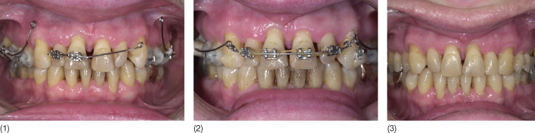
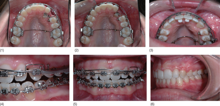
Fig. 7.10 (1) The palatally impacted canine was brought into the palate and freed from contact with the lateral incisor with a cantilever extending from the molar. (2) In the next phase, the canine was brought into the arch by using an overlay nickel titanium (Ni-Ti) arch. The bite opening necessary to allow the canine to be moved into the arch was obtained by using bonding pads on the lingual surface of the central incisors. (3–5) Buccal root torque with low-load deflection rate and a high moment-to-force ratio was obtained with a 0.17 × 0.25 inch titanium molybdenum (TMA) full arch extending from molar to molar and twisted 180° with respect to the canine bracket. Anchorage for the buccal root torque was obtained by using a stainless steel 0.17 × 0.25 inch wire bypassing the canine. Since a buccal root torque will implicitly deliver intrusion, this was prevented by the extruding round by-pass arch extending from central incisor to second premolar. (6) Post-treatment view.
Each phase of the treatment may require different mechanics. In one phase, there may be a single reactive unit and one or more active units. Only in cases with absolute consistency, when units are moved in the desired direction, will there be no reactive units. The following four aspects of treatment should be considered before establishing the sequence in which the tooth movements will be performed.
Anchorage
Phases in which little or no anchorage is needed should be first performed (Case 2, see www.wiley.com/go/melsen).
Generation of Space
Space conditions often determine the sequence of treatment. Since both sagittal and vertical movements require space, transverse corrections should generally be performed at the beginning of treatment. In the patient in Case 3 (see www.wiley.com/go/melsen, widening of the intercanine distance by intrusion of the upper canines was a pre-condition for the widening of the collapsed lower arch. Uprighting of the lingually tilted canines was the pre-condition for levelling and proclination of the incisors, which itself was a pre-condition for the correction of the lingually impacted lower premolar. Following the creation of the necessary space, vertical corrections should follow, as overjet cannot be corrected until the overbite has been reduced. Correction of the vertical and sagittal positions of the central incisors in this patient was combined by their simultaneous intrusion and retraction (Case 4, see www.wiley.com/go/melsen).
Mandibular Position
The mandibular position should be given special attention. A forced bite may generate temporomandibular disorder (TMD) and occlusal disturbances, which influences the mandibular position. This may result in anterior and posterior crossbites or scissors bite, which should be corrected early in treatment. Maintenance of the mandible in centric relation is especially important in TMD patients.
If in doubt, advantages and disadvantages related to different sequences should be evaluated before deciding the final sequence of the different phases. The correct sequencing of tooth movements is the principle underlying treatment with Invisalign®.
Appliance Selection and Design
Removable Appliances
In adult patients, appliances aim to deliver tooth movements and if relevant modelling of the alveolar process. Both removable and fixed appliances have their advantage and disadvantages.
Removable appliances comprise an acrylic plate with active units, including expansion screws and finger springs. A different approach to removable appliances is a series of thermoplastic splints developed to achieve pre-determined sequential tooth movements. Conventional plates can only be used for uncontrolled tipping, as the forces are transferred through a one-point contact, and thus are rarely used in adult patients. Thermoplastic splints can be used for more controlled tooth movements and are aimed primarily for use in the adult patient (Bollen et al. 2003; Clements et al. 2003). The series of splints know as Invisalign® is described in detail in Chapter 17.
Fixed Appliances
When using fixed appliances, the forces are transferred to the teeth via brackets. From a biomechanical point of view, it is important to distinguish between brackets that allow three-dimensional control and attachments that only have one point (single brackets, buttons, cleats, and hooks). Fixed appliances can be bonded both buccally and lingually, and the bracket design has a significant impact on the appliance, selection of archwires and auxiliaries used.
Bracket Selection
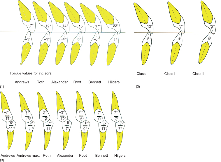
Brackets vary with respect to both material and design. Contemporary brackets have built-in first, second and third order control, following the principles of the pre-adjusted appliances introduced by Andrews (1976a,b). While the slot dimensions generally have been limited to 0.022 × 0.028 inch and 0.018 × 0.025 inch, the prescription of the built-in features varies considerably, according to what is considered the ideal (Planché 1997) (Fig. 7.11).
Fig. 7.11 (1) Comparison of the recommended bracket prescriptions regarding torque according to different authors. (2) Different torque values recommended for different malocclusions. (3) Different built-in angulation (second order) recommended by different authors.
(From Planché (1997) with permission from EDP Sciences. http://odf.edpsciences.org/.)
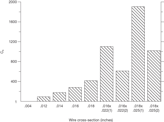
The dimensions of the archwire significantly influence the force levels delivered to the teeth. The rationale behind the reduction of the slot size from the original 0.022 inch to 0.018 inch was that three-dimensional control could be achieved with a wire of a smaller dimension (Fig. 7.12). These alterations were done when the available alloys were limited to steel and chrome cobalt alloys. With the introduction of high-tech memory alloys, the lower force level was no longer merely dependent on the dimensions of the wire but a larger slot dimension allows for a more rigid wire to be used in the reactive units.
Fig. 7.12 Relationship between wire dimension and stiffness (relative force level).
(Redrawn from Burstone (1982) Reproduced with permission from Elsevier.)
In relation to friction produced in sliding mechanics, not only is the dimension and the material of the brackets of importance but also the method of ligation (Nicolls 1968; Farrant 1977; Frank and Nikolai 1980; Schumacher et al. 1990; Iwasaki et al 2003). Conventional polyurethane modules increase friction when compared with stainless steel ligatures. The aim of the first self-ligating bracket, the Russell attachment, was reduction in ligating time and improvement in operator efficiency (Stolzenberg 1935, 1946), but a side effect was less resistance to sliding. However, interest in this bracket was temporary. A newer and more successful attempt to avoid ligation was the Speed® bracket, in which ligation was replaced with a cap that was passive in relation to wires of small dimensions but which became an active spring in relation to rectangular archwires (Fig. 7.13) (Hanson 1980, 1986; Berger 1990, 1999; Berger and Byloff 2001; Hanson 2002). A similar principle is used in the In-Ovation® bracket (Fig. 7.13) (Voudouris 1997a,b). In other self-ligating systems the slot is turned into a tube with a passive lid, e.g. the Damon® bracket (Ormco/Sybron) (Damon 1998a,b) (Fig. 7.13) and the SmartClip™ System from Unitek (Fig. 7.13). Thus most manufacturers now produce self-ligating brackets of varying designs and the reduction in chairside assistance, thus improving operator efficiency, has been used in the marketing of all products (Hanson 1986, 2002; Berger 1990; Shivapuja and Berger 1994; Damon 1998b; Turnbull and Birnie 2007).
Fig. 7.13 Different self-ligating brackets: (1) Speed brackets; (2) the active clip; (3) In-Ovation brackets; (4) Damon® brackets; and the (5) SmartClip™ bracket.
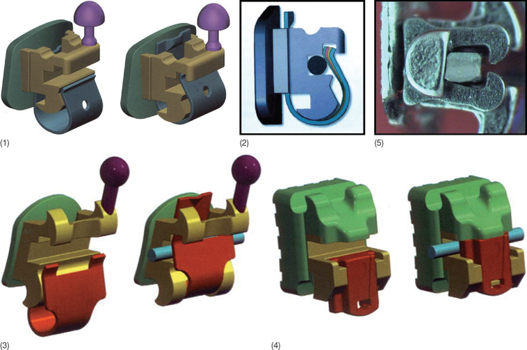
The focus has meanwhile been on additional advantages such as: improved control over tooth movements; constant low friction; less anchorage demanding; shorter treatment time; longer intervals between appointments; more comfortable for the patient; easier hygiene; reduced chair time; better work environment for the staff (Gottlieb et al. 1972; Hanson 1980; Shivapuja and Berger 1994; Voudouris 1997b; Pizzoni et al. 1998; Damon 1998b; Berger and Byloff 2001; Thorstenson and Kusy 2002a; Cacciafesta et al. 2003; Hain et al. 2003; Redlich et al. 2003; Thorstenson and Kusy 2003b; Henao and Kusy 2004, 2005; Kusy 2005). Most of these attributes are still controversial and to some degree related to the bracket design. The passive bracket has the advantage of maximum friction reduction initially (Damon 1998b; Harradine 2003), while brackets with an active clip may allow greater and more precise control of wire insertion (Fig. 7.13). The shorter gingival wall of the slot of inactive brackets such as Speed and In-Ovation may, on the other hand, reduce the length of the moment arm and consequently reduce the expression of torque (Harradine and Birnie 1996; Harradine 2001, 2003).
The modifications in bracket material and shape, which according to the manufacturers significantly facilitate sliding mechanics, are not supported by valid research. Several authors have claimed that low friction is a major factor in more efficient treatment (Shivapuja and Berger 1994; Harradine and Birnie 1996; Read-Ward et al. 1997; Hemingway et al. 2001; Cacciafesta et al. 2003; Hain et al. 2003; Harradine 2003; Katsaros and Dijkman 2003). On the one hand, as binding is more important than friction (Harradine 2001), the effect of archwire activation and bracket pre-angulation are sufficient to greatly reduce the disparity in friction levels between the conventional pre-adjusted and self-ligating brackets (Thorstenson and Kusy 2002a). Braun et al. (1999), on the other hand, demonstrated that resistance to sliding was reduced significantly when the dynamics of the oral environment were simulated.
Some authors claim that the use of self-ligating brackets reduces treatment time (Voudouris 1997a; Damon 1998a,b; Harradine 2001; Eberting et al. 2001). Damon found a reduction in the average treatment time in comparison with the traditional continuous steel archwire system but the reduced treatment time was not confirmed by Miles and colleagues (Miles et al. 2006; Miles 2007). Since none of the studies fulfil the requirements of a well-designed clinical trial, the comparison is not conclusive. It can only be inferred that self-ligating bracket systems demonstrate considerably lower static frictional resistance than a conventional steel-ligated bracket in the case of zero angulation. The reduction in friction characterizing self-ligating brackets is most pronounced when wires of smaller dimensions are used and is not advantageous during the final phase of treatment with full size archwires and reduced resistance to sliding results in reduced three-dimensional (3D) control (Thorstenson and Kusy 2002b). An example of an adult case treated with a self-ligating bracket system is shown in Case 5 (see www.wiley.com/go/melsen).
Sliding Mechanics
In relation to sliding mechanics teeth move along the archwire as beads along a string. Appliances with which tooth movement is instigated by means of loops or springs that are placed between the units do not necessitate displacement of the teeth with respect to the wire and resistance to sliding plays no role in these mechanics. These are discussed in later in this chapter.
Resistance to Sliding
The factors determining the resistance to the tooth movement along the archwire include classical or Coulomb friction, binding and notching. Friction is defined as the force that resists the relative motion or tendency to such motion of two bodies in contact (Kajdas 1990).
A distinction is also made between static frictional force, the smallest force required to start the motion, and kinetic frictional force, the force that resists sliding motion. Static friction is always higher than the kinetic force, which keeps the body in motion (Resnick and Halliday 1977). The former is considered of more importance in tooth movement, for when a tooth slides along an archwire, the movement occurs as a series of short jumps, and the resistance from static friction has to be overcome each time the tooth moves a little. Friction depends on the bracket and wire material, and the type of ligature delivering a normal force to the wire against the base of the slot.
As soon as the angle between the wire and the bracket slot exceeds the critical contact angle, the resistance to sliding will become dependent on the binding. Thorstenson and Kusy (2002a,b, 2003a,b) examined the effects of varying active tip (angulation) on the resistance to sliding and found that angulation beyond which the archwire first contacts the diagonally opposite corners of the bracket slot causes a similar rise in the resistance to sliding in self-ligated and conventional brackets (Kusy 2004). Although the critical binding angle is a product of the bracket size and the wire dimensions, the flexibility of the wire also plays a role. Stiffer wires result in higher resistance to sliding than flexible wires with the same dimensions.
Apart from the angle between the wire and the bracket, in other words, the type of the attempted tooth movement (Articolo and Kusy 1999; Thorstenson and Kusy 2002b, 2003a; Kusy 2004), notching may also influence the displacement of the bracket in relation to the wire. The occurrence of notching, which is the plastic deformation of the archwire, depends on the material of both the archwire and bracket and is related to the force system created between the archwire and the bracket. Notching is mostly seen on the lingual side of the archwire in the incisor and canine regions (Articolo et al. 2000).
Statically Determinate and Indeterminate Force Systems
A further approach to the classification of fixed appliances distinguishes between statically determinate and indeterminate systems. One-couple and two-couple mechanics is another way of denoting these systems (Davidovitch and Rebellato 1995; Isaacson and Rebellato 1995; Shroff et al. 1995).
In statically determinate systems acting between two units, the wire is only inserted into the bracket or the tube of one tooth and has a one-point contact with the other unit. Thus a force and a moment act on the first unit, and at the latter only a force. Figure 7.14 illustrates how the point of force application and the configuration of cantilevers can influence the force systems developed.
Fig. 7.14 (1) The point of force application determines the location of the line of action of the force. (2) The force will generally be perpendicular to the structural axis. (3) The configuration of a cantilever will, however, influence the direction of the force developed. A cantilever extending from a molar to an anterior tooth or block of teeth can thus develop an intrusive force that can also have a proclining or retracting component depending on the shape of the cantilever.
When a continuous arch is applied it is always a frictional and statically indeterminate system. Segmented appliances may apply to both statically determinate and indeterminate systems. Burstone and Koenig (1974) analysed the force systems developed in relation to a statically indeterminate system when a straight wire was inserted into brackets bonded to two teeth with different second-order angulations. Based on the ratio between the angles of the anterior and posterior brackets and the inter-bracket axis, they defined six basic two-unit geometries (Fig. />
Stay updated, free dental videos. Join our Telegram channel
VIDEdental - Online dental courses


