Chapter 5
ORTHODONTICS
5.1 Introduction to orthodontics
Orthodontics is the area of dentistry that concentrates on the correction of malocclusions. This includes correction of the way in which the teeth are aligned or the correction of the skeletal relationship between the upper and lower dental arches. The aim of orthodontics, therefore, is to achieve perfect occlusion.
Modern orthodontics is based in the main on the work of two people, Edward Angle, whose classification of malocclusion is universally used, and Lawrence Andrews, whose ‘six keys to occlusion’ re-defined Angle’s work.
Indications for orthodontic treatment
The use of removable orthodontic appliances has reduced somewhat in recent years due to the advances that have been made in fixed appliance therapy. However, there is a role for removable appliances as an adjunct to fixed appliance treatment and in specially selected patients in whom the limitations of the removable appliance are not exceeded. They are particularly effective in mixed dentition malocclusions, as space maintainers and for retainer appliances following treatment with fixed appliances.
Benefits of orthodontic treatment
1. Aesthetics
A person’s appearance is important to them, as is the need to conform to what is regarded as normal within their culture. A dental appearance that is outside of what is felt to be normal may lead to a feeling of low self-esteem. Treatment of a patient with a malocclusion that is causing them to experience low self-esteem will give greater confidence and a feeling of well-being about their dental appearance.
2. Function
A malocclusion may interfere with the correct function of speech. The most common problem is the pronunciation of the letter ‘S’.
3. Dental health
Overcrowding of the teeth may lead to caries due to the inability to keep the teeth clean in an effective way.
Disadvantages of orthodontic treatment
1. Root resorption
This can happen if the bone of the palatal vault does not respond to the movement of, for example, an incisor, and therefore acts to restrict its movement; this may then lead to resorption of the incisor apex instead of the bone.
2. Loss of periodontal support
If too great a force is applied to a tooth, the blood capillaries are occluded and cells in the periodontal ligament die. This area is then structureless or ‘hyalinised’ The hyaline material consists of compressed collagen.
3. Decalcification
When fixed appliances are removed, sometimes white spot lesions are noted in the enamel of the tooth underneath where the bracket was bonded; these are due to decalcification of the enamel.
4. Soft tissue damage
The soft tissues can be injured and painful and sore areas can occur under wires or the baseplate of an appliance. However, these problems are generally dealt with fairly easily.
5.2 Classification of malocclusions
Angle’s classification of malocclusion
Known as the ‘father of orthodontics’, the American orthodontist Edward Hartley Angle (1855–1930) produced a classification for the different forms of malocclusion.
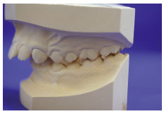
Class I
This is the normal anteroposterior relationship of the maxilla to the mandible (no skeletal discrepancy) (Figure 5.2.1). Characterised by the mesio-buccal cusp of the first upper permanent molar occluding in the mesio-buccal groove of the lower first permanent molar.

A Class I relationship is usually accepted as normal and although there are no skeletal discrepancies there may be some problems that can be corrected with removable appliances. The use of a removable appliance will depend on the problem and whether a removable appliance can deliver the kind of tooth movement that is required. Often simple tooth movements can be achieved easily with active components such as springs (sometimes along with necessary tooth extractions).
Class II
This is a posterior relationship of the mandible to the maxilla. The mesio-buccal cusp of the first upper permanent molar occludes mesial to the mesio-buccal groove of the lower first permanent molar.
Division 1: The maxillary incisors are proclined, giving rise to a ‘buck-toothed’ appearance (Figure 5.2.2).
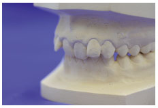
Division 2: The upper centrals are proclined and the upper laterals are retroclined; there is also a deep overbite associated with this division (Figure 5.2.3).
Where there is no skeletal discrepancy but the upper incisors are very proclined the use of a removable appliance can achieve very good results. However, where the overjet is because of a skeletal problem, functional appliance therapy is usually needed followed by a course of fixed appliance treatment.
Class III
This is an anterior relationship of the mandible to the maxilla. The mesio-buccal cusp of the upper first permanent molar occludes distal to the mesio-buccal groove of the lower first permanent molar (Figure 5.2.4).
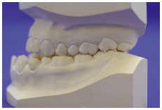
To correct a Class III malocclusion satisfactorily with removable appliances there should only be a mild Class III relationship or ideally a Class I skeletal relationship with the incisors being in a Class III relationship.
Andrew’s six keys to occlusion
Orthodontic treatment falls into one of two areas: ‘camouflage’ and ‘modification’. Treatment goals have to be decided on early and may possibly be a compromise between the patient’s most favoured outcome which might purely be one of aesthetics where as an orthodontist may wish to achieve perfect occlusion.
Designing orthodontic appliances is a team exercise involving the orthodontist and technician. In order to do so, the technician should understand the concepts of anchorage, retention and tooth movement.
5.3 Theory of tooth movement
When force is applied to the crown of a tooth it will move slightly within the surrounding periodontal ligament. Then, because of the areas of compression that have been set up, the tooth will move to a new position in the mouth if the force is applied over a sufficient length of time. There are three kinds of movement that one can expect: tipping, bodily movement and rotation about the long axis. Tipping of a tooth is the only kind of movement that a removable appliance can achieve, bodily moving a tooth is only possible with fixed appliances and rotations can be achieved with removable appliances if managed closely.
Removable appliances
A removable appliance is one that can be easily removed from the mouth, however, this does not mean that they are for part-time wear.
The use of removable orthodontic appliances has fallen due to the limited range of movements that can be achieved with them and consequently the popularity offixed appliance therapies. But they are still required in the form of retainers and functional appliances used in combination with fixed appliance therapy. In addition, they can be used for simple movements such as tipping a tooth, which are easily achieved with them.
Anchorage
Anchorage is an important consideration when moving teeth and should not be confused with retention (how an appliance is held in the mouth). Anchorage is the resistance to movement by the teeth when an orthodontic force is applied.
Incorrect provision of anchorage for an appliance will allow the tooth that is being moved to stay where it is, and the ‘anchoring’ teeth to move.
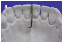
Removable appliances often rely on intra-maxillary traction, where anchorage is obtained from within the same arch. Reciprocal anchorage is also possible, i.e. the force of movement of two teeth, or groups of teeth, cancels each other out. A simple example is that of closing a diastema. Other than in these cases, the reactionary force generated to move a tooth is distributed to other teeth such that they can resist movement.
Retention
The term retention is used in orthodontics to mean two things:
A removable appliance is held in the mouth in two ways. Firstly, by using clasps in tooth undercuts and, secondly, by means of the baseplate which may also use undercut areas on the palatal aspect of the teeth and in the same way as a denture, use the close fit of the plate and saliva on the palate to create cohesion between the appliance.
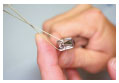
Maintaining teeth in their new position is carried out using retainers. Either Hawley or Essix-type retainers can be used and do the job equally well. Essix-type retainers are worn for much less time, generally at night; and as they are virtually invisible when in place they are becoming increasingly popular.
5.4 Basic wire bending techniques
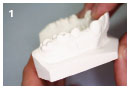
Casting working model
Component construction
Removable appliance construction
Introduction
A number of basic bends are used in the construction of orthodontic appliances.
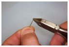
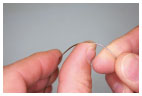
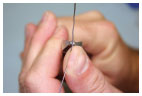
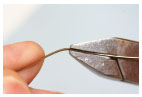
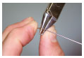
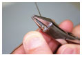
Using pliers
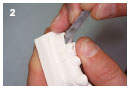
The pliers should only be used as a vice to grip the wire; nearly all wire bending is done with the thumb and index finger.
- Adams pliers
- Spring-forming pliers
- Wire cutters
- 0.7 mm stainless steel wire
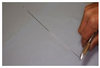
Straightening wire
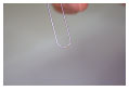
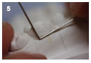
Most wire is supplied on reels, therefore once a length of wire has been cut, it will have a pronounced curve. In most cases the wire will require straightening before a component can be made.

Soft curves
When forming soft curves the wire does not require straightening; the curve that is already present can be exaggerated to help form the curve. This is done for components such as the labial bow.
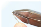
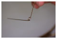
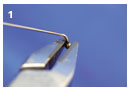
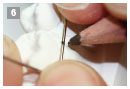
Right angle bends
Acute angled bends
These types of bend are demanding on your fingers and require a firm grip on the pliers.
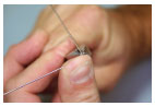
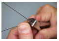
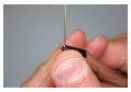
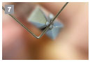
Coils and loops
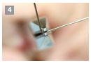
To make coils and loops, found in springs and labial bows, ‘spring-forming’ pliers must be used. Making uniform coils and loops take practice but are simple once the technique has been mastered. The wire should be bent around the conical beak of the spring-forming pliers and constantly moved so that the square beak does not hinder the process.
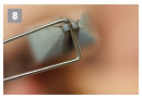
Large radius bends
5.5 Making passive components
Passive components are the parts of a removable appliance that are responsible for holding the appliance in the mouth and holding the teeth that are not being moved.
5.6 Producing ball-ended clasps
Casting working model
Component construction
Removable appliance construction
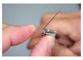
Introduction
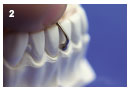
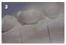
Ball-ended clasps are quick and easy to make. They are bought pre-formed so just need fitting to the model. The ball end fits low down in between two teeth and rests on the gingival margin.
- Adams pliers
- Wire cutters
- Pre-formed ball-ended clasps, either 0.8 or 0.9 mm
- 2B pencil
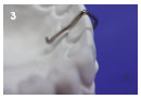
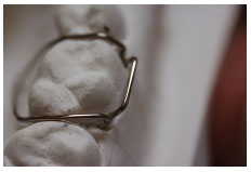
5.7 The Adams clasp
Adams clasps are the most widely used clasp on removable appliances, particularly on molars and premolars (Figure 5.7.1). There are other clasps that can and sometimes are used but the Adams is the most versatile.
- Adams pliers
- Wire cutters
- 0.7 mm stainless steel wire
- 2B pencil
- Ash No. 10 carver

Stay updated, free dental videos. Join our Telegram channel
VIDEdental - Online dental courses


