Chapter 5
Cone-beam computed tomography
What Is Cone-Beam Computed Tomography?
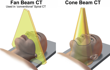
Cone-beam computed tomography (CBCT) uses a cone-shaped beam of X-ray photons rather than the fan-shaped beam used by helical CT (HCT) (Figure 5.1). The cone’s shape can be either round or rectangular. CBCT can scan the region of interest in up to a single 360° rotation in contrast to the multiple rotations required by HCT using a fan beam. CBCT interrogates a much smaller volume of tissue than HCT. CBCT is also frequently called dental computed tomography (DCT) or cone-beam volumetric tomography (CBVT) or volumetric computed tomography (VCT). Farman prefers CBCT because this describes the principles of operation rather than its application in dentistry or the resulting dataset.”1 CBCT has been applied to respiratory,2 breast,3 and cardiac imaging.4 CBCT has also been used during craniospinal surgery.5
Figure 5.1. The fan beam upon which helical computed tomography is based interrogates only a slice of tissue, whereas the cone beam of cone-beam computed tomography interrogates a 3-dimensional region within a 360° rotation.
Reprinted with permission from MacDonald-Jankowski DS, Orpe E. Computed tomography for oral and maxillofacial surgeons. Part 2: Cone-beam computed tomography. Asian Journal of Oral Maxillofacial Surgery 2006;18:85–92.

Why Is Cone-Beam Computed Tomography Desirable?
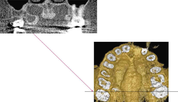
The advantage of CBCT is its superior spatial resolution (the ability to identify separately 2 minute points very close together), relative to HCT, of structures with high-contrast mineralized tissue such as teeth and bone. CBCT, in addition to producing 3-D images, can produce 2-D images similar to the panoramic and cross-sectional reconstructions produced for preimplant assessment. Figure 5.2 displays both the 2-D and 3-D reconstructions of a torus palatinus and exostoses.
Figure 5.2. Display of the coronal (top); and 3-dimensional (bottom) reconstruction of a torus palatinus and bilateral exotoses on the palatal aspect of the maxillary tuberosities. The metallic artifact observed on the coronal reconstruction at the level of the black line on the bottom-right figure was minimized in the 3-dimensional reconstruction by excluding most of the crowns, hence the pulp chambers rather then occlusal surfaces. There is still some residual metallic artifact observed as white streaks on both exostoses. The unit used was an iCAT with a 0.2 mm voxel size.
Reprinted with permission from MacDonald-Jankowski DS, Orpe E. Computed tomography for oral and maxillofacial surgeons. Part 2: Cone-beam computed tomography. Asian Journal of Oral Maxillofacial Surgery 2006;18:85–92.

Although HCT is an improvement on conventional radiography with regard to elimination superimposition, 3-D reconstruction, and its excellent contrast resolution, its spatial resolution is still inadequate, particularly in comparison to intraoral radiography. The current best spatial resolution for CBCT is 6.5 line pairs per mm (0.076 mm minimum voxel size), whereas for intraoral conventional radiography it is at least 2 times that (see Table 2.1). Therefore, intraoral images will continue to display fine features such as the ground-glass and peau d’orange (orange peel) appearance of bone, the poorer-defined margins associated with fibrous dysplasia, and the fine cortices of other lesions. On the other hand, the CBCT’s panoramic reconstruction is superior to that of a conventional panoramic X-ray because it displays no superimposed secondary images and is geometrically more accurate.
How Does Cone-Beam Computed Tomography Differ from Helical Computed Tomography?
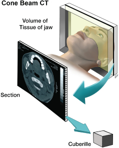
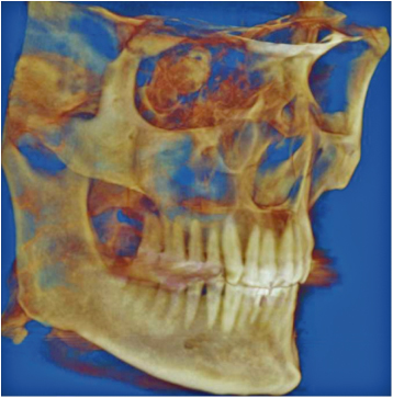
HCT uses a planar geometry and 2-D reconstruction, whereas CBCT performs nonplanar geometry and a 3-D reconstruction.6 CBCT reconstructs the 3-D images by generating cuberilles directly, each with its own attenuation coefficient (Figure 5.3; compare to Figure 4.6). This allows 3-D reconstructions with better spatial resolution in the Z plane (patient’s long axis), in addition to the axial (XY) plane. Except perhaps for the most modern Multidetector computed tomographic (MDCT) units, HCT can only produce cuberilles secondarily from voxels (see Figure 4.6). CBCT’s cuberilles are called isotropic voxels, which result in highly detailed 3-D images (Figure 5.4).
Figure 5.3. Cone-beam computed tomography reconstructs the 3-dimensional images by generating cuberilles directly, each with its own attenuation coefficient. This allows 3-dimensional reconstructions with better resolution in the Z axis, in addition to the axial (XY) plane. Helical computed tomography, except the most modern MDCT, can only produce cuberilles secondarily from voxels (see Figure 4.6).
Reprinted with permission from MacDonald-Jankowski DS, Orpe E. Computed tomography for oral and maxillofacial surgeons. Part 2: Cone-beam computed tomography. Asian Journal of Oral Maxillofacial Surgery 2006;18:85–92.

Figure 5.4. Three-dimensional (3-D) reconstruction of the data captured by a cone-beam computed tomographic (CBCT) unit (iCAT). Because this image is constructed of isotropic cuberilles, the spatial resolution is very good in all three dimensions. Figure courtesy of Dr. Babak Chehroudi, Faculty of Dentistry, University of British Columbia.

Although many reconstruction algorithms for CBCT have not achieved the performance observed for the best MDCT, this is an area of active research that will continue to improve the quality of CBCT technology, with particular regard to its software.7 Vannier described “craniofacial” CBCT as a “disruptive technology” that changed the entire course of an industry.8 Because CBCT is relatively cheap and compact, it can be readily accommodated in the practitioner’s office where space and operating costs are a small fraction of those incurred by HCT.8 Unfortunately, this ease of access facilitates other significant problems, particularly inappropriate criteria for its use. This is discussed later in this chapter.
Most CBCT makes now use flat panel detectors (FPDs) constructed of amorphous silicon, rather than the image intensifiers frequently used in HCT. Some CBCTs also use solid state chips.1 FPDs have the advantage of not producing the geometric distortion that occurs with image intensifiers. In addition, FPDs have a wider dynamic range, better signal to noise ratio (SNR), and better spatial resolution.9
Patient Posture During a Cone-Beam Computed Tomography Examination
With the exception of the NewTom 3G, which exposes the patient in the supine position, almost all CBCT units expose the patient seated or standing upright (Figure 5.5). The gantry used can range from the one designed solely for the CBCT unit, such as the iCAT in Figure 5.5a, to that used by the Promax 3D which is the same as that used for panoramic tomography and cephalometry (Figure 5.5b.).
Figure 5.5. There are many types of cone-beam computed tomographic units currently available. Two examples are displayed. The robust iCAT (a) has a seat, whereas the Promax 3D (b) uses a panoramic radiographic gantry in which the patient stands. The control for positioning the patient within the Promax 3D is shown in (c). The exposure of all units should be directed from outside the room in which the CBCT unit is sited. Such a con/>
Stay updated, free dental videos. Join our Telegram channel

VIDEdental - Online dental courses


