Part 2: Advanced imaging modalities
Chapter 4
Helical computed tomography
Introduction
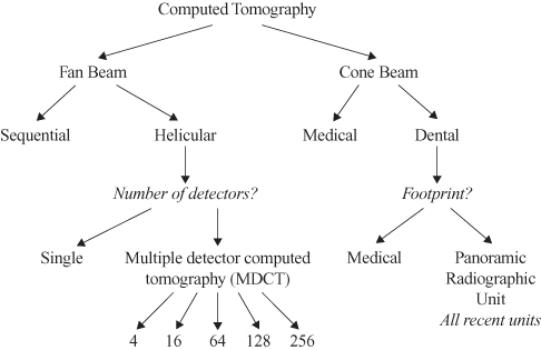
Computed tomography (CT) can be divided broadly into fan-beam CT (including helical computed tomography [HCT] and its subsets), and cone-beam computed tomography (CBCT) (Figure 4.1); the latter is addressed in Chapter 5.
Figure 4.1. The classification and nomenclature of computed tomography.
Computed tomography, particularly HCT, is increasingly available for the investigation of face and jaw lesions. This chapter introduces the various types of computed tomography, while concentrating on HCT, and covers window level and width, pitch, multidetector computed tomography, 3-dimensional (3-D) reformatting, and the limitations of HCT. The indications for an increased need for HCT are discussed.
Why Do We Need Computed Tomography?
Formerly, clinicians relied on a clinical examination and “conventional radiography” (traditional 2-dimensional imaging) to assess and diagnose lesions affecting the jawbones. Unfortunately, conventional radiography generally reveals images that lack the sensitivity to display small changes in the bone. Conventional radiography also presents only as a 2-dimensional (2-D) image the superimposition of all structures within the 3-D volume of the region examined.
What Are the Basic Construction and Principles of Computed Tomography?
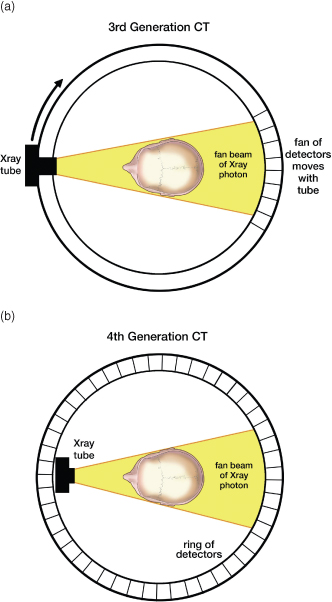
The CT unit has 3 main components, as shown in Figure 4.2. The CT unit itself consists of the gantry (some of which may be angled up to 30°) and the patient table (or bed or couch) that moves the patient through the aperture in the gantry (Figure 4.2a), and the control console (Figure 4.2b). There are currently 2 types of CT unit available: the third- and fourth-generation units (Figure 4.3). The former constitutes the vast majority of CT equipment. For the third-generation CT, the X-ray tube and the detectors, which occupy an arc, are fixed in opposing positions within the gantry and rotate as a unit around the patient when in operation (Figure 4.3a), whereas for the fourth-generation unit, the X-ray tube alone rotates within a complete stationary ring of detectors (Figure 4.3b). The advantage of the fourth-generation unit is that the detectors have time to recover before being irradiated again.
Figure 4.2. The 3 components of the computed tomography unit. (a) The gantry, containing the X-ray tube and detectors, and the table upon which the patient lies and is progressively advanced through the gantry; and (b) the control console with monitor. This is separated from the CT unit by a lead wall, including a lead glass window. It is crucial to observe the patient and gantry throughout the entire exposure, in case the exposure needs to be terminated.
Reprinted with permission from MacDonald-Jankowski DS, Li TK. Computed tomography for oral and maxillofacial surgeons. Part 1: Spiral computed tomography. Asian Journal of Oral Maxillofacial Surgery 2006;18:68–77.
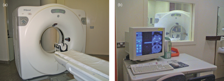
Figure 4.3. The 2 types of computed tomography units currently available. (a) The third-generation computed tomography unit permits a fan array of detectors to rotate around the patient in tandem with the rotating X-ray tube—the X-ray beam is fan-shaped; and (b) the fourth-generation computed tomography unit only permits rotation of the X-ray tube within the continuous, but stationary, array of detectors—the X-ray beam is fan-shaped.
Reprinted with permission from MacDonald-Jankowski DS, Li TK. Computed tomography for oral and maxillofacial surgeons. Part 1: Spiral computed tomography. Asian Journal of Oral Maxillofacial Surgery 2006;18:68–77.
How is the Computed Tomographic Image Displayed?
The display is a digital image reconstructed by the computer as pixels (picture elements), which represent a 3-D block of tissue. The voxel is the pixel size multiplied by the slice thickness (the voxel’s length is from as low as 1 mm in some units to 20 mm). Each pixel is assigned a CT number (see later) representing tissue density. This density is proportional to the degree to which the material within the voxel has attenuated the X-ray beam. The resultant attenuation coefficient of a particular voxel reflects the mean of all tissues within it, the proportion of hard to soft tissues, and the voxel length (slice thickness).
There are 3 planes: X, Y, and Z. X and Y together represent the axial plane, a transverse plane through the patient. The Z plane represents the head-to-toe long axis of the patient. Upon inspection of an axial section, the pixels are represented by 2-D squares in the axial (XY) plane of a 3-D section of tissue of a thickness in the Z plane.
What is Helical Computed Tomography?
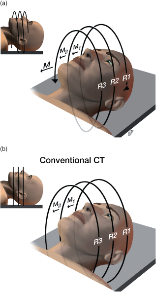
HCT is also known as volume acquisition CT. As Hounsfield’s genius introduced and developed the concept of CT in 1968, that of Kalender introduced HCT. HCT violates a previous firm tenet of radiology: the patient should not move during the exposure. Instead, HCT requires that the patient, who remains motionless, be moved through the aperture of the gantry during the generation of X-rays by the rotating X-ray head (Figure 4.4a), creating a helix or spiral of data. This is in contrast to the separate incremental slices, which are stacked like coins, of the conventional sequential slice CT (the original technology of the 1970s and l980s), now frequently called “sequential CT” (SeqCT) (Figure 4.4b).
Figure 4.4. Helical and sequential computed tomography. (a) In helical computed tomography, the rotating X-ray tube describes a helix or spiral as it exposes the patient on the bed continuously moving through the gantry; and (b) in sequential computed tomography, the rotating X-ray tube can only describe complete loops between incremental movements of the patient’s table through the gantry.
Reprinted with permission from MacDonald-Jankowski DS, Li TK. Computed tomography for oral and maxillofacial surgeons. Part 1: Spiral computed tomography. Asian Journal of Oral Maxillofacial Surgery 2006;18:68–77.
How is Helical Computed Tomography Better Than Sequential Computed Tomography?
Because there is a continuous string of data encompassing a volume of the patient with HCT, this data can be readily reconstructed to give 3-D images. To achieve the same for SeqCT, the patient would need to undergo a second exposure overlapping with the first exposure, thus doubling the radiation dose. Because the data produced by HCT represents a continuous volume of the patient, it can be readily reconfigured to produce slices in any plane, including the coronal plane. However, the generation of coronal sections by SeqCT would require a reexposure of the patient through a coronal head position.
What Does the Data Found on the Image Represent?
Reviewers of HCT images should understand these terms: bone and soft-tissue windows, window width (WW) and level (WE), and pitch.
BONE AND SOFT-TISSUE WINDOWS
Bone and soft-tissue windows and their widths and levels are expressed in Hounsfield units (HU), which are also called “CT numbers.” These range from a minimum of −1000 HU representing air (fixed point), through 0 HU representing water (fixed point), up to 3000 HU representing dense metal or bone. Bone and soft-tissue windows (Figure 4.5) are 2 of the 3 standard protocols for viewing the data captured by CT; the air window is the third protocol and is used mainly by respiratory physicians. Each of these protocols optimizes viewing of tissue types by appropriately adjusting the WL and WW. The soft-tissue window for face and jaw lesions is sited close to that of water (0 HU), WL at 40 to 60 HU, and WW at 250 HU, whereas the bone windows for such lesions are WL at 250 to 500 HU and WW 1000 to 2000 HU or greater. The level may be defined as equivalent to tuning a radio into the desired frequency, whereas the width is equivalent to a filter. Formerly, the latter varied greatly depending upon ind/>
Stay updated, free dental videos. Join our Telegram channel
VIDEdental - Online dental courses


