Digital Imaging
John B. Ludlow and André Mol
The advent of digital imaging has revolutionized radiology. This revolution is the result of both technologic innovation in image acquisition processes and the development of networked computing systems for image retrieval and transmission. Dentistry is seeing a steady increase in the use of these technologies, improvement of software interfaces, and introduction of new products. Numerous forces are driving the shift from film to digital systems. The detrimental effects of inadequate film processing on diagnostic quality and the difficulty of maintaining high-quality chemical processing are well documented. Digital imaging eliminates chemical processing. Hazardous wastes in the form of processing chemicals and lead foil are eliminated with digital systems. Images can be electronically transferred to other health care providers without any alteration of the original image quality. In addition, digital intraoral receptors require less radiation than film, thus reducing patient exposure. Finally, digital imaging allows enhancements, measurements, and corrections not available with film.
Digital systems also have many disadvantages compared with film. The initial expense of setting up a digital imaging system is relatively high. Certain components, such as the electronic x-ray receptor used in some intraoral systems, are susceptible to rough handling and are costly to replace. Because digital systems use evolving technologies, there is a risk—perhaps even a likelihood—of systems becoming obsolete or manufacturers going out of business. The excellent image quality and comparatively low cost of a properly exposed and processed film keeps film-based radiography competitive with digital alternatives.
The trends are certain, however; computers play a role in most dental practices, and that role is expanding as various functions, including appointment scheduling, procedure billing, and patient charting, are integrated into seamless practice management software solutions. It is no longer a matter of if but rather when most dental practices will use digital imaging. Already during this time of transition, film-based practices are confronted with digital images from practices that have implemented digital radiography. This chapter describes the characteristics of digital images, image receptors, display options, and storage devices and discusses digital image processing.
Analog Versus Digital
The term digital in digital imaging refers to the numeric format of the image content and its discreteness. Conventional film images can be considered an analog medium, in which differences in the size and distribution of black metallic silver result in a continuous density spectrum. Digital images are numeric and discrete in two ways: (1) in terms of the spatial distribution of the picture elements (pixels) and (2) in terms of the different shades of gray of each of the pixels. A digital image consists of a large collection of individual pixels organized in a matrix of rows and columns (Fig. 4-1). Each pixel has a row and column coordinate that uniquely identifies its location in the matrix. The formation of a digital image requires several steps, beginning with analog processes. At each pixel of an electronic detector, the absorption of x rays generates a small voltage. More x rays generate a higher voltage and vice versa. At each pixel, the voltage can fluctuate between a minimum and maximum value and is therefore an analog signal (Fig. 4-2, A).
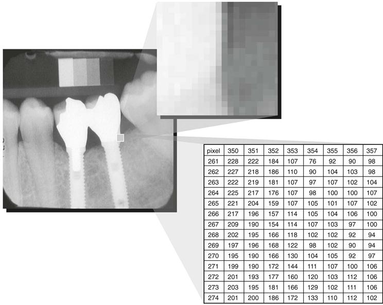
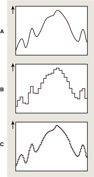
Production of a digital image requires a process called analog-to-digital conversion (ADC). ADC consists of two steps: (1) sampling and (2) quantization. Sampling means that a small range of voltage values are grouped together as a single value (Fig. 4-2, B). Narrow sampling better mimics the original signal but leads to larger memory requirements for the resulting digital image (Fig. 4-2, C). Once sampled, the signal is quantized, which means that every sampled signal is assigned a value. These values are stored in the computer and represent the image. For the clinician to see the image, the computer organizes the pixels in their proper locations and displays a shade of gray that corresponds to the number that was assigned during the quantization step.
To understand the strengths and weaknesses of digital radiography, the clinician establishes which elements of the radiographic imaging chain stay the same and which ones change. The imaging chain can be conceptualized as a series of interconnecting links beginning with the generation of x rays. Exposure factors, patient factors, and the projection geometry determine how the x-ray beam is attenuated. A portion of the unattenuated x-ray beam is captured by the image receptor to form a latent image. This latent image is processed and converted into a real image, which is viewed and interpreted by the clinician. The use of digital detectors changes the way we acquire, store, retrieve, and display images. However, besides an adjustment of the exposure time, digital detectors do not fundamentally change the way in which x rays are selectively attenuated by the tissues of the patient. The physics of the interaction of x rays with matter and the effects of the projection geometry on the appearance of the radiographic image are unaltered and remain critically important for understanding image content and for optimizing image quality.
Digital Image Receptors
Digital image receptors encompass numerous different technologies and come in many different sizes and shapes. Numerous different and sometimes confusing names are in use to identify these receptors in medicine and dentistry. The most useful distinction is that between two main technologies: (1) solid-state technology and (2) photostimulable phosphor (PSP) technology. Although solid-state detectors can be subdivided further, these detectors have in common certain physical properties and the ability to generate a digital image in the computer without any other external device. In medicine, the use of solid-state detectors is referred to as digital radiography. In dentistry, intraoral solid-state detectors are often called sensors. The other main technology, PSP, consists of a phosphor-coated plate in which a latent image is formed after x-ray exposure. The latent image is converted to a digital image by a scanning device through stimulation by laser light. This technology is sometimes referred to as storage phosphor on the basis of the notion that the image information is temporarily stored within the phosphor. Other times the term image plates is used to differentiate them from film and solid-state detectors. The use of PSP plates in medical radiology is referred to as computed radiography.
Solid-State Detectors
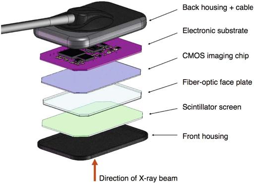
Solid-state detectors collect the charge generated by x rays in a solid semiconducting material (Fig. 4-3). The key clinical feature of these detectors is the rapid availability of the image after exposure. The matrix and its associated readout and amplifying electronics of intraoral detectors are enclosed within a plastic housing to protect them from the oral environment. These elements of the detector consume part of the real estate of the sensor so that the active area of the sensor is smaller than its total surface area. Sensor bulk, although reduced by continued miniaturization of the electronic components, is a potential drawback of intraoral solid-state detectors. In addition, most detectors incorporate an electronic cable to transfer data to the computer. The presence of a cable can make positioning of the sensor more challenging and requires some adaptation. It also results in increased vulnerability of the device. Manufacturers have addressed these issues in various ways. Some manufacturers have changed the location of the cable attachment to the corner of the sensor. Others offer sensors with magnetic connectors, induction connectors, or reinforced cables to reduce accidental damage to the device. Wireless radiofrequency transmission also has been introduced to eliminate the cable altogether. Wireless radiofrequency transmission frees the detector from a direct tether to the computer, but it necessitates some additional electronic components, thus increasing the overall bulk of the sensor.
Many manufacturers produce detectors with varying active sensor areas roughly corresponding to the different sizes of intraoral film. Detectors without flaws are relatively expensive to produce, and the expense of the detector increases with increasing matrix size (total number of pixels). Pixel size ranges from less than 20 to 70 micrometers (µm). Three types of solid-state sensors are in common use.
Charge-Coupled Device
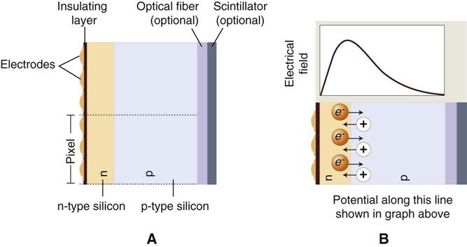
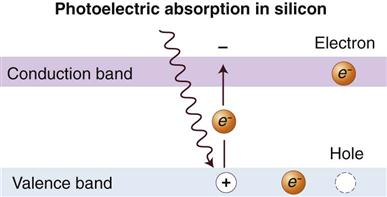
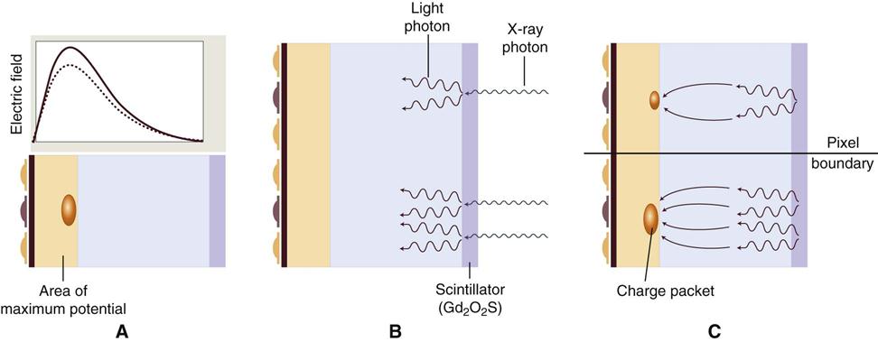
The charge-coupled device (CCD), introduced to dentistry in 1987, was the first digital image receptor to be adapted for intraoral imaging. The CCD uses a thin wafer of silicon as the basis for image recording. The silicon crystals are formed in a pixel matrix (Fig. 4-4). When exposed to radiation, the covalent bonds between silicon atoms are broken, producing electron-hole pairs (Fig. 4-5). The number of electron-hole pairs that are formed is proportional to the amount of exposure that an area receives. The electrons are attracted toward the most positive potential in the device, where they create “charge packets.” Each packet corresponds to one pixel. The charge pattern formed from the individual pixels in the matrix represents the latent image (Fig. 4-6). The image is read by transferring each row of pixel charges from one pixel to the next in a “bucket brigade” fashion. As a charge reaches the end of its row, it is transferred to a readout amplifier and transmitted as a voltage to the analog-to-digital converter located within or connected to the computer. Voltages from each pixel are sampled and assigned a numeric value representing a gray level (ADC). Because CCD detectors are more sensitive to light than to x rays, most manufacturers use a layer of scintillating material coated directly on the CCD surface or coupled to the surface by fiberoptics. This scintillating material increases the x-ray absorption efficiency of the detector. Gadolinium oxybromide compounds similar to those used in rare earth radiographic screens or cesium iodide are examples of scintillators that have been used for this purpose.
CCDs have also been made in linear arrays of a few pixels wide and many pixels long for panoramic and cephalometric imaging. In the case of panoramic units, the CCD is fixed in position opposite to the x-ray source with the long axis of the array oriented parallel to the fan-shaped x-ray beam. Some manufacturers provide CCD sensors that may be retrofitted to older panoramic units. In contrast to film imaging, the mechanics for cephalometric imaging are different. Construction of a single CCD of a size that could simultaneously capture the area of a full skull would be prohibitively expensive. Combining a linear CCD array and a slit-shaped x-ray beam with a scanning motion permits scanning of the skull over several seconds. One disadvantage of this approach is the increased possibility of patient movement artifacts during the several seconds required to complete a scan.
Complementary Metal Oxide Semiconductors
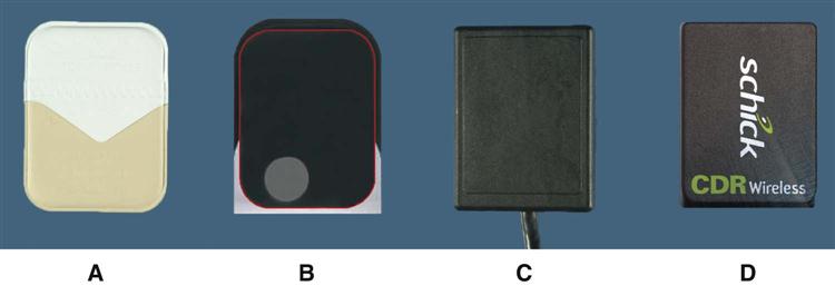
Complementary metal oxide semiconductor (CMOS) technology is the basis for typical consumer-grade digital cameras. These detectors are also silicon-based semiconductors but are fundamentally different from CCDs in the way that pixel charges are read. Each pixel is isolated from its neighboring pixels and is directly connected to a transistor. Similar to the CCD, electron-hole pairs are generated within the pixel in proportion to the amount of x-ray energy that is absorbed. This charge is transferred to the transistor as a small voltage. The voltage in each transistor can be addressed separately, read by a frame grabber, and stored and displayed as a digital gray value. CMOS technology is widely used in the construction of computer central processing unit chips and digital camera detectors, and the technology is less expensive than that used in the manufacturing of CCDs. Several manufacturers are using this technology for intraoral imaging applications (Fig. 4-7).
Flat Panel Detectors
Flat panel detectors are used for medical imaging but have also been used in several extraoral imaging devices. The detectors can provide relatively large matrix areas with pixel sizes less than 100 µm; this allows direct digital imaging of larger areas of the body, including the head. Two approaches have been taken in selecting x-ray–sensitive materials for flat panel detectors. Indirect detectors are sensitive to visible light, and an intensifying screen (gadolinium oxysulfide or cesium iodide) is used to convert x-ray energy into light. The performance of these devices is determined by the thickness of the intensifying screen. Thicker screens are more efficient but allow greater diffusion of light photons, leading to image unsharpness. Direct detectors use a photoconductor material (selenium) with properties similar to silicon and a higher atomic number, which permits more efficient absorption of x rays. Under the influence of an applied electrical field, the electrons that are freed during x-ray exposure of the selenium are conducted in a direct line to an underlying thin film transistor (TFT) detector element. Direct detectors using selenium (Z = 34) provide higher resolution but lower efficiency compared with indirect detectors using intensifying screens with gadolinium (Z = 64) or cesium (Z = 55). The electrical energy generated is proportional to the x-ray exposure and is stored at each pixel in a capacitor. The energy is released and read out by applying appropriate row and column voltages to a particular pixel’s transistor. Flat panel detectors are expensive and likely to be limited to specialized imaging tasks, such as cone-beam computed tomography (CT).
Photostimulable Phosphor
PSP plates absorb and store energy from x rays and release this energy as light (phosphorescence) when stimulated by another light of an appropriate wavelength. To the extent that the stimulating light and phosphorescent light wavelengths differ, the two may be distinguished, and the phosphorescence can be quantified as a measure of the amount of x-ray energy that the material has absorbed.
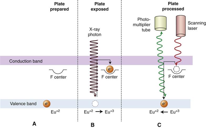
The PSP material used for radiographic imaging is “europium-doped” barium fluorohalide. Barium in combination with iodine, chlorine, or bromine forms a crystal lattice. The addition of europium (Eu+2) creates imperfections in this lattice. When exposed to a sufficiently energetic source of radiation, valence electrons in europium can absorb energy and move into the conduction band. These electrons migrate to nearby halogen vacancies (F-centers) in the fluorohalide lattice and may become trapped there in a metastable state. While in this state, the number of trapped electrons is proportional to x-ray exposure and represents a latent image. When stimulated by red light of around 600 nm, the barium fluorohalide releases trapped electrons to the conduction band. When an electron returns to the Eu+3 ion, energy is released in the green spectrum between 300 and 500 nm (Fig. 4-8). Fiberoptics conduct light from the PSP plate to a photomultiplier tube. The photomultiplier tube converts light into electrical energy. A red filter at the photomultiplier tube selectively removes the stimulating laser light, and the remaining green light is detected and converted to a varying voltage. The variations in voltage output from the photomultiplier tube correspond to variations in stimulated light intensity from the latent image. The voltage signal is quantified by an analog-to-digital converter and stored and displayed as a digital image. In practice, the barium fluorohalide material is combined with a polymer and spread in a thin layer on a base material to create a PSP. For intraoral radiography, a polyester base similar to radiographic film is used.
When they are manufactured in standard intraoral sizes, these plates provide handling characteristics similar to intraoral film. PSP plates are also made in sizes commonly used for panoramic and cephalometric imaging. Some PSP processors accommodate a full range of intraoral and extraoral plate sizes. Other processors are limited to intraoral or extraoral formats.
Before exposure, PSP plates must be erased to eliminate residual images from prior exposures. This erasure is accomplished by flooding the plate with a bright light; this is done by placing plates on a dental viewbox with the phosphor side of the plates facing the light for 1 or 2 minutes. More intense light sources can be used for shorter periods of time. Inadequate plate erasure results in double images and usually renders the image undiagnostic. Some PSP systems integrate automatic plate-erasing lights. Erased plates are placed in light-tight containers before exposure. In the case of intraoral plates, sealable polyvinyl envelopes that are impervious to oral fluids and light are used for packaging. For large-format plates, conventional cassettes without intensifying screens are used. After exposure, plates should be processed as soon as possible because trapped electrons spontaneously release over time. The rate of loss of electrons is greatest shortly after exposure. The rate varies depending on the composition of the storage phosphor and the environmental temperature. Some phosphors lose 23% of their trapped electrons after 30 minutes and 30% after 1 hour. Because loss of trapped electrons is uniform across the plate surface, early loss of charge does not typically result in clinically meaningful image deterioration. However, underexposed images may have noticeable image degradation. Adequately exposed images may be stored for 12 to 24 hours and retain acceptable image quality. A more important source of latent image fading is exposure to ambient light during plate preparation for processing. A semidark environment is recommended for plate handling. The more intense the background light and the longer the exposure of the plate to this light, the greater the loss of trapped electrons and the more degraded the resultant image. Red safelights found in most darkrooms are not safe for exposed PSP plates, which are most sensitive to the red light spectrum.
Stationary Plate Scans
Numerous approaches have been adopted for “reading” the latent images on PSP plates. Soredex (Milwaukee, WI) in its Digora and OpTime systems and Air Techniques (Melville, NY) in its ScanX system use a rapidly rotating multifaceted mirror that reflects a beam of red laser light. As the mirror revolves, the laser light sweeps across the plate. The plate is advanced, and the adjacent line of phosphor is scanned. The direction of the laser scanning the plate is termed the fast scan direction. The direction of plate advancement is termed the slow scan direction.
These scanners as well as the Carestream (Atlanta, GA) CS 7600 scanner also include automatic plate clearance after scanning. This plate clearance improves work flow and reduces potential plate damage from manual erasing. The mechanism used for plate intake in the Soredex OpTime scanner requires a metal disk on the back of the plate. This disk also serves as a marker to indicate when a plate was exposed backward.
Rotating Plate Scans
An alternative approach to plate reading used by Gendex (Hatfield, PA) in the DenOptix system and by Carestream in the CR 7400 system involves a rapidly rotating drum that can hold multiple plates. The rotation of the drum past a fixed laser provides a rapid scan. Incremental movement of the laser in the slow scan direction allows image data to be acquired line by line.
Digital Detector Characteristics
Contrast Resolution
Contrast resolution is the ability to distinguish different densities in the radiographic image; this is a function of the interaction of the following:
• Attenuation characteristics of the tissues imaged
• Ability of the computer display to portray differences between gray levels
Current digital detectors capture data at 8, 10, 12, or 16 bits. The bit depth is a power of 2 (Fig. 4-9). This means that the detector can theoretically capture 256 (28) to 65,536 (216) different attenuation levels. In practice, the actual number of meaningful attenuation levels that can be captured is limited by inaccuracies in image acquisition—that is, noise. Regardless of the number of attenuation differences that a detector can capture, conventional computer monitors are capable of displaying a gray scale of only 8 bits. Because operating systems such as Windows reserve many gray levels for the display of system information, the actual number of gray levels that can be displayed on a monitor is 242. A more important limiting factor is the human visual system, which is capable of distinguishing only about 60 gray levels at any time under ideal viewing conditions. Considering the typical viewing environment in the dental operatory, the actual number of gray levels that can be distinguished decreases to less than 30. Human visual limitations are also present for film viewing; however, the luminance (brightness) of a typical radiograph viewbox is much greater than that of a typical computer display. Therefore the ambient lighting of the room in which the image is viewed theoretically has a lower impact on film than on digital displays.

Spatial Resolution
Spatial resolution is the capacity for distinguishing fine detail in an image. Resolution is often measured and reported in units of line pairs per millimeter. Test objects consisting of sets of very fine radiopaque lines separated from each other by spaces equal to the width of a line are constructed with a variety of line widths (Fig. 4-10). A line and its associated space are called a line pair (lp). At least two columns of pixels are required to resolve a line pair, one for the dark line and one for the light space. Typical observers are able to distinguish about 6 lp/mm without benefit of magnification. Intraoral film is capable of providing more than 20 lp/mm of resolution. Unless a film image is magnified, the observer is unable to ap/>
Stay updated, free dental videos. Join our Telegram channel
VIDEdental - Online dental courses


