Chapter 2
Problem-Solving Techniques in Making Radiographic Images
Problem-solving challenges and dilemmas relative to making diagnostic radiographic images addressed in this chapter are:
“The most commonly used clinical tool to assist in making a diagnosis is without doubt the x-ray. It has been an invaluable boon to mankind, giving him a sixth sense to penetrate into the otherwise unknown. It leads us out of the dark as no other diagnostic can. Without x-rays one can hardly practice dentistry in an adequate manner or render the patient a satisfactory oral health service.”< ?xml:namespace prefix = "mbp" />
Before a meaningful discussion of the diagnostic interpretation of radiographs can begin, the technical quality of the image must first be assessed. A poorly made radiographic image will not contribute as much to the process of diagnosis as a well made one, but this self-evident concept is missed by many clinicians. The process of diagnosis may be entirely subverted by erroneous conclusions drawn from inadequate radiographs and could lead to inappropriate treatment. Tension arises when the clinician has made an inadequate image and a decision must be made. Is the information to be gained by remaking the image worth the added exposure of the patient to radiation? This ethical dilemma is usually resolved by remaking the image if the first fails to provide necessary information. Fortunately, modern dentistry has both low-exposure radiographic film and low-exposure digital radiography, so additional exposures have far less long-term risk than in the past. Nevertheless, it is incumbent on the clinician to review the cause of the radiographic error and correct it prior to additional exposures. It is the purpose of this chapter to review principles and practical techniques for obtaining diagnostically useful dental radiographic images, primarily for diagnosis in endodontics.
The Ideal Dental Radiographic Image
What is an ideal radiographic image? There are several aspects to be considered in answer to this question. First, the image should be neither too light nor so dark that it fails to show desired detail. It should have clarity of detail and be free of marks and blemishes. The image should represent the teeth without overlapping of proximal surfaces or roots. It should also represent the teeth as dimensionally accurate as possible, which occurs when the film is able to be placed in a position that is exactly parallel to the long axis of the tooth and the x-ray beam exposes the film at right angles. Clinically, this ideal is difficult to achieve in some areas because of the anatomy of the location into which the intraoral film or digital sensor is to be placed.
Handling of Film and Digital Sensors
Improper handling of film and poor darkroom technique can ruin otherwise excellent images. Dark spots, general foggy darkening, or a completely black film can indicate exposure to radiation or light, either by leaving unexposed film unprotected in the area where films are exposed or by natural light leaking into the darkroom during processing. It can also result from storage in areas where the temperature may exceed 80°F. Blemishes can be due to chemicals on the hands while handling undeveloped film and scratching of the emulsion before complete drying. Problems such as too much or too little contrast may indicate that the kVp is too high or too low. Discoloration such as brown staining of finished radiographs may indicate a problem with the fixer, either insufficient time for fixing or an exhausted fixer solution. If any of these problems arise with persistence, it is wise to review the recommendations of the manufacturer for both the x-ray machine and film to be sure the exposures and film are well matched. Secondly, it is worthwhile to review film handling and darkroom technique with all auxiliary personnel.
Digital sensors are less affected than film by environmental factors. There are no problems with exposure to light or radiation of the sensors not in use. The most frequent problems arise from infection control, frequent use and wear of connections, mechanical degradation, mishandling, the sensor itself wearing out, and patient concerns.
Controlling Variables
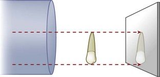
Good image making with appropriate equipment consists in the control of three variables: exposure, film or digital sensor position, and beam angulation. A good radiographic image for endodontic diagnostic and treatment purposes is obtained when the center of the x-ray beam passes through the apex and projects the tooth on the receptor film or sensor at a right angle (
Exposure
Always follow the recommended exposure settings provided by the manufacturer of the radiographic equipment. For conventional film, the film type and speed must also be considered. Underexposure results in the loss of details such as the periodontal ligament space and lamina dura around the apex (
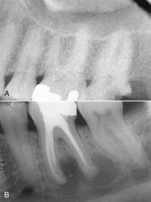
Overexposure tends to make normal structures appear pathologic. Radiolucency is observed in areas such as the cervical regions of teeth just above crestal bone, often referred to as cervical burnout, which resembles caries. There can also be loss of detail owing to excessive contrast in the film (
Film/Sensor Position
If a film packet or digital sensor is not completely behind the tooth to be studied, the tooth or portion of interest will not be on the image. In endodontics, the area of interest is almost always the apex (
FIGURE 2-4 Radiograph that fails to capture the root apices. Use on an increased angulation cannot compensate for this error.
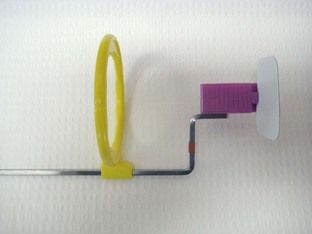
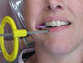
FIGURE 2-6 The Rinn XCP in place for exposure of a mandibular molar. Note how the bite block device holds the film at full depth. The upper edge of the film is even with the occlusal plane.
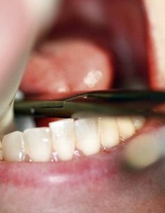
The major challenge during root canal treatment is to make accurate images while the dental dam is in place.
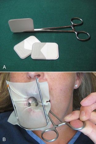
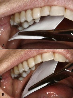
FIGURE 2-7 A, Hemostat holding the film or sensor. B, If the dental dam were in place, the hemostat could function like the film holder.

CLINICAL PROBLEM
Problem
Even with a hemostat/holder, the patient is unable to keep the film deep enough to capture the apices of a mandibular molar on a preoperative image.
Solution
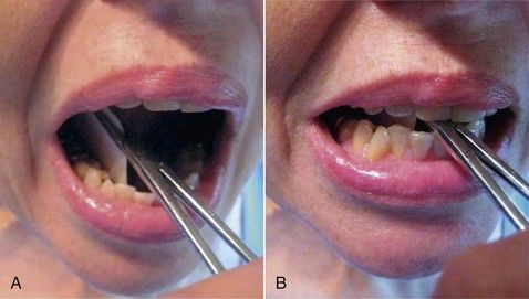
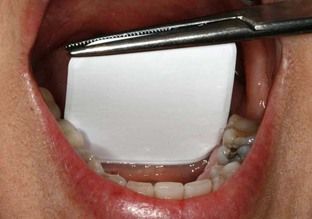
The film is placed in position with the hemostat/holder, and the patient is instructed to bite together. This will force the film/sensor downward to the proper depth, and at the same time the musculature of the floor of the mouth will relax (


CLINICAL PROBLEM
Problem
The patient has a narrow mandibular arch which makes placement of the film packet/sensor difficult for imaging the anterior teeth.
Solution
A conventional film packet can be bent at the edges to allow placement in the narrow space (
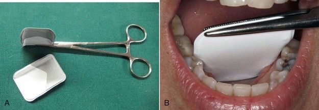
FIGURE 2-9 A, Standard sized film packet can be adapted to variable anatomic situations by bending the sides or corners. This will leave a line on the resultant image. Do not place the bend where it will interfere with the desired image of the tooth. B, A standard sized film adapted to a narrow arch.
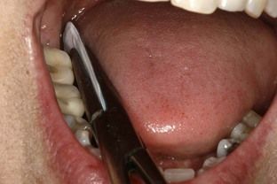
FIGURE 2-10 The anatomy of the lingual space is usually ideal for placement of the film or sensor parallel to the tooth.


CLINICAL PROBLEM
Problem
The patient has a muscular tongue and has a difficult time maintaining the film in position behind the anterior teeth, even though the tongue can be depressed.
Solution
Position the film/sensor using the hemostat/holder. Instruct the patient to maintain the handle of the hemostat/holder in contact with an incisor to the side as the hemostat exits the mouth. This will usually work with or without the dental dam in place but may require anesthesia (

Maxillary teeth are always a greater challenge in imaging because of the limited depth of the palatal vault and the anatomic lack of parallelism between the long axes of the teeth and the surface of the palate. To counter this, it is not necessary to have the film in contact with the tooth. For maxillary imaging, having the film or sensor in contact with the crowns (
Stay updated, free dental videos. Join our Telegram channel
VIDEdental - Online dental courses


