Chapter 3
Problem Solving in Interpretation of Dental Radiographic Images
Problem-solving challenges and dilemmas relative to the interpretation of dental radiographic images addressed in this chapter are:
“The radiographic picture is only one means of diagnosis. It seems absurd for a dentist to bring to a diagnostician a radiographic picture and ask his opinion … the picture may show a tremendous area of rarefaction, but to use it as the sole means of diagnosis is unwise.”< ?xml:namespace prefix = "mbp" />
Within the scope of endodontics, radiographic images serve a double purpose: the confirmation of normality and the indication or details of pathosis. Radiographic images are produced by the differential absorption of radiation by mineralized tissues through which the x-ray beam passes before exposing the receptor film or digital sensor. There are only three types of tissues that can be identified routinely on dental radiographs: bone, enamel, and dentin. Cementum or a cementum-type material can be identified when it is reparative or regenerative. Normal radiographic details and appearance are learned by correlating the knowledge of the physical anatomy of structures discussed in
Deviations from normality include radiographic changes in the anatomy of the teeth and bony structures. Most often, changes are represented as radiolucency or loss of mineralized structure, as in the case of caries, resorption, or infrabony periodontal defects.
Evaluation of Tooth Anatomy: Problem Prevention
The process of radiographic interpretation should begin with examination of the teeth. Assessment is limited in all areas of dentistry by the fact that the intraoral radiograph is a two-dimensional representation of three-dimensional objects. For example, even with well-made digital or film images, it is rarely possible to confirm or rule out the presence of a second canal in the mesial buccal root of a maxillary molar. Three-dimensional radiography is available in dentistry in the form of cone-beam computed tomography (CBCT),
Once a quality radiographic film is obtained, knowledge of dental anatomy is crucial for extrapolating two-dimensional representations into three-dimensional mental images. For example, anatomic examination of mandibular molar roots teaches that these roots are narrow in the mesial-distal dimension and very wide in the buccal-lingual dimension. A very wide root buccal-lingually will appear narrow on an optimal clinical radiograph. If the radiograph is made using variable angulations of the radiation beam (from the mesial or distal), the root will appear wider.
One objective of tooth evaluation will be to confirm anatomic form and any variations: it is sometimes possible to see two roots on a mandibular canine (
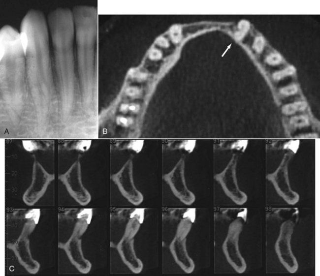
FIGURE 3-1 A, Mandibular canine with a bifurcated root. B, Another case of a mandibular canine investigated using cone-beam computed tomography (CBCT); occlusal view (arrow indicates tooth being evaluated). C, Proximal view of the two-rooted canine tooth using CBCT. Note sections 94 to 97; not only do they provide a good view of the two roots and two canals, but they also provide valuable information as to the location of the lingual canal and the challenges faced in access opening and orifice location.
Teeth that may be indicated for root canal treatment should be examined for relative length, the number of roots, calcification of canals, and general morphology. Once assessment has been completed, anatomy confirmed, and treatment initiated, canal morphology should be clearly visualized in the mind of the clinician and retained throughout treatment. Variations in the anatomy of posterior teeth such as the mandibular first molar are seen routinely (
The number of roots treated should be noted in each case of a previously treated tooth, as well as the quality of treatment (length of fill, density of fill, shape of canal, etc.). Although no abnormal changes may be found radiographically, the tissue remaining in uncleaned canals can give rise to symptoms of thermal sensitivity, percussion sensitivity, and spontaneous pain. Any teeth found to have poor or questionable root canal treatment could be possible sources of symptoms and potential candidates for treatment revision. Further clinical examination of these teeth would be indicated.

CLINICAL PROBLEM
Problem
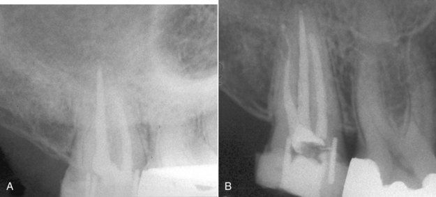
A 53-year-old male with a current history of acute pain to heat stimulation in the maxillary right posterior area was evaluated for treatment. The periapical film indicated that the second molar had past root canal treatment, but no carious lesions were seen radiographically or upon clinical exam. There was no evidence of periapical pathosis (
Solution
Routine sensibility tests were performed. The maxillary right first molar and two premolars responded normally to cold but did not respond to heat. The second molar responded abnormally to heat, with lingering pain. The patient stated this was the pain he had been experiencing. Examination of the radiograph revealed that the treated canals appeared asymmetrically located to the mesial of the root with respect to the overall morphology of the root anatomy. An untreated canal was suspected in the distal buccal root. Following access opening, the canal was identified, cleaned, shaped, disinfected, and obturated (see
A similar case is seen in
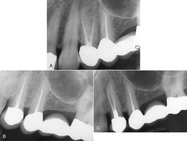
FIGURE 3-4 A, Initial radiograph of the maxillary left first premolar with heat sensitivity. B, Second view angulated slightly from the distal. Note the small bulge in the gutta percha extending mesially in the coronal third. C, Posttreatment image indicating a previously untreated canal.
(Courtesy Dr. Ryan Wynne.)

Radiographic Changes Associated With Dental Caries
The radiographic appearance of dental caries is basic to all dental education, and ample resources exist in the dental literature for further reading on detecting dental caries on routine radiographic surveys.
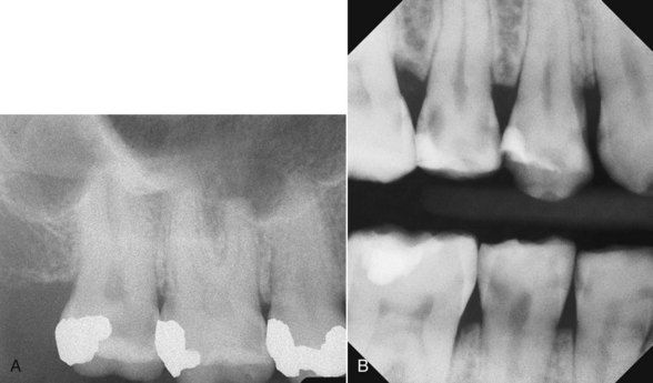
FIGURE 3-5 A, Carious exposure of mesiobuccal pulp horn in a maxillary second molar. B, Bitewing digital radiograph showing the location and extent of dental caries.
Carious lesions that appear near pulp horns also are likely to be carious exposures upon excavation. Demineralization of dentin that occurs in the process of caries is progressive and lacks a clear clinical or radiographic border. Most carious lesions extend deeper into the dentin than what can be ascertained radiographically.
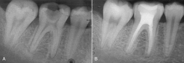
FIGURE 3-6 A, Caries near mesiobuccal pulp horn. B, Excavation revealed carious exposure and necrotic pulp. Root canal treatment was indicated.
For many teeth with large carious lesions, there may be no history of symptoms, and sensibility tests may provide normal responses (
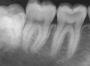
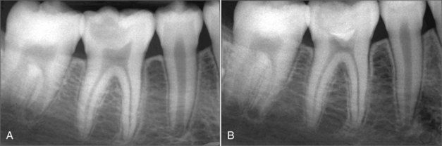
FIGURE 3-8 A, Large occlusal carious lesion in a 10-year-old patient. B, 12 month re-evaluation after vital pulp therapy using mineral trioxide aggregate (MTA) for a direct pulp cap. The patient was asymptomatic and the tooth responded normally to sensibility tests.
(Courtesy Dra. Silvina Díaz.)
The decision to treat a tooth endodontically can sometimes be influenced by the economic situation of the patient; successful vital pulp therapy could avoid additional expense. If it fails, the patient will still be able to receive root canal treatment (
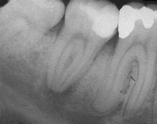
FIGURE 3-9 Pulpal necrosis and periapical pathosis following vital pulp therapy. Endodontic treatment was then indicated.
The radiographic appearance of recurrent decay is most often obvious at the margins of existing restorations. Caries beginning at the depth of a previous caries excavation will almost invariably involve the pulp (
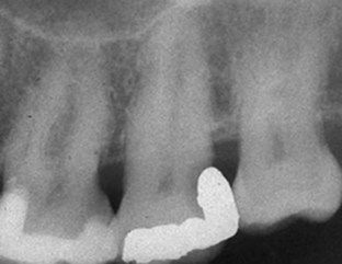
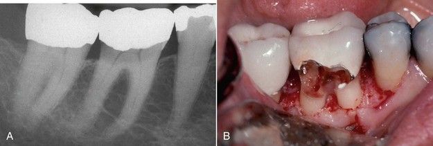
FIGURE 3-11 A, Recurrent caries under the buccal (or lingual) margin of crown. B, Clinical view of excavated caries shown in A.

CLINICAL PROBLEM
Problem
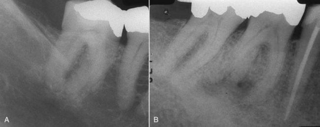
A 57-year-old male patient was examined for the chief complaint of recurrent spontaneous pain in the mandibular right teeth (
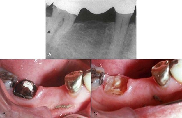
FIGURE 3-12 A, Radiograph of the abutment teeth of a mandibular right posterior bridge. Note the caries at margins of the crown on second molar. B, Following bridge removal, gross caries was found to involve the entire clinical crown on the molar abutment. C, Gross caries excavated. There is no clinical crown remaining.
Solution
The diagnosis centered on the mandibular second molar, since all other teeth were ruled out as having normal pulps. A shepherd’s hook explorer (No. 23) was placed under the solder joint immediately anterior to the crown of the second molar. Lifting the bridge with the explorer confirmed that the bridge was loose on this tooth but well retained on the second premolar. Not only was vertical mobility observed, but bubbles appeared in the saliva along the margins of the crown as the bridge was elevated and reseated. The decision was made to cut the bridge distal to the second premolar. Gross caries was found to have undermined the entire clinical crown of the second molar (see

Radiographic Changes Associated With Tooth Fractures
Coronal Fractures
Radiographically, the most commonly observed fracture is the posttraumatic image of an anterior tooth with coronal tooth loss (
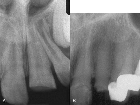
FIGURE 3-13 A, Typical traumatic coronal fracture of maxillary incisor in a young person. Note open apex. B, An anterior crown fracture in an elderly patient. Note calcification of canal.
Coronal fractures in posterior teeth generally occur in a mesial–distal orientation (
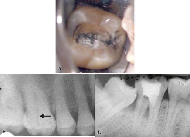
FIGURE 3-14 A, Coronal fractures in posterior teeth tend to be mesial-distal in direction. B, Unusual buccolingual fracture in maxillary molar crown is visible on radiograph. C, Mandibular molar with coronal fracture extending to a level below the furcation; note bone loss. The patient did not have evidence of periodontal disease in other areas of the dentition.
Midroot Fractures
Trauma can also result in midroot fractures. If the fracture occurs just submarginally, the crown will be extremely mobile (
Vertical Root Fractures
Vertical root fractures are a frequent cause of tooth loss almost unique to root-treated teeth. A second unique feature of this problem is the consistent location of the crack lines on the midfacial/buccal or 180 degrees on the midlingual/palatal regions of most roots. Occasionally a root is found with fractures in both positions. Lack of separation of the fractured segments of the root makes vertical root fractures seldom visible radiographically. The characteristic radiographic change is in the adjacent bone, which is the result of bone resorption along the fracture line. Early changes are typified by lateral widening of the periodontal ligament space. Often there is no apical involvement. As bone resorption continues, a distinct lateral radiolucency develops parallel to the root surface (
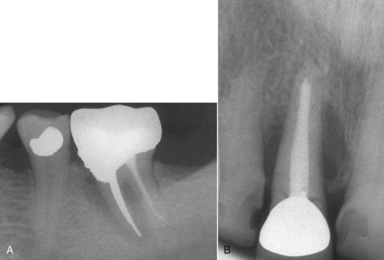
FIGURE 3-16 A, A vertical root fracture is not usually visible on a radiograph. B, Lateral bone loss associated with a vertical root fracture.
When a fracture is visible and significant separation of the fractured segments of the root has occurred, the fracture has probably been present for a long time (
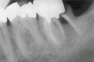
FIGURE 3-17 Wide separation of root segments after vertical root fracture. Clinically, deep narrow periodontal defects are found on both buccal and facial surfaces in cases of complete root fracture.
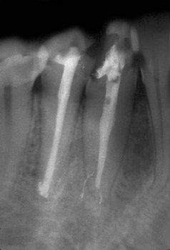
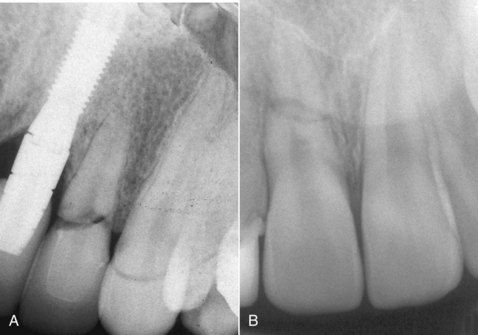
FIGURE 3-18 Vertical root fracture in a second premolar caused by excessive condensation pressure during obturation. Note the widened periodontal ligament space on the distal from crestal bone to the apex. Lateral and longitudinal extrusion of filling materials is a possible sign that fracture occurred during the procedure.
Stay updated, free dental videos. Join our Telegram channel
VIDEdental - Online dental courses


