The Third Stage of Comprehensive Treatment
Finishing
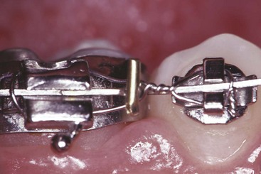
By the end of the second stage of treatment, the teeth should be well aligned, extraction spaces should be closed, tooth roots should be reasonably parallel, and the teeth in the buccal segments should be in a normal Class I relationship. In the Begg technique, major root movements of both anterior and posterior teeth still remained to be done in Stage 3 to obtain root paralleling at extraction sites and proper torque and axial inclination of tipped incisors, and this was accomplished with auxiliary springs. In the modern modified Begg technique, using Tip-Edge brackets, auxiliary springs are augmented with rectangular archwires in Stage 3 (Figure 16-1).
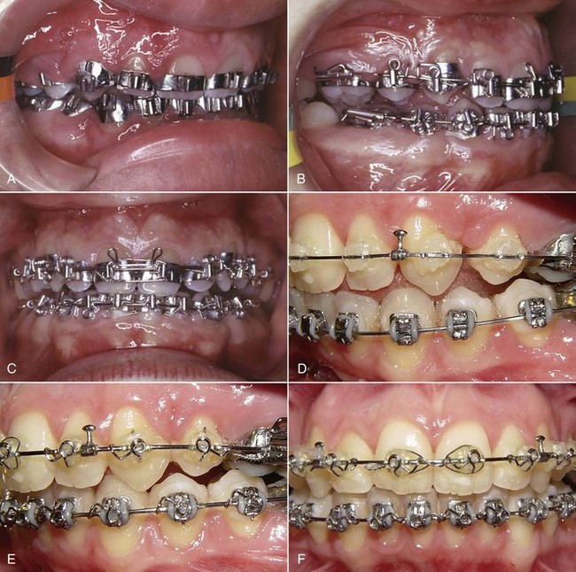
FIGURE 16-1 Stage 3, finishing, in a patient treated in the 1970s with classic Begg technique. A, The Begg appliance in a patient who has had premolar extraction and space closure and is ready for the finishing stage of treatment. Note the ribbon arch bracket turned upside down from the way Edward Angle positioned it. Archwires are pinned into place. B, Uprighting springs and a torquing arch in place. The uprighting springs (used here on lateral incisors, canines, and second premolars) fit into the vertical tube portion of the bracket and are hooked underneath the base archwire to create root-positioning moments. An auxiliary torquing arch is threaded over the archwire and places a lingual force against the tooth above the bracket slot. C, Anterior view of the torquing arch and uprighting springs. D, The finishing stage of treatment with Tip-Edge, a modern extension of the Begg appliance, after tipping the teeth to close space and retract protruding incisors in this Class II patient who had upper premolar extractions. E, Auxiliary uprighting springs (seen here on the maxillary lateral incisor, canine, and second premolar) are used for root positioning, with a different type of spring for the incisors where torque is desired, and a rectangular archwire serves as a template and prevents overcorrection. Note the improvement in both inclination of incisors and root paralleling at the extraction sites. F, Frontal view. Note that the auxiliary spring for torque to incisors now is quite different from the Begg torquing arch or its equivalent for use as an edgewise auxiliary (see Figure 16-6).
Although many variations are inevitable to meet the demands of specific cases, it is possible to outline a logical sequence of archwires for continuous arch edgewise technique, and this has been attempted in Box 16-1. The sequence is based on two concepts: (1) that the most efficient archwires should be used, so as to minimize clinical adjustments and chair time, and (2) that it is necessary to fill (or nearly fill) the bracket slot in the finishing stage with appropriately flexible wires to take full advantage of the modern appliance. Appropriate use of the recommended finishing archwires and variations to deal with specific situations in finishing are reviewed in some detail below. Similar recommendations and variations in the first two stages of treatment have been provided in the two previous chapters.
Adjustment of Individual Tooth Positions
When it becomes apparent that a bracket is poorly positioned, usually it is time-efficient to rebond the bracket rather than place compensating bends in archwires. This is particularly true when the inclination of the tooth is incorrect, so that angulated step bends in wires would be required. After the bracket is rebonded, however, a flexible wire must be placed to bring the tooth to the correct position. Rectangular steel finishing wires are too stiff in bending for tooth positioning, for both the 18- and 22-slot appliances. In the 18-slot appliance, 17 × 25 beta-titanium (beta-Ti) usually is satisfactory; in the 22-slot appliance, 21 × 25 martensitic nickel–titanium (M-NiTi) often is the best choice when high flexibility of the archwire is needed—21 × 25 beta-Ti is too stiff in bending. Minor in–out and up–down adjustments, typically to obtain perfect canine interdigitation and level out marginal ridge heights, can be obtained simply and easily by placing mild step bends in the finishing archwires. The principle is the same as when brackets are rebonded: these bends should be placed in a flexible full-dimension wire, the next-to-last wire in the typical sequence shown in Box 16-1. Obviously, any step bends placed in the next-to-last wire (17 × 25 beta-Ti or 21 × 25 M-NiTi) must be repeated in the final wire that is used for torque adjustments (17 × 25 steel or 21 × 25 beta-Ti). Note that NiTi archwires (both M-NiTi and A-NiTi) are not recommended for expression of torque. They simply do not have the torsional properties to be effective (see Chapter 10).
Although the position of a V-bend relative to the adjacent brackets is critical in determining its effect, the position of a step bend is not a critical variable. It makes no difference whether a step bend is in the center of the interbracket span or offset to either side.1
Midline Discrepancies
As with any discrepancy at the finishing stage, it is important to establish as clearly as possible exactly where the discrepancy arises. Although coincident dental midlines are a component of functional occlusion—all other things being equal, a midline discrepancy will be reflected in how the posterior teeth fit together—it is undesirable esthetically to displace the maxillary midline, bringing it around to meet a displaced mandibular midline. If a dental midline discrepancy results from a skeletal asymmetry, it may be impossible to correct it orthodontically, and treatment decisions will have to be made in the light of camouflage versus surgical correction (see discussion in Chapter 7).
Fortunately, midline discrepancies in the finishing stage usually are not this severe and are caused only by lateral displacements of maxillary or mandibular teeth accompanied by a mild Class II or Class III relationship on one side. In this circumstance, the midline often can be corrected by using asymmetric Class II (or Class III) elastic force. As a general rule, it is more effective to use Class II or Class III elastics bilaterally with heavier force on one side than to place a unilateral elastic. However, if one side is totally corrected while the other is not, patients usually tolerate a unilateral elastic reasonably well. It is also possible to combine a Class II or Class III elastic on one side with a diagonal elastic anteriorly to bring the midlines together (Figure 16-2). This approach should be reserved for small discrepancies. Prolonged use of Class II or Class III elastics during the finishing stage of treatment should be avoided. Coordinated steps in the archwires also can be used to shift the teeth of one arch more than the other.2
An important consideration in dealing with midline discrepancies is the possibility of a mandibular shift contributing to the discrepancy. This can arise easily if a slight discrepancy in the transverse position of posterior teeth is present. For instance, a slightly narrow maxillary right posterior segment can lead to a shift of the mandible to the left on final closure, creating the midline discrepancy. The correction in this instance, obviously, must include some force system to alter the transverse arch relationships (usually careful coordination of the maxillary and mandibular archwires, perhaps reinforced by a posterior cross-elastic). Occasionally, the entire maxillary arch is slightly displaced transversely relative to the mandibular arch so that with the teeth in occlusion, relationships are excellent, but there is a lateral shift to reach that position. Correction again would involve posterior cross-elastics but in a parallel pattern (i.e., from maxillary lingual to mandibular buccal on one side and the reverse on the other side; see Figure 16-2).
Tooth Size Discrepancies
Tooth size discrepancy must be taken into account when treatment is planned initially, but many of the steps to deal with these problems are taken in the finishing stage of treatment. Reduction of interproximal enamel (stripping) is the usual strategy to compensate for discrepancies caused by excess tooth size. When the problem is tooth size deficiency, it is necessary to leave space between some teeth, which may or may not ultimately be closed by restorations. As a general guideline, a 2 mm tooth size discrepancy noted from Bolton analysis is the threshold for clinical significance3 (i.e., that large a discrepancy predicts that steps to deal with it will be required during treatment), but at the finishing stage, you get to see how accurate the prediction really was.
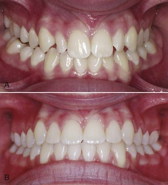
Tooth size problems often are caused by small maxillary lateral incisors. Leaving a small space distal to the lateral incisor can be esthetically and functionally acceptable, but a composite resin buildup usually is the best plan for small incisors (Figure 16-3). Precise finishing is easier if the buildup is done during the finishing stage of the orthodontic treatment. This can be accomplished simply by removing the bracket from the small tooth or teeth for a few hours while the restoration is done, then replacing the bracket and archwires (but bonding to a laminate may damage the surface, so a buildup to establish tooth size is okay, but a laminate should be delayed). If the restoration is delayed until the orthodontics is completed, it should be done as soon as possible after the patient is in retention. This requires an initial retainer to hold the space, and a new retainer immediately after the restoration is completed. The main reason for waiting until after the orthodontic appliance has been removed would be to allow any gingival inflammation to resolve itself.4
More generalized small deficiencies can be masked by altering incisor position in any of several ways. To a limited extent, torque of the upper incisors can be used to compensate: leaving the incisors slightly more upright makes them take up less room relative to the lower arch and can be used to mask large upper incisors, while slightly excessive torque can partially compensate for small upper incisors. These adjustments require third-order bends in the finishing archwires. It is also possible to compensate by slightly tipping teeth or by finishing the orthodontic treatment with mildly excessive overbite or overjet, depending on the individual circumstances.5
Root Paralleling
In the Begg technique (see Figure 16-1), the moments necessary for root positioning were generated by adding auxiliary springs into the vertical slot of the Begg (ribbon arch) bracket. In most instances, a heavier (20 mil) archwire replaced the 16 mil archwire used as a base arch up to that point to provide greater stability. Root paralleling was accomplished by placing an uprighting spring in the vertical slot and hooking it beneath the archwire. Since root-paralleling forces are also crown-separating forces, it was important to tie the crowns together across extraction sites. In the modified Begg technique using the Tip-Edge appliance, root paralleling is accomplished with uprighting springs, very much as it was with traditional Begg treatment. The rectangular wire is used primarily for torque (faciolingual root movement), not the mesiodistal root movement needed for root paralleling after teeth were allowed to tip during space closure.
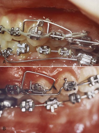
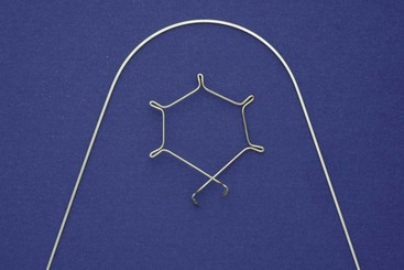
Although superelastic NiTi (A-NiTi) wires perform much better than elastic NiTi (M-NiTi) wires in alignment, this is not true of their performance as rectangular finishing wires. The great advantage of A-NiTi is its very flat load-deflection curve, which gives it a large range. In the finishing stage, however, appropriate stiffness at relatively small deflections, rather than range, is the primary consideration. A-NiTi wires usually deliver less force than their M-NiTi counterparts (this will depend on how the manufacturer manipulated the wire [see Chapter 9]), and if rectangular A-NiTi is used in the finishing stage, the wire’s properties in both bending and torsion must be considered in the choice of the wire. M-NiTi almost always is the better choice for rectangular nickel–titanium wires. Occasionally, a severely tipped tooth will be encountered (almost always because of a bracket positioning error), and a longer range of action is needed. This may indicate using a rectangular A-NiTi wire initially, then M-NiTi. An alternative, usually practical only if the edgewise brackets have a vertical slot or tube, is an auxiliary root-uprighting spring (Figure 16-4).
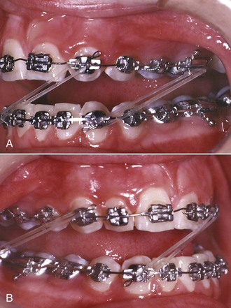
A root-paralleling moment is a crown-separating moment in edgewise technique just as it is in Begg or any other technique. It is important to remember this effect. Either the teeth must be tied together or the entire archwire must be tied back against the molars (Figure 16-5) to prevent spaces from opening. Not only extraction sites but also maxillary incisors must be protected against this complication. When a full-dimension rectangular wire is placed in the maxillary arch, spaces are likely to open between the incisors in nonextraction as well as extraction cases. Tying the maxillary incisors together, which can be done conveniently with a segment of elastomeric chain from the mesial bracket of one upper lateral incisor across to the mesial bracket of the other, is necessary during finishing.
Torque
Lingual Root Torque of Incisors
If protruding incisors tipped lingually while they were being retracted, lingual root torque as a finishing procedure may be required. In the Begg technique, the incisors are deliberately tipped back during the second stage of treatment, and lingual root torque is a routine part of the third stage of treatment. Like root paralleling, this is accomplished with an auxiliary appliance that fits over the main or base archwire. The torquing auxiliary is a “piggyback arch” that contacts the labial surface of the incisors near the gingival margin, creating the necessary couple with a moment arm of 4 to 5 mm (see Figure 16-1). These piggyback torquing arches can be used in edgewise technique in the same way (see Figure 14-30, D). Although they come in a number of designs, the basic principle is the same: the auxiliary arch, bent into a tight circle initially, exerts a force against the roots of the teeth as it is partially straightened out to normal arch form (Figure 16-6).
A torquing force to move the roots lingually is also, of course, a force to move the crowns labially (see Figure 15-24). In a typical patient with a Class II malocclusion, anchorage is required to maintain overjet correction while upper incisor roots are torqued lingually. For that reason, Class II elastics are likely to be necessary when active lingual root torque is needed during the final stage of Class II treatment.
With the 22-slot appliance, full-dimension steel rectangular wires are far too stiff for effective torquing (see Figure 9-11). If incisors have been allowed to tip lingually too much, as can happen in the correction of maxillary incisor protrusion, correcting this merely by placing a rectangular steel archwire is not feasible./>
Stay updated, free dental videos. Join our Telegram channel
VIDEdental - Online dental courses


