Chapter 15
Osseointegrated implants
Introduction
Prosthodontics has become one of the more exciting areas in dentistry due to the development of two disruptive technologies: osseointegrated implants and cone-beam computed tomography (CBCT). Although the American Academy of Oral and Maxillofacial Radiology (AAOMR) recommends that some form of cross-sectional imaging be used for preimplant assessment1 not all jurisdictions demand this; the European Association for Osseointegration (EAO) does not.2 It declares that the “choice of technique is based on the lowest dose giving the required diagnostic information.” Nevertheless, this report did not include CBCT compelling the European Academy of Dental and Maxillofacial Radiology (EADMFR) to issue its “Basic principles for the use of dental cone beam CT.”3
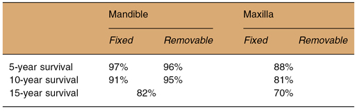
In many communities, the osseointegrated implant, which will now be simply referred to as the “implant,” has become the treatment of choice for replacement of one or more missing teeth. Current implant placement can be successful when the cases have been properly selected and the procedure properly executed. A recent systematic review reported survival of implants placed in the completely edentulous mandibular and maxillary arches.4 The results are summarized in Table 15.1.
Table 15.1. Summary of the survival of implants from the systematic review of implants in completely edentulous arches
Although training for implants is clearly a postgraduate activity in most jurisdictions, this training includes an in-depth understanding in the field of oral and maxillofacial radiology, dentoalveolar surgery, and the principles of modern prosthodontics. Because different specialties are involved, a team approach is commonly required to optimize planning.
Success of the dental implant depends largely on the thorough preoperative assessment of the patient’s medical and oral condition. With regard to the latter, the oral and maxillofacial radiologist’s role is superlative. This requires assessment of the alveolar bed on and around the prospective implant. The anatomy, quantity, and quality of alveolar bone determines the suitability for implant placement and the appropriate size, length, and position of the implant (Figures 15.1, 15.2). All implant planning is made with some form of radiographic investigation. The range of imaging methods for implant assessment varies considerably. It can be anything from simple intraoral periapical radiography to helical computed tomography (HCT) and CBCT (Table 15.2). Other imaging methods such as magnetic resonance imaging (MRI) and ultrasonography (US) have been explored with limited success and will not be considered further.
Table 15.2. A comparison of the main features of 6 imaging modalities that can be employed in preimplant assessment
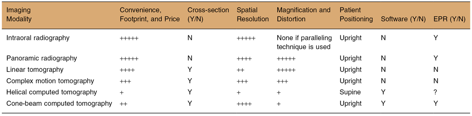
Key: EPR, electronic patient record; N, no; Y, yes.
The number of + (+ to +++++) indicates an increased facilitation of quality of a feature.
Figure 15.1. The panoramic and cross-sectional reconstructions of cone-beam computed tomography of two cases (a,b and c,d) display edentulous alveolar processes with good bone height and quality for both jaws.
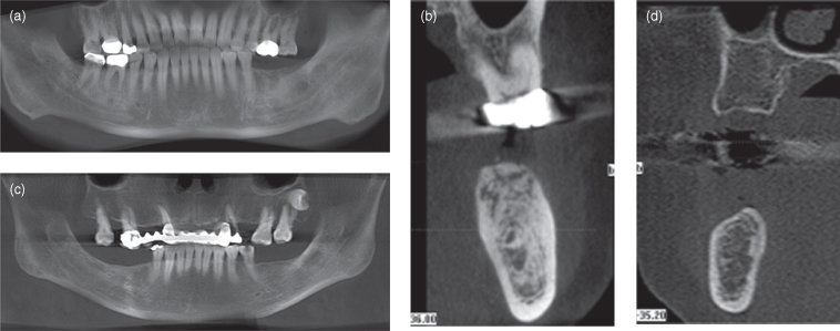
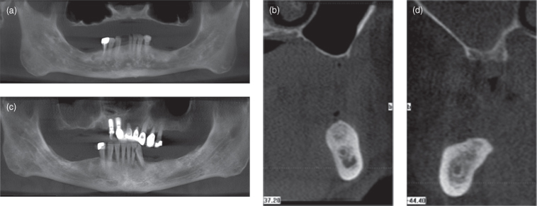
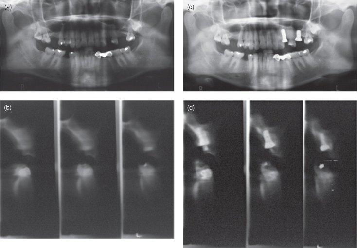
Figure 15.2. The panoramic and cross-sectional reconstructions of cone-beam computed tomography of two cases (a,b and c,d) display edentulous alveolar processes with reduced bone height and quality for both jaws. Note that for both cases the floor of the maxillary antrum is separated from the oral mucosa by only a cortex, This is particularly apparent in b.
Because conventional intraoral and panoramic radiographs can provide only anatomical information in the 2-dimensional (2-D) mesiodistal plane, some form of tomographic or 3-dimensional (3-D) imaging is needed to demonstrate anatomy in the buccolingual plane. This enables measurement of the width of the alveolar bed. These images can be obtained in an analog (film) or in a digital format. Each has its own measuring and calibration system to ensure relatively accurate measurement. Projection magnification, which varies widely, particularly for panoramic radiography, has to be accounted for.
To maximize the chance for successful osseointegration, implants have to be placed accurately in the alveolar bed in a 3-D space. The objective is to have an adequate area of contact between the implant and sound alveolar bone, while avoiding anatomical hazards such the as mandibular canal, incisive canal, maxillary antrum, and submandibular fossa. Although Vazquez et al. have shown that panoramic radiography can be considered a safe preimplant assessment modality for routine posterior mandibular implants “if a safety margin of at least 2 mm above the mandibular canal is respected,”5 buccal or lingual cortical plate perforation can occur easily without adequate appreciation of the buccolingual dimension (Figure 15.3). Therefore, this objective can be achieved only when the anatomy of the alveolar bed is clearly visualized in a multiplanar or a 3-D format. Many anatomical hazards, mandibular and incisive canals, foramina, concavity of cortical plate, and thin alveolar ridges cannot be demonstrated with conventional radiography; these will be considered at the end of this chapter. Therefore, cross-sectional imaging is required. The cross-sectional imaging modalities that have been applied to preimplant assessment are linear tomography, complex-motion tomography, HCT, and CBCT.
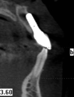
Figure 15.3. Cone-beam computed tomography (CBCT) displaying perforation (indeed, replacement) of the labial cortex by the implant. This implant has failed.
LINEAR TOMOGRAPHY
This type of tomography is not recommended by the AAOMR for implant imaging.1 Linear tomography has been reported to be subject to distortion.6 Some dental panoramic machines include linear tomography. Linear tomography demonstrates the anatomy of a section of the jaws in a flat buccolingual plane. Typical slice thickness is about 3–6 mm and each examination series would consist of three to four tomographic cuts covering a one- to two-teeth region. There is typically a magnification of 1.4. Special calibrated rulers or magnified overlay transparence are used to measure the exact dimension of the jawbone on the film.
The general spatial resolution of the images is poor (Figure 15.4), but it still provides an image of sufficient quality to show obvious anatomical features, such as the maxillary sinus and the submandibular fossa. When no other superior imaging method is available, linear tomography is superior to conventional 2-D imaging alone.
Figure 15.4. Linear tomography of implant site preimplant (a,b) and postimplant (c,d) assessment. Views a and c are panoramic radiographs. Views b and d are linear tomographs. The spatial resolution is poor.
The panoramic radiographic machine has to be adjusted to perform linear tomography with a custom-made head positioning device such as a jaw registration block. The procedure is complicated and technique-sensitive because the imaging plane is determined by the exact head positioning. Unless very experienced, most clinicians find this examination troublesome. The inferior image quality and complicated procedure have limited its utility.
COMPLEX MOTION TOMOGRAPHY
Complex motion tomography includes spiral and hypocycloidal tomography. Bou Serhal et al. demonstrated that their spiral conventional tomographic unit displayed very good localization of the mandibular canal “if the clinician takes into consideration the maximal overestimation encountered with this technique and if precautions are taken during the radiographic procedure, e.g., positioning of the head and immobility during scanning.”7 Hypocycloidal conventional tomography is reported to create the best blurring of objects outside the focal trough. Spiral conventional tomography has been demonstrated to provide very good display of the mandibular canal. A more recent report indicated that spiral tomography significantly changed presurgical treatment plans.8
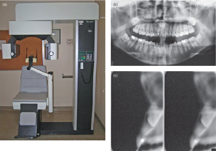
Complex motion tomography was most frequently used for preimplant assessment, prior to the advent of CBCT. The Scanora (Figure 15.5) and Cranex both use spiral tomography, whereas the CommCat uses hypocycloidal motion. Their complex motion produces very even blurring of objects outside the focal trough, thus enhancing the clarity of the structure of interest. The Scanora uses a rotating anode X-ray tube, which has a much higher loading factor and a smaller focal spot. The quality of these sectional images is significantly better than the linear ones. With a larger swing angle, the slice thickness can be reduced to 2 mm. A typical examination series would cover a one- to two-teeth region. The magnification factor for Scanora in buccolingual tomography is 1.7. A typical series of projections for a one- to two-teeth region takes around 2 minutes. The spiral movement of the film cassette holder in front of the patient’s face can induce dizziness in sensitive patients. Patients are advised to close their eyes during exposure because any patient movement during exposure would cause unacceptable movement artifacts.
Figure 15.5. Scanora unit (a). The panoramic radiograph (b) and two transverse sections (c) of an unerupted maxillary tooth.
Both linear and complex-motion (especially spiral) tomography can be acquired using an analog (film) or a digital system. The radiation dose for one or two sections is similar to one panoramic radiograph. Multiple implant sites require multiple exposures. A full mouth assessment would take up to 15 projections and would be very time consuming. Therefore, complex motion tomography is best used for planning of relatively simple implant cases that need only one or two implants.
HELICAL COMPUTED TOMOGRAPHY
HCT requires a dedicated high amperage power line in order to sustain the high tube current and long exposure. Special cooling of the CT room is needed to remove the heat generated by the tube head. Therefore, it is best situated in a hospital. The basics of HCT are discussed in Chapter 4.
The major advancements in HCT are in large part due to improved computer power and upgraded image sensors. The scan time can be very rapid. The scan for the maxillofacial region for implant planning in a 64-slice machine is around 5–10 seconds. The reconstruction time is only a couple of seconds; by the time the patient has left the HCT table, the images are ready for viewing. The workstation of the machine, besides storing patient files, is also loaded with a wide range of image viewing software, such as multiplanar reformatting, 3D reconstruction using surface shade display, or volume rendering methods. Most of these are introduced in Chapter 4.
The original viewing software for implant planning is called Dentascan (General Electric, Pittsfield, USA), which is still extensively used. This is a form of multiplanar reformatting, which reformats sectional images perpendicular to the dental arches. The results are high-quality diagnostic images that are calibrated to life size and printed on films. The clinician can make measurements directly on films using a standard metric ruler to obtain accurate dimensional measurement of the alveolar bed and jawbones. Because the image is set to be perpendicular to the occlusal plane, measurement in an oblique plane is not possible.
All image data from HCT is stored in Digital Imaging and Communications in Medicine (DICOM) format. It was created by the National Electrical Manufacturers Association (NEMA, USA) to aid the distribution and viewing of medical images, such as CT, MRI, and US. This image file format is not compatible with ordinary personal computers. Special DICOM viewer software has to be included to view the files.
Some clinicians still prefer to have the CT images printed on analog format (films) for easy viewing. However, images once printed cannot be adjusted for window width and window level (see chapter 4). There is a loss of information in the transfer of data from the scanning computer to the printer. Unless frequently calibrated, the radiographic printer can lose its dimensional accuracy after repeated use. In time, the volume of CT films can grow considerably, complicating storage and easy file retrieval. Digital diagnostic images are best viewed digitally, that is using a computer monitor. Clinic layout must be changed to facilitate easy assess to a large, high-quality computer monitor both for dentist and patient viewing (see Chapter 2.).
Modern HCT provides high-quality sectional images with good spatial resolution. Its benefit is somewhat offset by relatively high radiation dose and high equipment costs. The typical radiation dose for an HCT is at least 100 times that of similar examination by linear or spiral tomography.2 Considering that implant treatment is for rehabilitation of dentition rather than for detecting life-threatening pathology, the high radiation dose imparted by HCT is rightly a concern for the clinicians and their patients.
Most HCT facilities are operated by medical radiologists and radiographers and give priority to medical patients. Some dental practitioners may find that the medical CT center has difficulty understanding the special needs of dental implant surgery. Unless there is good communication and understanding between the medical radiologist and referring dental practitioner, the full benefit of HCT may not be realized. For the best results, there should be zero gantry tilt and the patient’s occlusal plane should be vertical. It is difficult to assess and align the occlusal plane in an HCT supine setting. The head holder is rigid and not adjustable.
CONE-BEAM COMPUTED TOMOGRAPHY
CBCT scanners have been available for craniofacial imaging since 1999 in Europe and 2001 in the United States. At present, all major manufacturers of dental X-ray equipment have CBCT. Some machines are cone-beam only equipment (see Figure 5.5a); others are add-on extras onto standard panoramic radiographic machines (see Figure 5.5b). The hybrid machine offers the choice of a standard panoramic radiographic and a cone-beam volumetric scan. The basics of CBCT have been addressed in Chapter 5.
The/>
Stay updated, free dental videos. Join our Telegram channel
VIDEdental - Online dental courses


