Cone-Beam Computed Tomography
Anatomy
Sanjay M. Mallya and Sotirios Tetradis
Cone-beam computed tomographic (CBCT) imaging is an advanced imaging modality that provides excellent visualization of the dental hard tissues and osseous structures in three dimensions. CBCT imaging has become widely used over the last decade because it has multiple applications in dentomaxillofacial diagnosis. The anatomic coverage of CBCT imaging may be limited to the dentoalveolar arch or may extend to encompass a large part of the craniofacial skeleton. Clinicians who use CBCT imaging must be competent in recognizing radiographic manifestations of disease throughout the volume imaged. Similar to two-dimensional images, radiographic identification of abnormalities requires a thorough knowledge of the radiographic appearance of anatomic structures.
General Principles of Evaluation
Although the region of immediate diagnostic interest may be limited to a specific site, it is important to evaluate all structures imaged. Many instances have been reported of benign and malignant tumors being detected serendipitously—that is, in part of the volume unrelated to the reason for which the image was made. Accordingly, it is critical to evaluate the imaged volume systematically in the axial, coronal, and sagittal planes. The anatomic structures must be identified and, where applicable, the symmetry and continuity of the bony outlines assessed.
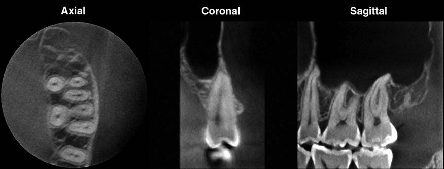
CBCT images are displayed as multiplanar reconstructions of the imaged structures in three orthogonal planes (Fig. 13-1). For ease of visualization, the imaged volume may have to be reoriented, for example, to align the midsagittal plane to correct for any slight positioning errors during image acquisition; this is particularly important when examining for symmetry of structures. Many software programs used for CBCT image visualization allow for reorientation of all three planes. It is useful to reorient the axial plane to facilitate viewing of specific structures—for example, parallel to the Frankfort plane when examining the skull base or parallel to the occlusal plane when examining the dentoalveolar arches. To decipher the complete morphology of the imaged region, it is critical to view the entire image volume in all three orthogonal planes. Depending on the diagnostic task, it may be necessary to make additional custom reconstructions in specific planes, such as cross sections to evaluate the teeth and dentoalveolar ridges. In any single section, the plane of section may be oblique and incomplete through an anatomic site and may cause the structure to appear abnormal.
Teeth and Supporting Structures
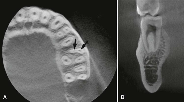
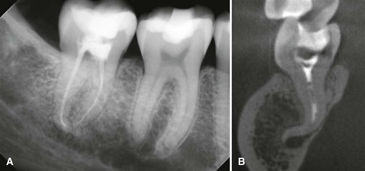
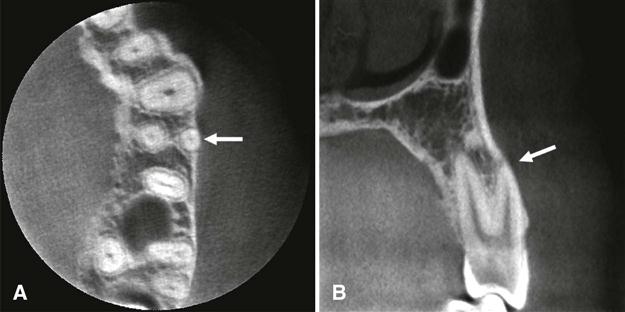
The detailed anatomy of the teeth and the supporting periodontium is best depicted on limited field-of-view (FOV) scans. Similar to intraoral radiographs, the teeth demonstrate a radiopaque enamel cap, a homogeneously radiopaque dentin, and radiolucent pulp chambers and pulp canals (see Fig. 13-1). As in periapical radiographs, cementum is typically not radiographically apparent because of the lack of radiographic contrast between cementum and dentin. Because CBCT scans provide three-dimensional information, they portray the morphology of the roots, pulp chambers, and pulp canals more accurately than intraoral radiographs. Thus a pulpal canal that is not evident in periapical radiographs owing to superimposition often can be clearly depicted on CBCT scans. CBCT imaging is particularly useful to evaluate multirooted teeth and roots with multiple pulp canals. The number and morphology of pulp canals and their course through the roots in all three planes can be examined. For multirooted teeth, reconstruction of the image volume along the long axis of each root may also be required. The individual canals are best identified on axial sections, whereas the course of the canal through the length of the root and its exit through the apex are typically assessed on coronal and sagittal sections (Fig. 13-2). Frequently, morphologic variations, such as root dilacerations in the buccolingual dimension, are not apparent on periapical and panoramic radiographs but are well demonstrated on CBCT examinations (Fig. 13-3). Detection of normal variations of the radicular and pulpal morphology is vital to endodontic treatment planning and presurgical assessment of the relationship of the roots to adjacent neurovascular structures. CBCT scans also reveal the proximity of the root surface to the cortical plates of the alveolar bone and detect anatomic variations, such as fenestrations or dehiscence defects (Fig. 13-4).
When viewing dentoalveolar structures, it is often useful to make cross-sectional reconstruction—slices in the buccolingual direction that are parallel to the long axis of the tooth. Additional curved planar reformatting can be used to generate a “panoramic” reconstruction, which also depicts the locations of the individual cross-sectional slices.
Maxilla and Midfacial Bones
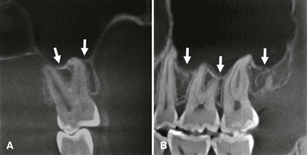
The maxilla and palatine bones form the upper jaw. The maxilla comprises a pyramidal-shaped body and four processes—alveolar, palatine, zygomatic, and frontal. The alveolar and palatine processes articulate in the midline to form the intermaxillary suture between the central incisors, best evaluated on coronal and axial sections. Examine the alveolar process, which forms the bone around the maxillary teeth, along with the maxillary teeth and supporting periodontal structures. In particular, owing to their three-dimensional nature, CBCT scans demonstrate the relationship of the molar and premolar teeth to the floor of the maxillary sinus better than periapical and panoramic radiographs. A common anatomic finding is pneumatization of the alveolar process by the maxillary sinus, which may invaginate between tooth roots (Fig. 13-5).
The palatine processes are thick horizontal bony projections that form the anterior three-fourths of the hard palate and the floor of the nasal cavity. The integrity and symmetry of the cortical bony contour are best visualized on coronal sections (see Plates 13-4 and 13-5). Disruption of the hard palate suggests developmental disturbances, such as a cleft palate. Areas of bony protuberances or tori are frequently noted, especially in the midline. Numerous nutrient canals also may be observed perforating the cortical outline of the hard palate on high-resolution scans.
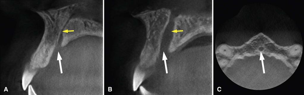
The incisive foramen is located in the midline on the anterior aspect of the palatine process, immediately palatal to the maxillary central incisors (Fig. 13-6; see Plate 13-7). Within this foramen are two lateral canals—the incisive canals or foramina of Stensen—that transmit the terminal branch of the descending palatine artery and the nasopalatine nerve. Occasionally, there may be two additional midline canals—the foramina of Scarpa, which transmit the nasopalatine nerves. The shape and size of the incisive foramen is appreciated on axial sections (see Plates 13-2 and 13-3). There is considerable variation in the size of the nasopalatine canal and incisive foramen. It is important to differentiate between a large incisive foramen and an incisive canal cyst because the latter can cause localized dilation of the canal or widening of the incisive foramen and may cause displacement of teeth (see Chapter 21).
Stay updated, free dental videos. Join our Telegram channel
VIDEdental - Online dental courses


