Chapter 10
Problem-Solving Clinical Techniques in Enlarging and Shaping the Root Canal
Problem-solving issues and challenges in enlarging and shaping the root canal system addressed in this chapter are:
“In attempting to assign the success or failure of operations upon diseased teeth to their proper causes, factors of the greatest importance are frequently left out of account, and the results ascribed to some agent which may have been entirely indifferent. One of these factors, which forms the very foundation of successful root-treatment, is the manner in which the mechanical cleansing of the canal is carried out.”< ?xml:namespace prefix = "mbp" />
Problem-solving principles in enlarging and shaping the root canal system are predicated on the guidelines presented in
Application of traditional techniques in canal enlarging and shaping using stainless steel root canal instruments has received volumes of attention historically.
Prevention of Procedural Errors in Canal Enlarging and Shaping Using Traditional Techniques and Stainless Steel or Nickel-Titanium Instruments
The safe and efficacious practice of endodontics, specifically root canal procedures, is based on both biological and clinical parameters, with prevention being the operative word. This discussion precludes a focus on management of problems. Most if not all can be prevented with a knowledgeable and thoughtful approach to providing care at all times. In the discussion of endodontic outcomes, only too often when cases fail, they are labeled as “endodontic failures,” or the “persistence of what is generically termed endodontic disease.”
Loss of Working Length
Loss of working length during cleaning and shaping is a common and frustrating procedural error. The problem is often only noted on the master-cone radiograph or when the master apical file (MAF) is short of the intended or initial working length. Even worse, it is often not noted until the canals are filled and a crown is placed. Too many times it is never noted (
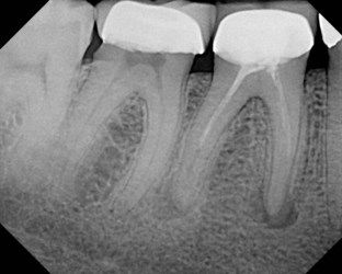
FIGURE 10-1 A 39-year-old presented with pain to biting on the mandibular first molar. He related that he could not understand why he was having pain; root canal treatment and a crown had been completed only 2 weeks prior to this painful episode. Note the incomplete root canal treatment with possible ledges in the mesial canals.

FIGURE 10-2 A, Preoperative radiograph showing significant curvature of the mesial canals, which should warn the clinician that ledging is more likely to occur if instrumentation is not performed cautiously. B, Master apical file radiograph shows that canals were instrumented larger than appropriate for size and curvature of mesial roots. Notice the loss of canal length and ledge formation. C, Mesial canals are fully ledged, and distal canal is partially ledged.
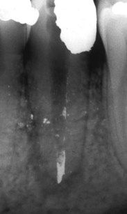
FIGURE 10-3 Packed amalgam particles in the apical extent of the canal block the apical 3 mm of the root canal.
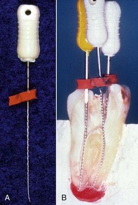
FIGURE 10-4 A, Improperly placed stop on a file can significantly change the accuracy of the working length and maintenance of canal length during enlarging and shaping. B, Cross-section of extracted tooth with files and stops in place. Stops are positioned at a proper angle with respect to the shaft of the file and the reference point on the tooth surface.
Each one of these errors is easily avoided with (1) attention to detail during instrument application and (2) generous use of irrigants during enlarging and shaping.
If nickel-titanium (NiTi) rotary instruments are used properly during canal enlarging and shaping, the same shortcomings may enter into the process, but loss of working length occurs infrequently. The major cause of loss of working length with NiTi rotary files appears to be excessive use of these instruments, retaining them in the canal for longer than 1 to 3 seconds while they are achieving their goals apically. It is not the packing of chips that occurs, but rather there is a tendency of these instruments to move laterally in the canal, especially in larger sizes and when placed apically over and over during the enlarging and shaping process.
Should loss of working length occur that is due to packed dentinal and tissue debris (
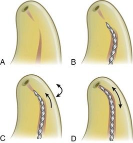
FIGURE 10-5 A, Diagram showing dentinal chips and tissue debris packed in the apical portion of the canal. B, A stiff file is curved in the apical 1 to 3 mm at a 30- to 45-degree bend and placed to the level of the blockage. C, The file is rotated slowly until it catches in the debris then advanced slowly in millimeter strokes to remove the blocking debris. D, Once the catch is felt, the file is carefully rotated in a stem-winding fashion along with a slight in-and-out motion until the tip of the instrument bypasses the obstruction and negotiates the canal to length.
Once the instrument begins to advance further into the canal, or if it expediently reaches the estimated working length, a radiograph is obtained to verify the position of the file. The instrument should not be removed until it can be used in small-amplitude strokes, moving circumferentially to dislodge the packed debris. When sufficient space has been developed through or along the side of the blockage, a smaller-sized Hedström file can be placed to length. Moving this instrument on the outstroke will eliminate the debris. To bore through dense blockage with dentinal chips, chelating agents such as RC-Prep, REDTAC, or liquid ethylenediamine tetraacetic acid (EDTA; see
Whenever there is failure to penetrate or bypass blockage, complete enlarging and shaping at a new working length coronal to the blockage (
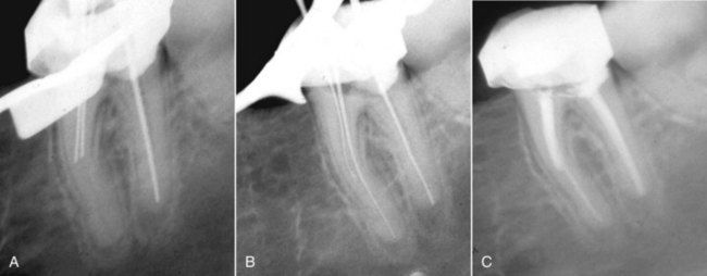
FIGURE 10-6 A, Note the block (most likely a ledge) in the mesial canals of a mandibular molar. B, After placement of a 45-degree bend, one of the canals was penetrated and negotiated to the working length. The other canal could not be penetrated, or possibly it joined the patent canal. C, Obturation with a softened gutta-percha and sealer technique.
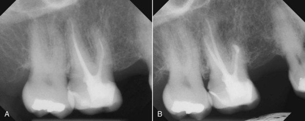
FIGURE 10-7 A, Maxillary molar with a separated instrument segment around the curve in the mesial buccal canal. The tooth was symptomatic. B, Following apical surgery and a root-end filling in the mesial buccal canal; 3-month reevaluation.
Many authors and clinicians would also list separation or breakage of intracanal instruments, especially in curved canals, as a major cause of canal blockage or loss of working length (
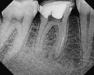
FIGURE 10-8 Broken instrument segment around the curve at the junction of the mesial buccal and distal canals—a common canal blockage.
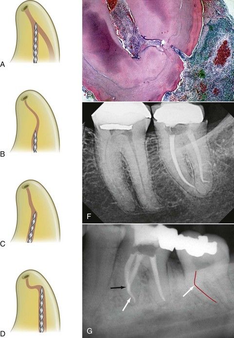
FIGURE 10-9 Diagrammatic representations of the four most common reasons for breakage of any endodontic intracanal instrument: canal convergence (A), S-shaped canals with multiple curves (B), abrupt canal deviations (C), and severe and rapid apical curvatures (D). These anatomic complexities are especially important in the application of NiTi rotary instruments. E, Histologic evidence for t/>
Stay updated, free dental videos. Join our Telegram channel

VIDEdental - Online dental courses


